


GRD-850-UC
Table of contents
 Loading...
SERVICE MANUAL
COPYRIGHT© 2008 Victor Company of Japan, Limited
No.YF228<Rev.001>
2008/2
DIGITAL VIDEO CAMERA
YF228<Rev.001>20082SERVICE MANUAL
GR-D850UC, GR-D850US,
GR-D870UC, GR-D870US,
GR-D875US
COPYRIGHT© 2008 Victor Company of Japan, Limited
Lead free solder used in the board (material : Sn-Ag-Cu, melting point : 219 Centigrade)
TABLE OF CONTENTS
1 PRECAUTIONS . . . . . . . . . . . . . . . . . . . . . . . . . . . . . . . . . . . . . . . . . . . . . . . . . . . . . . . . . . . . . . . . . . . . . . . 1-3
2 SPECIFIC SERVICE INSTRUCTIONS . . . . . . . . . . . . . . . . . . . . . . . . . . . . . . . . . . . . . . . . . . . . . . . . . . . . . . 1-5
3 DISASSEMBLY . . . . . . . . . . . . . . . . . . . . . . . . . . . . . . . . . . . . . . . . . . . . . . . . . . . . . . . . . . . . . . . . . . . . . . . 1-6
4 ADJUSTMENT . . . . . . . . . . . . . . . . . . . . . . . . . . . . . . . . . . . . . . . . . . . . . . . . . . . . . . . . . . . . . . . . . . . . . . . 1-33
5 TROUBLE SHOOTING. . . . . . . . . . . . . . . . . . . . . . . . . . . . . . . . . . . . . . . . . . . . . . . . . . . . . . . . . . . . . . . . . 1-36
GR-D870UCM,GR-D870USM
GR-D875USM [M8D525]
GR-D850UCM,GR-D850USM [M8D523]
1-2 (No.YF228<Rev.001>)
SPECIFICATION
Camcorder
AC Adapter
Specifications shown are for SP mode unless otherwise indicated. E & O.E. Design and specifications subject to change without
notice.
For General Power supply DC 11 V (Using AC Adapter)
DC 7.2 V (Using battery pack)
Power consumption Approx. 2.4 W (2.6 W*) (LCD monitor off, viewfinder on)
Approx. 7.5 W (Maximum; when charging the battery pack)
* Using LED Light
** The LCD Backlight is set to [STANDARD] mode.
Dimensions (W × H × D) 68 mm × 74 mm × 118 mm(2.68" × 2.91" × 4.65")
Weight Approx. 420 g (0.93 lbs) (without battery, cassette and lens cap)
GR-D850 Approx. 485 g (1.07lbs) (incl. battery, cassette and lens cap)
GR-D870 Approx. 490 g (1.08lbs) (incl. battery, cassette and lens cap)
Operating temperature 0°C to 40°C (32°F to 104°F)
Operating humidity 35% to 80%
Storage temperature -20°C to 50°C (-4°F to 122°F)
Pickup 1/6" CCD
Lens F1.8 to 4.0, f=2.2 mm to 77 mm, 35:1 power zoom lens
Filter diameter Ø30.5 mm
LCD monitor 2.7" diagonally measured, LCD panel/TFT active matrix system
Viewfinder Electronic viewfinder with 0.16" color LCD
Speaker Monaural
LED Light Effective distance: 1.5 m (5 ft)
For Digital Video
Camera
Format DV format (SD mode)
Signal format NTSC standard
Recording/Playback
format
Video Digital component recording
Audio PCM digital recording, 32 kHz 4-channel (12-BIT), 48 kHz 2-channel (16-BIT)
Cassette Mini DV cassette
Tape speed SP: 18.8 mm/s, LP: 12.5 mm/s
Maximum recording time
(using 80 min. cassette)
SP: 80 min., LP: 120 min.
For Digital Still
Camera
* GR-D870only
Storage media SD Memory Card/MultiMediaCard
Compression system JPEG (compatible)
File size Still image : 640 × 480 pixels
Picture quality 2 modes (FINE/STANDARD)
For Connectors AV Video output 1.0 V (p-p), 75Ω, analog
Audio output 300 mV (rms), 1 kΩ, analog, stereo
DV Input/output 4-pin, IEEE 1394 compliant
USB Mini USB-B type, USB 1.1 compliant
Power requirement AC 110 V to 240 V, 50 Hz/60 Hz
Output DC 11 V, 1 A
(No.YF228<Rev.001>)1-3
SECTION 1
PRECAUTIONS
1.1 SAFTY PRECAUTIONS
Prior to shipment from the factory, JVC products are strictly
inspected to conform with the recognized product safety and
electrical codes of the countries in which they are to be
sold.However,in order to maintain such compliance, it is equally
important to implement the following precautions when a set is
being serviced.
1.1.1 Precautions during Servicing
(1) Locations requiring special caution are denoted by labels
and inscriptions on the cabinet, chassis and certain parts of
the product.When performing service, be sure to read and
comply with these and other cautionary notices appearing
in the operation and service manuals.
(2) Parts identified by the symbol and shaded ( ) parts
are critical for safety.
Replace only with specified part numbers.
NOTE :
Parts in this category also include those specified to
comply with X-ray emission standards for products
using cathode ray tubes and those specified for
compliance with various regulations regarding
spurious radiation emission.
(3) Fuse replacement caution notice.
Caution for continued protection against fire hazard.
Replace only with same type and rated fuse(s) as
specified.
(4) Use specified internal wiring. Note especially:
• Wires covered with PVC tubing
• Double insulated wires
• High voltage leads
(5) Use specified insulating materials for hazardous live parts.
Note especially:
• Insulation Tape
• PVC tubing
•Spacers
• Insulation sheets for transistors
•Barrier
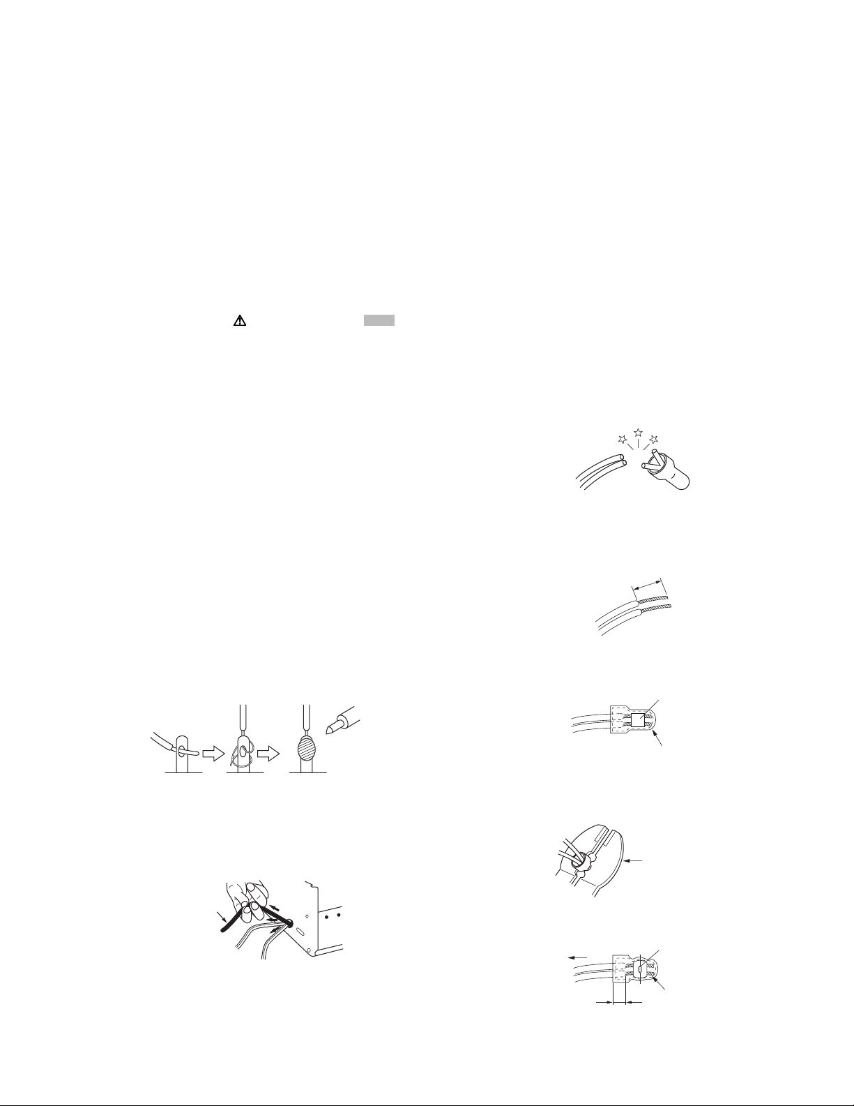
(6) When replacing AC primary side components (transformers,
power cords, noise blocking capacitors, etc.) wrap ends of
wires securely about the terminals before soldering.
Fig.1-1-1
(7) Observe that wires do not contact heat producing parts
(heatsinks, oxide metal film resistors, fusible resistors, etc.)
(8) Check that replaced wires do not contact sharp edged or
pointed parts.
(9) When a power cord has been replaced, check that 10-15
kg of force in any direction will not loosen it.
Fig.1-1-2
(10) Also check areas surrounding repaired locations.
(11) Products using cathode ray tubes (CRTs)In regard to such
products, the cathode ray tubes themselves, the high
voltage circuits, and related circuits are specified for
compliance with recognized codes pertaining to X-ray
emission. Consequently, when servicing these products,
replace the cathode ray tubes and other parts with only the
specified parts. Under no circumstances attempt to modify
these circuits.Unauthorized modification can increase the
high voltage value and cause X-ray emission from the
cathode ray tube.
(12) Crimp type wire connectorIn such cases as when replacing
the power transformer in sets where the connections
between the power cord and power trans former primary
lead wires are performed using crimp type connectors, if
replacing the connectors is unavoidable, in order to prevent
safety hazards, perform carefully and precisely according
to the following steps.
• Connector part number :E03830-001
• Required tool : Connector crimping tool of the proper
type which will not damage insulated parts.
• Replacement procedure
a) Remove the old connector by cutting the wires at a
point close to the connector.Important : Do not
reuse a connector (discard it).
Fig.1-1-3
b) Strip about 15 mm of the insulation from the ends
of the wires. If the wires are stranded, twist the
strands to avoid frayed conductors.
Fig.1-1-4
c) Align the lengths of the wires to be connected.
Insert the wires fully into the connector.
Fig.1-1-5
d) As shown in Fig.1-1-6, use the crimping tool to crimp
the metal sleeve at the center position. Be sure to
crimp fully to the complete closure of the tool.
Fig.1-1-6
e) Check the four points noted in Fig.1-1-7.
Fig.1-1-7
Power cord
cut close to connector
15 mm
Connector
Metal sleeve
1.2
5
2.0
5.5
Crimping tool
Not easily pulled free
Crimped at approx. cente
r
of metal sleeve
Conductors extended
Wire insulation recessed
more than 4 mm
1-4 (No.YF228<Rev.001>)
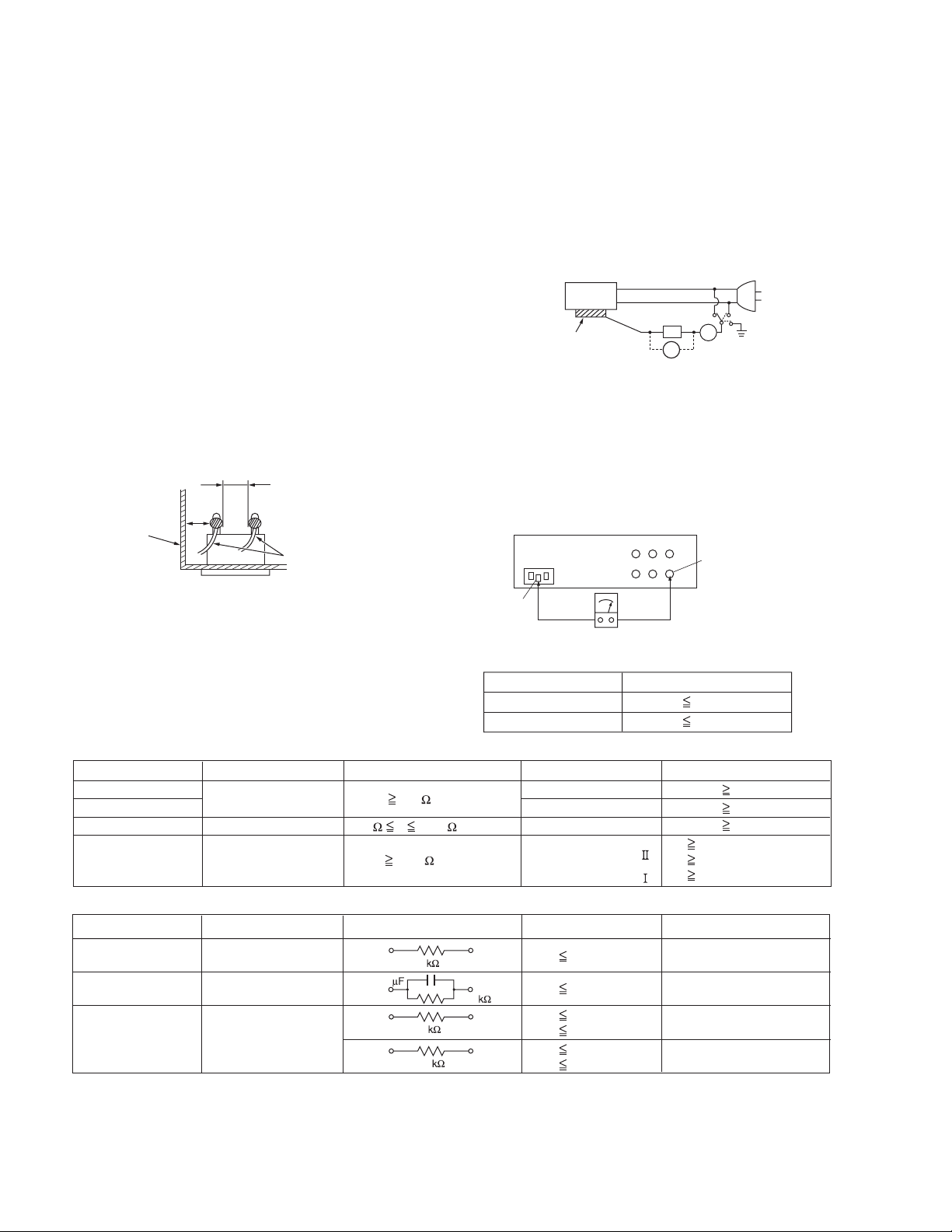
1.1.2 Safety Check after Servicing
Examine the area surrounding the repaired location for damage
or deterioration. Observe that screws, parts and wires have been
returned to original positions, Afterwards, perform the following
tests and confirm the specified values in order to verify
compliance with safety standards.
(1) Insulation resistance test
Confirm the specified insulation resistance or greater
between power cord plug prongs and externally exposed
parts of the set (RF terminals, antenna terminals, video and
audio input and output terminals, microphone jacks,
earphone jacks, etc.).See table 1 below.
(2) Dielectric strength test
Confirm specified dielectric strength or greater between
power cord plug prongs and exposed accessible parts of
the set (RF terminals, antenna terminals, video and audio
input and output terminals, microphone jacks, earphone
jacks, etc.). See Fig.1-1-11 below.
(3) Clearance distance
When replacing primary circuit components, confirm
specified clearance distance (d), (d') between soldered
terminals, and between terminals and surrounding metallic
parts. See Fig.1-1-11 below.
Fig.1-1-8
(4) Leakage current test
Confirm specified or lower leakage current between earth
ground/power cord plug prongs and externally exposed
accessible parts (RF terminals, antenna terminals, video
and audio input and output terminals, microphone jacks,
earphone jacks, etc.).
Measuring Method : (Power ON)Insert load Z between
earth ground/power cord plug prongs and externally
exposed accessible parts. Use an AC voltmeter to
measure across both terminals of load Z. See Fig.1-1-9
and following Fig.1-1-12.
Fig.1-1-9
(5) Grounding (Class 1 model only)
Confirm specified or lower grounding impedance between
earth pin in AC inlet and externally exposed accessible
parts (Video in, Video out, Audio in, Audio out or Fixing
screw etc.).Measuring Method:
Connect milli ohm meter between earth pin in AC inlet and
exposed accessible parts. See Fig.1-1-10 and grounding
specifications.
Fig.1-1-10
Fig.1-1-11
Fig.1-1-12
NOTE :
These tables are unofficial and for reference only. Be sure to confirm the precise values for your particular country and locality.
Chassis
Power cord
primary wire
d'
d
ab
c
V
A
Externally
exposed
accessible part
Z
Exposed accessible part
Grounding Specifications
AC inlet
Region
USA & Canada
Europe & Australia
Grounding Impedance
(
Z
)
Z 0.1 ohm
Z 0.5 ohm
Earth pin
MIlli ohm meter
AC Line Voltage
Region
Japan
Europe & Australia
R 1 M /500 V DC
USA & Canada
1 M R 12 M /500 V DC
R 10 M /500 V DC
Insulation Resistance
(
R
)
Dielectric Strength
Clearance Distance
(
d
)
,
(
d'
)
100 V
100 to 240 V
110 to 130 V
110 to 130 V
200 to 240 V
AC 1 kV 1 minute
AC 1.5 kV 1 minute
AC 1 kV 1 minute
(
Class
)
(
Class
)
AC 3 kV 1 minute
AC 1.5 kV 1 minute
d, d' 3 mm
d, d' 4 mm
d, d' 3.2 mm
d' 8 m m
(
Power cord
)
d' 6 m m
(
Primary wire
)
d 4 m m
AC Line Voltage
Region
Japan
Europe & Australia
USA & Canada
Load Z
Leakage Current (i)
a, b, c
100 V
110 to 130 V
110 to 130 V
220 to 240 V
i 1 mA rms
i 0.5 mA rms
i 0.7 mA peak
i 2 mA dc
i 0.7 mA peak
i 2 mA dc
Exposed accessible parts
Exposed accessible parts
Antenna earth terminals
Other terminals
1
1.5
2
50
0.15
(No.YF228<Rev.001>)1-5
SECTION 2
SPECIFIC SERVICE INSTRUCTIONS
2.1 DIFFERENCE LIST
The following table indicate main different points between models GR-D850UC, GR-D850US, GR-D870UC, GR-D870US,
and GR-D875US.
MODEL NAME GR-D850UC GR-D850US GR-D870UC
DSC
NO NO YES
CD-ROM NO NO YES
USB CABLE/TERMINAL NO NO YES
REMOTE CONTROL UNIT NO NO NO
MODEL NAME GR-D870US GR-D875US
DSC
YES YES
CD-ROM YES YES
USB CABLE/TERMINAL YES YES
REMOTE CONTROL UNIT NO YES(RM-V740US)
1-6 (No.YF228<Rev.001>)
SECTION 3
DISASSEMBLY
3.1 BEFORE ASSEMBLY AND DISASSEMBLY
3.1.1 Precautions
• Be sure to disconnect the power supply unit prior to mounting
and soldering of parts.
• Prior to removing a component part that needs to disconnect
its connector(s) and its screw(s), first disconnect the wire(s)
from the connector(s), and then remove the screw(s).
• When connecting/disconnecting wires, pay enough attention
not to damage the connectors.
• When inserting the flat wire to the connector, pay attention to
the direction of the flat wire.
• Be careful in removing the parts to which some spacer or
shield is attached for reinforcement or insulation.
• When replacing chip parts (especially IC parts), first remove
the solder completely to prevent peeling of the pattern.
• Tighten screws properly during the procedures. Unless
otherwise specified, tighten screws at a torque of 0.088N
·m
(0.9kgf
·cm). However, as this is a required value at the time of
production, use the value as a measuring stick when
proceeding repair services. (See "SERVICE NOTE(1)" as for
tightening torque.)
3.1.2 Destination of connectors
3.1.3 Disconnection of connectors (Wires)
Fig.3-1-1
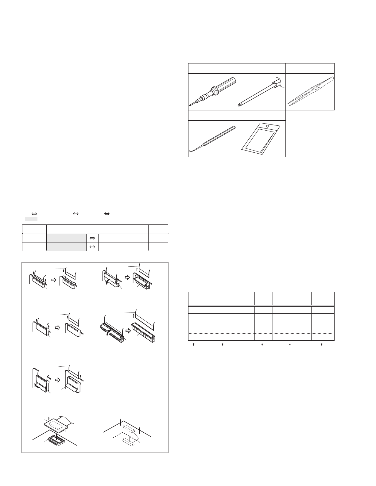
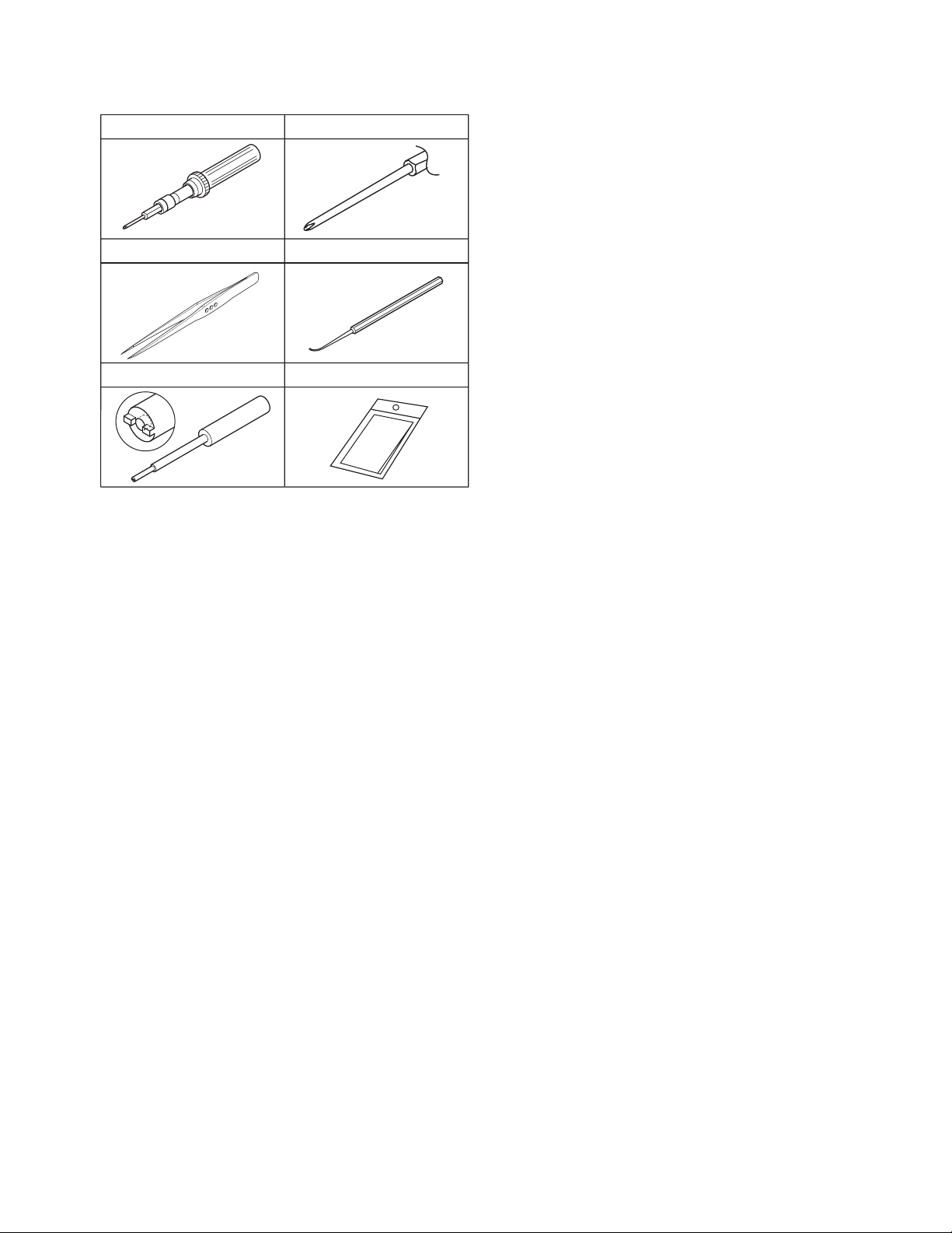
3.1.4 Tools required for disassembly and assembly
Fig.3-1-2
• Torque driver
Be sure to use to fastening the mechanism and exterior parts be-
cause those parts must strictly be controlled for tightening torque.
• Bit
This bit is slightly longer than those set in conventional torque
drivers.
• Tweezers
To be used for removing and installing parts and wires.
• Chip IC replacement jig
To be used for replacement of IC.
• Cleaning cloth
Recommended cleaning cloth to wipe down the video heads,
mechanism (tape transport system), optical lens surface.
3.2 ASSEMBLY AND DISASSEMBLY OF MAIN PARTS
3.2.1 Assembly and disassembly
When reassembling, perform the step(s) in reverse order.
(∗1) Order of steps in Procedure
When reassembling, preform the step(s) in the reverseorder.
These numbers are also used as the identification (location)
No. of parts Figures.
(∗2) Part to be removed or installed.
(∗3) Fig. No. showing Procedure or Part Location.
(∗4) Identification of part to be removed, unhooked, unlocked,
released, unplugged, unclamped or unsoldered.
S = Screw L = Lock, Release, Hook
SD = Solder CN = Connector
[Example]
• 4 (S1a) = Remove 4 S1a screws.
• 3 (L1a) = Disengage 3 L1a hooks.
• 2 (SD1a) = Unsolder 2 SD1a points.
• CN1a = Remove a CN1a connector.
(∗5) Adjustment information for installation.
CN2a
CN2b
MAIN CN101
MAIN CN103
40
10
CONN. No. PIN No.CONNECTOR
Two kinds of double-arrows in connection tables respectively
show kinds of connector/wires.
: The connector of the side to remove
: Wire: Flat wire : Board to board (B-B)
MONI BW CN761
MINI BW CN762
B-B Connector
B-B Connector
B-B Connector
· Pull the both ends of the board in the direction of the arrow, and remove the B-B Connector.
· Pull the both ends of the board in the direction
of the arrow, and remove the B-B Connector.
FPC Connector
Wire
· Pull both ends of the connector in the arrow
direction, remove the lock and disconnect the flat
wire.
FPC Connector
Lock
Wire
· Extend the locks in the direction of the arrow for
unlocking and then pull out the wire. After
removing the wire, immediately restore the locks
to their original positions because the locks are
apt to come off the connector.
· Extend the locks in the direction of the arrow for
unlocking and then pull out the wire. After
removing the wire, immediately restore the locks
to their original positions because the locks are
apt to come off the connector.
· Extend the locks in the direction of the arrow for
unlocking and then pull out the wire. After
removing the wire, immediately restore the locks
to their original positions because the locks are
apt to come off the connector.
FPC Connector
Wire
FPC Connector
Lock
Wire
FPC Connector
Wire
Lock
Lock
Cleaning cloth
KSMM-01
Torque driver
YTU94088
Bit
YTU94088-003
Chip IC replacement jig
PTS40844-2
Tweezers
P-895
( 4) ( 5)( 2) ( 3)( 1)
TOP COVER ASSY
UPPER ASSY
(Inc. VF ASSY,
SPEAKER/MONITOR)
E.VF UNIT(B/W)
C1
C2-1
C2-2
4(S1a), 3(L1a),CN1a
(S2a),2(S2b),3(S2c)
2(SD1a),
L2,CN2a,b
2(S8),L8,CN8a
-
-
NOTE 8
[1]
[2]
[8]
STEP
No.
PART
NOTE
Fig.
No.
POINT
(No.YF228<Rev.001>)1-7
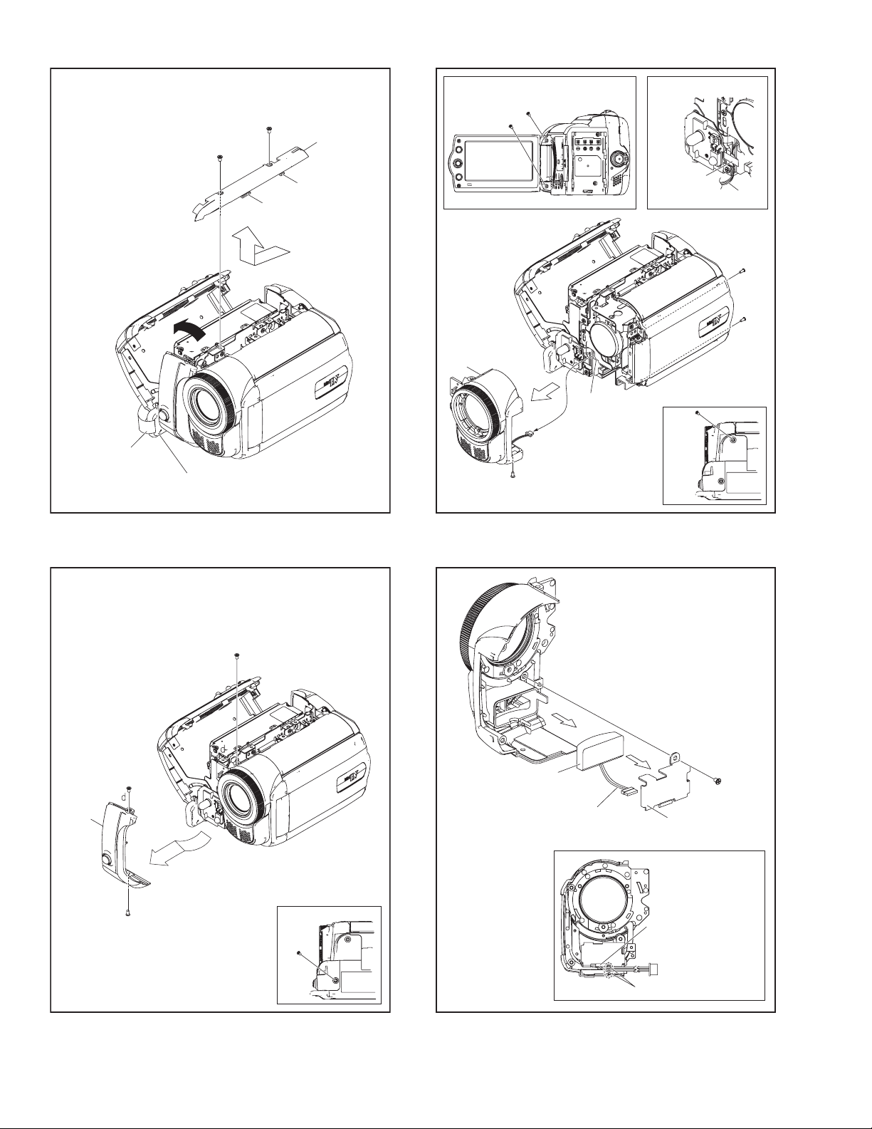
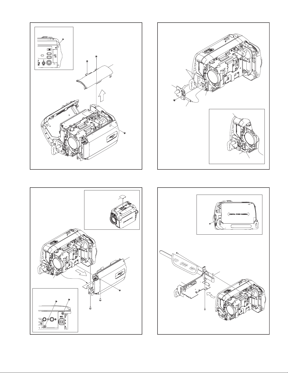
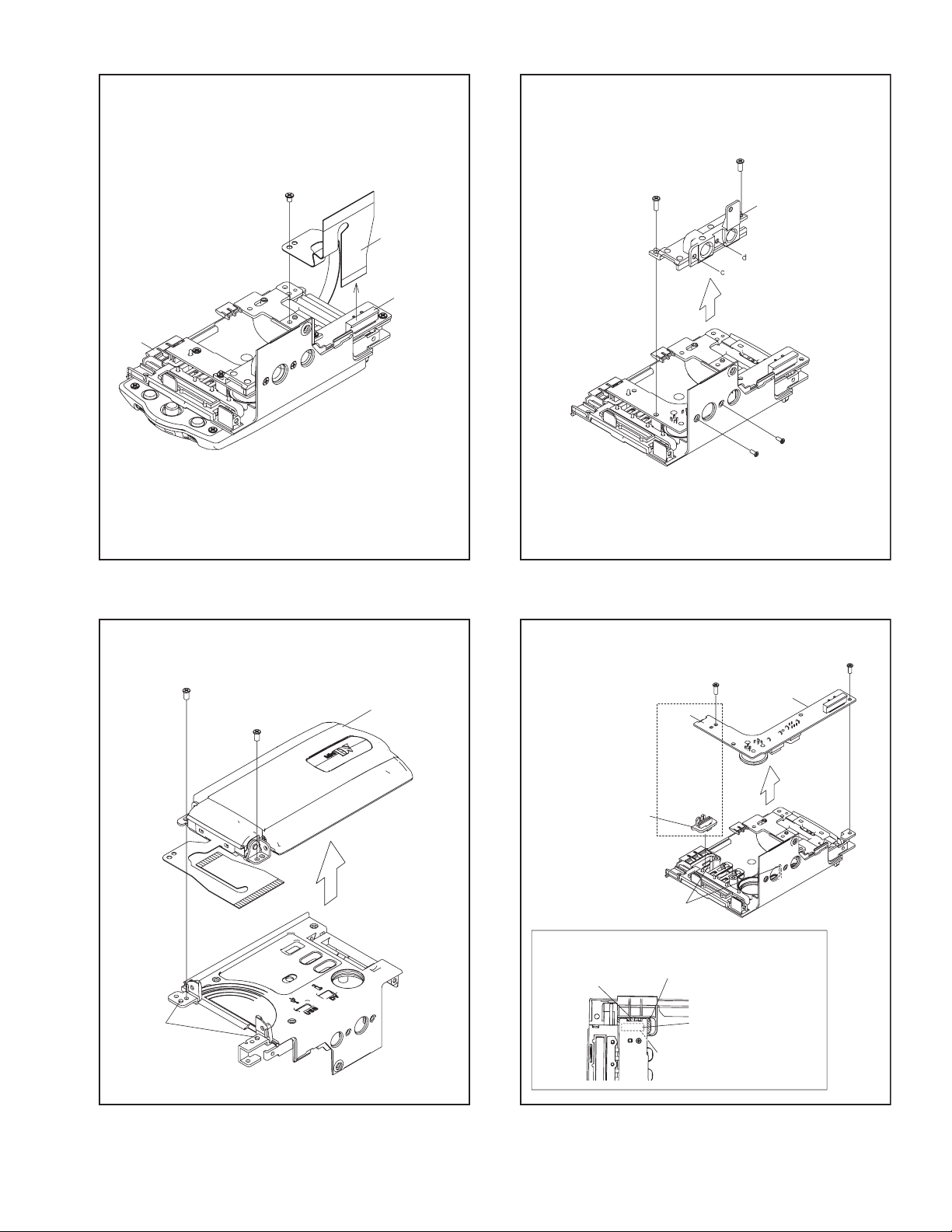
3.2.2 Assembly/Dissambly of cabinet parts and electrical parts
zDisassembly procedure
NOTE1:
Pull out the GRIP BELT from the HOOK first as it interferes
with the procedure.
NOTE3:
When attaching, be careful with the wiring.
After connecting the wire to the connector, locate the wire
behind the FPC.
NOTE4:
When attaching, be careful with the wiring (MIC).
NOTE6a:
When removing, remove the COVER (JIG) first.
NOTE6b:
Please refer to Fig.3-2-18A and the following procedure for
removing the UPPER ASSY.
NOET7:
When attaching, be careful with the wiring.
NOTE8a:
During the procedure, be careful in handling the parts.
When the LOWER CASE ASSY is removed, the SHAFT
may come off.
NOTE8b:
When attaching, be careful with the FPC.
NOET10a:
During the procedure, be careful in handling the parts.
Be careful in handling the FPC as the switch connected to the
FPC is screwed on the back of the CASSETTE COVER (TOP).
NOET10b:
Be careful not to lose the KNOB (EJECT), or remove the
KNOB (EJECT) during the following procedures as it is easily
comes off when the CASSETTE COVER (TOP) is removed.
NOET10c:
When removing, carefully peel off and release the FPC as it
sticks to the ARM ASSY.
NOTE11a:
When attaching, be careful with the FPC.
NOTE11b:
When attaching, close the ARM ASSY.
When attaching, be careful with the wiring.
NOTE12:
When attaching, be careful with the wiring.
NOTE13a:
When removing, remove the screw (No.27) located under
the COVER (JACK) first.
NOTE13b:
When removing, be careful not to damage the HOOK (L13b).
NOTE14a:
When removing, the brackets are attached to the OP
BLOCK ASSY. During the procedure, remove the brackets
if necessary.
NOTE14b:
Refer to 3.2.3 Assembly/Disambly of [14] OP BLOCK ASSY/
CCD BOARD ASSYof OP BLOCK ASSY.
NOTE15a:
When removing, remove the 4 screws (No.31-34), and then
release the HOOK.
NOTE15b:
During the procedure, be careful with the grease applied to
the both sides.
NOTE16:
When attaching, be careful with the FPC.
NOTE18a:
Pay special attention in handling the removed UPPER
ASSY as the FPC is unstable.
NOTE18b:
Refer to 3.2.4 Disassembly of [18] MONITOR ASSY of
MONITOR ASSY.
NOTE20a:
When removing, be careful in handling the KNOB (SLIDE)
as they may come off.
NOTE20b:
When attaching, make sure that the LEVER of the SW inter-
locks with the KNOB (SLIDE).
zDestination of connectors
COVER(LAST)
LOWER CASE(FRO) ASSY
FRONT CAVER ASSY
MIC
TOP COVER ASSY
UPPER ASSY
FRONT BOARD ASSY
LOWER CASE ASSY
CASSETTE COVER(SIDE)
CASSETTE COVER(TOP)
REAR ASSY
REAR BOARD ASSY
LOWER CASE(P) ASSY
OP BLOCK ASSY
ARM ASSY
MAIN BOARD ASSY
MECHANISM ASSY
MONITOR ASSY
TRIPOD(BASE)
JACK BOARD ASSY
STEP
No.
PART NAME
Fig.
No.
POINT NOTE
[1]
[2]
[3]
[4]
[5]
[6]
[7]
[8]
[9]
[10]
[11]
[12]
[13]
[14]
[15]
[16]
[17]
[18]
[19]
[20]
GRIP BELT,2(S1),L1a,b
3(S2)
2(S3a),S3b,CN3
S4
S5a,2(S5b)
COVER(JIG),S6a,b,c,CN6
S7,2(L7),CN7
S8a,b
-
2(S9),6(L9)
2(S10a)
S10b
2(S11),L11a,b,CN11a,b
S12,CN12
S13,L13a,b
CN14a,3(S14),L14,CN14b
4(S15),L15
CN16a,b,c,d,e,L16a,b
4(S17)
S18a,CN18
2(S18b),2(L18)
S19a,3(S19b)
S20a,b,2(L20)
3-2-1
3-2-2
3-2-3
3-2-4
3-2-5
3-2-6
3-2-7
3-2-8A
3-2-8B
3-2-9
3-2-10A
3-2-10B
3-2-11
3-2-12
3-2-13
3-2-14
3-2-15
3-2-16A
3-2-17
3-2-18A
3-2-18B
3-2-19
3-2-20
NOTE1
-
NOTE3
NOTE4
-
NOTE6a,b
NOTE7
NOTE8a
NOTE8b
-
NOTE10a
NOTE10b,c
NOTE11a,b
NOTE12
NOTE13a,b
NOTE14a,b
NOTE15a,b
NOTE16
-
NOTE18a
NOTE18b
-
NOTE20a,b
CN3 MAIN CN2601 MIC - 4
CN6 MAIN CN103
JACK/MONITOR
CN401/CN7002 50/24,28
CN7 MAIN CN108 FRONT CN801 8
CN11a MAIN CN101/CN106
REAR
CN501/CN504 40/32
CN11b MAIN CN105
POWER/ZOOM UNIT
- 12
CN14a MAIN CN4201 CCD CN5001 20
CN14b MAIN CN4901 OP BLOCK ASSY
- 25
CN16a MAIN CN1604 SENSOR - 16
CN16b MAIN CN1603 CAPSTAN MOTOR
- 18
CN16c MAIN CN1602 DRUM MOTOR - 11
CN16d MAIN CN3501 HEAD - 8
CN16e MAIN CN1601
LOADING MOTOR
-
8
/ROTARY ENCODER
CN18 JACK CN401 MONITOR CN7002 24
CN.
No.
PIN
No.
CONNECTOR
1-8 (No.YF228<Rev.001>)
Fig.3-2-1
Fig.3-2-2
Fig.3-2-3
Fig.3-2-4
2
(S1)
GRIP BELT
HOOK
NOTE1
[1]
L1b
L1a
1
(S1)
[2]
5
(S2)
3
(S2)
4
(S2)
3
(S2)
FPC
WIRE
[3]
6
(S3a)
6
(S3a)
CN3
NOTE3
NOTE3
8
(S3b)
8
(S3b)
7
(S3a)
7
(S3a)
[4]
these bosses.
Slot WIRE(MIC) between
NOTE4
NOTE4
9
(S4)
PLATE(MIC)
WIRE(MIC)
BOSS
(No.YF228<Rev.001>)1-9
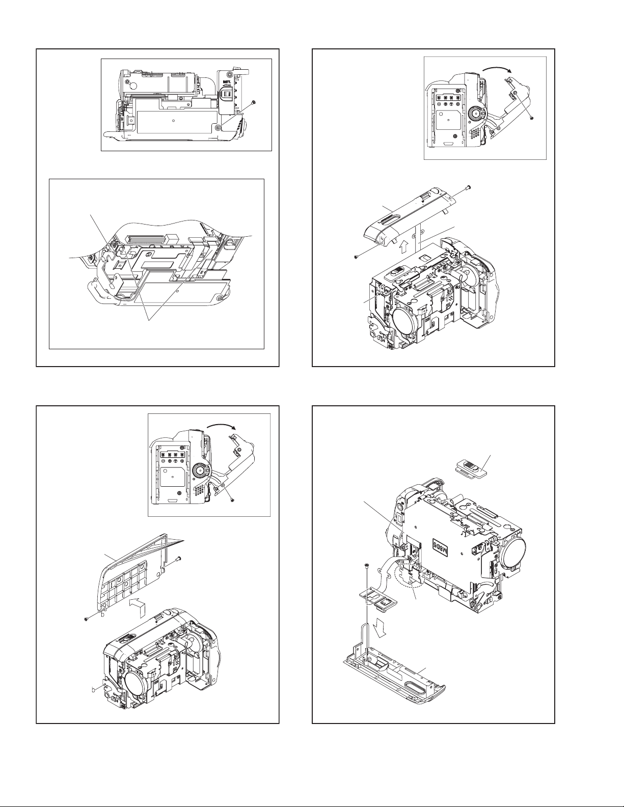
Fig.3-2-5
Fig.3-2-6
Fig.3-2-7
Fig.3-2-8A
[5]
10
(S5a)
12
(S5b)
10
(S5a)
11
(S5b)
CN6
COVER(JIG)
[6]
14
(S6b)
13
(S6a)
NOTE6b
15
(S6c)
13
(S6a)
14
(S6b)
NOTE6a
[7]
16
(S7)
NOTE7
NOTE7
CN7
Dress FPC as shown in figure.
L7
FPC
FPC
[8]
SHAFT
NOTE8a
18
(S8b)
17
(S8a)
17
(S8a)
1-10 (No.YF228<Rev.001>)
Fig.3-2-8B
Fig.3-2-9
Fig.3-2-10A
Fig.3-2-10B
Ensure this part of LOWER CASE is on top of FRAME ASSY.
Fold the MECHA FPC towards LOWER SIDE
when attaching LOWER CASE ASSY.
NOTE8b
18
(S8b)
[9]
20
(S9)
L9
19
(S9)
19
(S9)
22
(S10a)
21
(S10a)
FPC
c
c
[10]
NOTE10a
21
(S10a)
[10]
23
(S10b)
ARM ASSY
FPC
NOTE10c
KNOB(EJECT)
NOTE10b
(No.YF228<Rev.001>)1-11
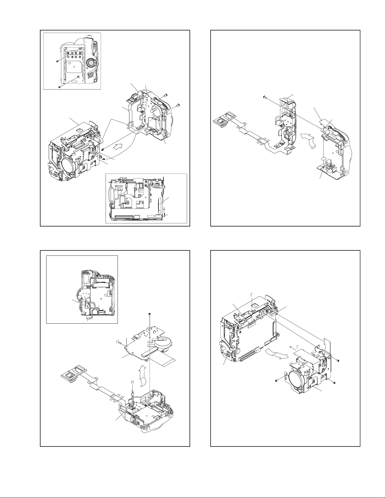
Fig.3-2-11
Fig.3-2-12
Fig.3-2-13
Fig.3-2-14
[11]
CN11a
CN11b
ARM ASSY
NOTE11a
NOTE11b
SW(EJECT)
FPC
24
(S11)
25
(S11)
24
(S11)
25
(S11)
L11a
CN11a
CN11b
L11b
[12]
26
(S12)
WIRE
BOSS
CN12
NOTE12
NOTE12
L13a
L13b
ASSY
REAR COVER
27
(S13)
[13]
NOTE13a
NOTE13b
L14
CN14b
CN14a
29
(S14)
28
(S14)
[14]
NOTE14a,b
30
(S14)
1-12 (No.YF228<Rev.001>)
Fig.3-2-15
Fig.3-2-16A
Fig.3-2-16B
Fig.3-2-17
L15
g
g
31
(S15)
32
(S15)
33
(S15)
33
(S15)
34
(S15)
34
(S15)
[15]
NOTE15b
NOTE15a
HOOK
CN16b
CN16c
CN16d
A
B
C
C
D
E
CN16a
AA
BB
DD
E E
L16a
CN16e
L16b
35
(S16)
[16]
NOTE16
CN16a
CN16b CN16c CN16d CN16e
NOTE16
FRAME ASSY
36
(S17)
37
(S17)
39
(S17)
38
(S17)
[17]
(No.YF228<Rev.001>)1-13
Fig.3-2-18A
Fig.3-2-18B
Fig.3-2-19
Fig.3-2-20
FPC
40
(S18a)
[18]
NOTE18a
CN18
NOTE18b
41
(S18b)
42
(S18b)
L18
[18]
45
(S19b)
46
(S19b)
43
(S19a)
44
(S19b)
[19]
KNOB(SLIDE)
KNOB(SLIDE)
LEVER
JACK
BOARD ASSY
SW
47
(S20a)
48
(S20b)
[20]
L20
SW
NOTE20b
NOTE20a
NOTE20b
1-14 (No.YF228<Rev.001>)
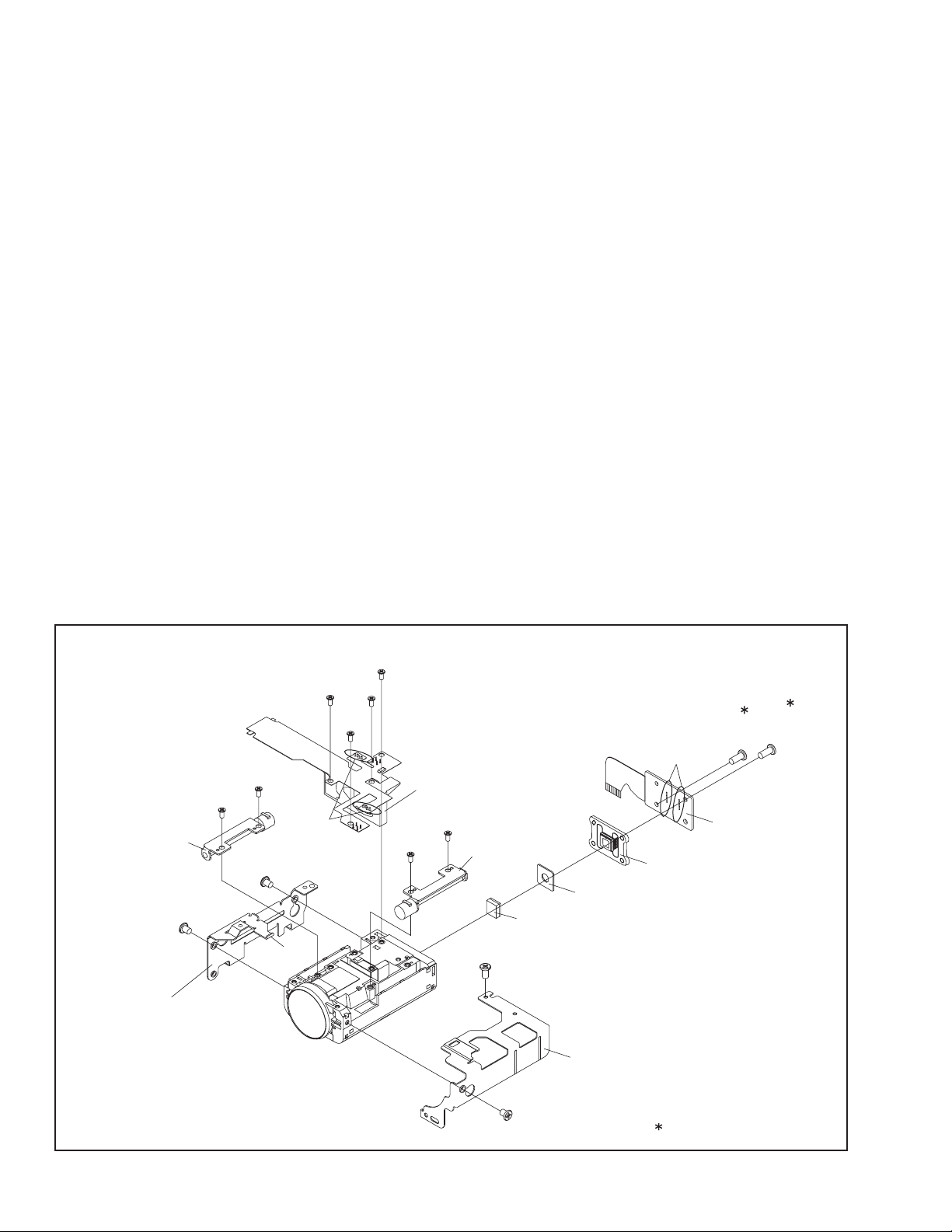
3.2.3 Assembly/Disambly of [14] OP BLOCK ASSY/CCD BOARD ASSY
zPrecautions
(1) Be careful in handling the CCD IMAGE SENSOR, OPTI-
CAL LPF and the LENS components. Pay special atten-
tion not to soil or damage the surfaces., especially with
regard to surface contamination, attached dust or
scratching. If fingerprints are present on the surface they
should be wiped away using either a silicon paper, clean
chamois or the cleaning cloth.
(2) The CCD IMAGE SENSOR may have been shipped with
a protective sheet attached to the transmitting glass.
When replacing the CCD IMAGE SENSOR, do not peel
off this sheet from the new part until immediately before
it is mounted in the OP BLOCK ASSY.
(3) As the CUSHION(OP) protects the OP BLOCK ASSY
from scratches or damages, leave the CUSHION as
long as it does not interfere with the procedure.
zDisassembly of OP BLOCK ASSEMBLY / CCD BOARD AS-
SEMBLY
(1) Unsolder the fourteen soldered points (SD11a) of the
CCD BOARD ASSY.
(2) Remove the two screws (1,2), and then remove the CCD
BOARD ASSY and the CCD BASE ASSY.
NOTE11a:
When removing the CCD BASE ASSY, be careful in
handling as the CCD IMAGE SENSOR may be re-
moved together with the SHEET and the OP LPF at-
tached.
NOTE11\b:
Replace the CCD IMAGE SENSOR as a CCD BASE
ASSY, not as a single part replacement.
zAssembly of OP BLOCK ASSEMBLY / CCD BOARD AS-
SEMBLY
(1) Set the OPTICAL LPF first, and then the SHEET to the
OP BLOCK ASSY.
NOTE11c:
Be careful with the attachment direction of the OP
LPF.
(2) Attach the CCD BASE ASSY first, then the CCD BASE
ASSY so that the SHEET stays in place, and then tighten
with the two screws (1, 2).
(3) Solder the 14 points (SD11a) on the CCD BOARD AS-
SY.
zReplacement of service repair parts
The service repair parts for the OP BLOCK ASSY are as listed
below.
When replacing the parts, remove the BKT OP (1) and (2) first
if necessary.
When replacing parts, be careful not to cut the FPCs or dam-
age any parts by soldering (excessive heat).
(1) FOCUS MOTOR UNIT
(2) ZOOM MOTOR UNIT
(3) AUTO IRIS UNIT
NOTE 13e:
When replacing the FOCUS MOTOR UNIT or the ZOOM
MOTOR UNIT, solder the FPC at a space of about 0.5 mm
above the terminal pin.
NOTE 13f:
The IRIS MOTOR UNIT includes the FPC ASSY and two
sensors.
Fig.3-2-21
NOTE14c
NOTE14a,b
NOTE14d
CCD BOARD
ASSY
CCD BASE ASSY
UNIT
AUTO IRIS
FOCUS MOTOR
UNIT
ZOOM MOTOR
UNIT
HOOK
SHIEET
OP LPF
7
(S14d)
9
(S14d)
10
(S14d)
11
(S14d)
12
(S14d)
13
(S14d)
14
(S14d)
5
(S14c)
6
(S14c)
1
(S14a)
2
(S14a)
8
(S14d)
4
(S14c)
3
(S14c)
SD14a
SD14b
:0.147 N・m (1.5kgf・cm)
BKT OP(2) ASSY
BKT OP(1) ASSY

(No.YF228<Rev.001>)1-15
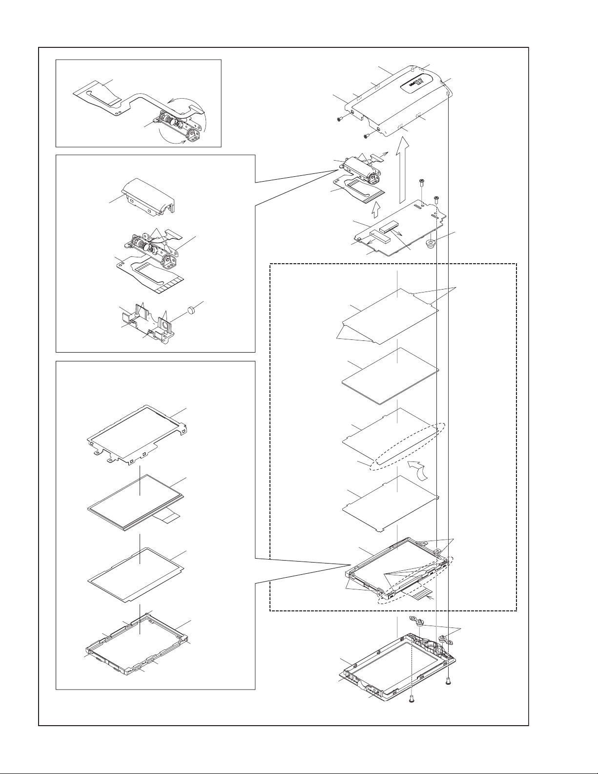
3.2.4 Disassembly of [18] MONITOR ASSY
zCAUTIONS
(1) During the procedure, be careful in handling the LCD
MODULE and other parts. Pay special attention not to
damage or soil the monitor screen.
If fingerprints are left on the screen, wipe them with clean
chamois leather or a cleaning cloth.
zRemoving MONITOR ASSEMBLY
(1) Remove the 2 screws (1 and 2).
(2) Turn the HINGE UNIT ASSY 90º, and remove the two
screws (3 and 4).
(3) Remove the MONITOR COVER ASSY by removing the
6 hooks (L18a-f).
(4) Release the lock of the connector (CN18a), and remove
the HINGE UNIT by lifting it up.
NOTE18a:
During the procedure, be careful in handling the FPC.
(5) Release the lock of the connector (CN18b), and pull out
the FPC.
(6) Remove the 2 screws (5 and 6), and remove the MONI-
TOR BOARD ASSY .
NOTE18b:
Be careful in handling as the parts located below may
be misaligned or removed when the MONITOR
BOARD ASSY is removed.
Attach the MONITOR BOARD ASSY by lifting up the
MONITOR CASE as the KNOB (CURSOR) that is at-
tached to the BOARD sticks out toward the LCD
screen.
NOTE18c:
When replacing the MONITOR CASE or when there is
no need to replace individual parts in the MONITOR
CASE, remove the whole parts from the SHEET
(M.REF) to the LCD SA as a unit.
(7) Remove the SHEET (M.REF), LIGHT GUIDE, SHEET
(M/DIFF), and the SHEET(BEF)1.
NOTE18d:
When attaching, insert one side of the SHEET (M/
DIFF) under the LCD CASE RIB.
NOTE18e:
When attaching, insert each tab on both sides of the
SHEET (M.REF) into the LCD CASE notch.
(8) Remove the SHIELD CASE(MONI), LCD MODULE,
SHEET(COVER) and the LCD CASE.
NOTE18f:
During the procedure, handle the 4 parts (SHIELD
CASE(MONI), LCD MODULE, SHEET(COVER)) to-
gether.
zRemoving HINGE UNIT ASSEMBLY
(1) While removing the 6 HOOKs (L18t-w) from one side
and then from the other side, remove the HINGE COV-
ER (U).
NOTE18g:
Be careful in handling the HINGE ASSY as grease is
applied inside.
(2) Remove the HINGE COVER(L).
(3) Remove the MAGNET.
NOTE18h:
During the procedure, be careful in handling the mag-
net.
When attaching, set the negative pole outside as
shown in the figure. Be careful when removing as
there is no marking.
NOTE18j:
During the procedure, be careful in handling the FPC.
NOTE18k:
The FPC is rolled around the axis of rotation of the
HINGE ASSY 2.5 rounds (2.5times).
The connecting side to the MONITOR BOARD ASSY
is placed inside.
1-16 (No.YF228<Rev.001>)
Fig.3-2-22
FPC
b
MONITOR COVER
ASSY
(M.REF)
SHEET
LIGHT GUIDE
(M/DIFF)
SHEET
(BEF)1
SHEET
MONITOR CASE
(MONI)
BUTTON
H.COVER(U)
HINGE ASSY
FPC
FPC
H.COVER(L)
MAGNET
1
(S18a)
2
(S18a)
3
(S18b)
5
(S18c)
6
(S18c)
L18a
L18b
L18c
L18g
L18h
CN18a
CN18b
L18k
L18j
L18f
L18e
L18d
4
(S18b)
a
b
C
C
B
B
a
L18g
L18v
L18t
L18u
L18w
LCD SA
LIB
LIB
LIB
<HINGE UNIT ASSY>
HINGE UNIT
HINGE UNIT
ASSY
MONITOR
BOARD ASSY
KNOB
(CURSOR)
[18]
NOTE18d
NOTE18d
NOTE18d
NOTE18d
NOTE18e
NOTE18e
NOTE18g
NOTE18a
NOTE18f
NOTE18b
NOTE18e
NOTE18c
NOTE18e
NOTE18k
NOTE18g
NOTE18j
NOTE18h
SHEET(COVER)
LCD CASE
(MONI)
SHILD CASE
LCD MODULE
L18q
L18r
L18s
L18t
L18m
L18n
L18p
<LCD SA>
NOTE18f
(No.YF228<Rev.001>)1-17
3.3 DVC MECHANISM
3.3.1 TOOLS REQUIRED FOR ADJUSTMENTS
1. Torque driver
Be sure to use to fastening the mechanism and exterior parts
because those parts must strictly be controlled for tightening
torque.
Torque setting value of torque driver is limited. At the values
over the maximum torque setting value, fasten a screw manu-
ally not to damage the screw thread.
2. Bit
This bit is slightly longer than those set in conventional torque
drivers.
3. Tweezers
To be used for removing and installing parts and wires.
4. Chip IC replacement jig
To be used for replacement of part.
5.Guide driver
To be used for the height adjustment such as the guide rollers.
6. Cleaning cloth
Recommended cleaning cloth to wipe down the video heads,
mechanism (tape transport system), optical lens surface.
3.3.2 Precautions
(1) When fastening parts, pay careful attention to the tightening torque of each screw. Unless otherwise specified, tighten a screw
with the torque of 0.055 N
·m (0.56 kgf·cm).
(2) Be sure to disconnect the set from the power supply before fastening and soldering parts.
(3) When disconnecting/connecting wires, be careful not to get them and their connectors damaged.
(4) When replacing parts, be very careful neither to damage other parts nor to fit wrong parts by mistake.
Torque driver
YTU94088
1.
Bit
YTU94088-003
2.
3.
Chip IC replacement jig
PTS40844-2
4.
Tweezers
P-895
5.
Guide driver
YTU94148A-1
6.
Cleaning cloth
KSMM-01
1-18 (No.YF228<Rev.001>)
3.3.3 Notes on procedure for disassembly/assembly
The DISASSEMBLY PROCEDURE TABLE shows the procedure to disassemble/reassemble mechanism parts.
Carefully read the following explanation before starting actual disassembling/reassembling work. The item numbers(circled num-
bers)in the following explanation correspond to those appearing under respective columns of the table.
*1 Numbers appearing in this column indicate the order to re-
move parts. When reassembling, follow these numbers in
the reverse order. Circled numbers in this column corre-
spond to those appearing in drawings of this section.
*2 This column shows part names corresponding to numbers
in the left column.
*3 The symbol (T or B)appearing in this column shows the
side which the objective part is mounted on.
T =the upper side, B =the lower side
*4 Symbols appearing in this column indicate drawing num-
bers.
*5 This column indicates parts and points such as screws,
washers,springs,and others to be removed/fitted for disas-
sembling/reassembling the mechanism. Besides such the
parts, this column occasionally indicates working points.
Example
• Remove (W1)=Washer W1.
• Remove the solder at (SD1)=Point SD1.
• Disconnect A = Connector A.
*6 Numbers in this column represent the numbers of notes in
the text.
(For parts that need phase adjustment after reassembling,
refer to “MECHANISM ADJUSTMENTS”.)
*7 This column indicates required after-disassembling/-reas-
sembling work such as phase adjustment or mechanism
adjustment.
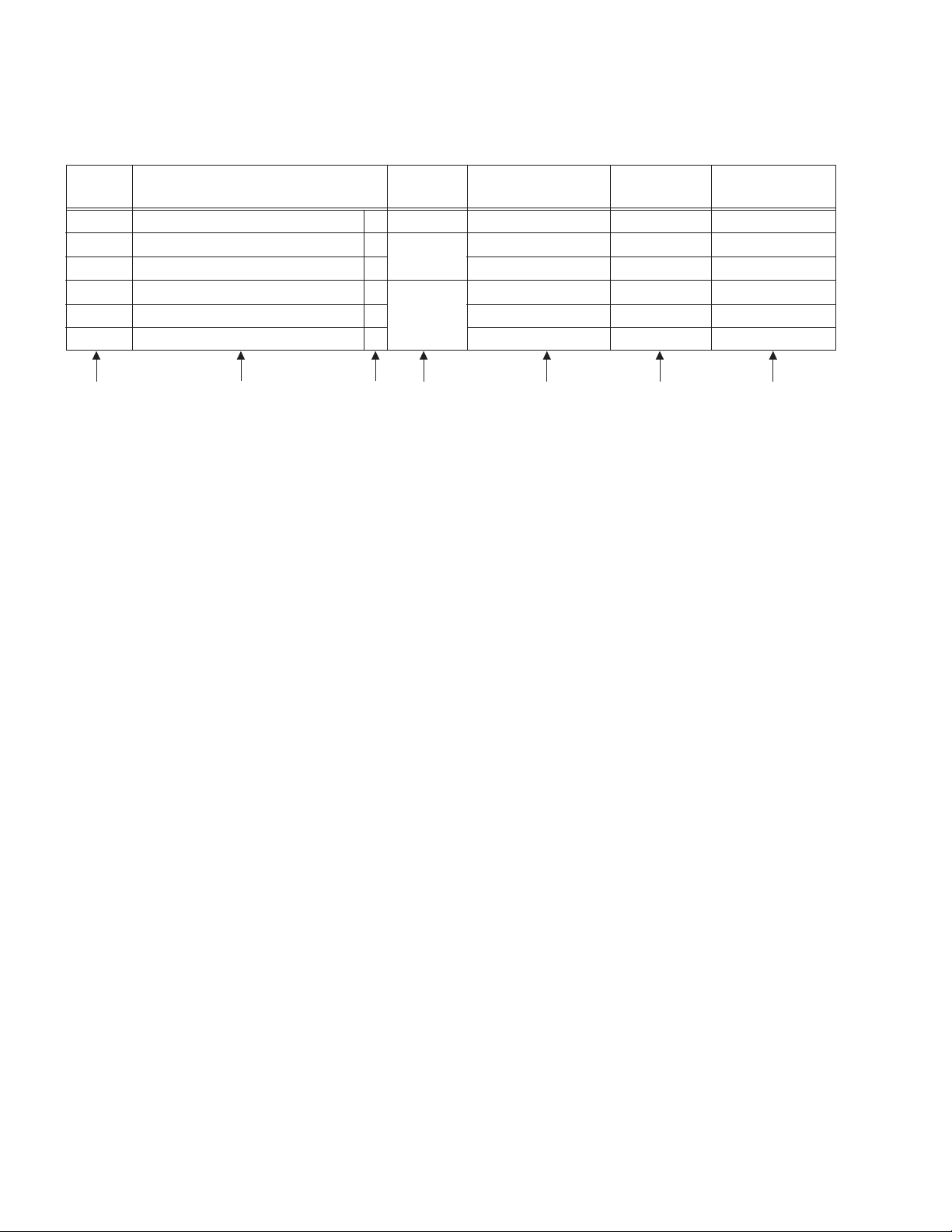
NO. PART NAME FIG. POINT NOTE REMARKS
[1]
[2]
[3]
[4]
[5]
[6]
CASSETTE HOUSING ASSY T Fig.2-4-3 3(S1),(L1a)-(L1e)
NOTE 1 a,b,c,d
ADJUSTMENT
UPPER BASE ASSY T Fig.2-4-4 (S2),(L2a),(L2b)
NOTE 2
DRUM ASSY T (S3a),2(S3b)
NOTE 3 a,b
REEL DISK ASSY(SUP) T Fig.2-4-5 (W4)
(W5a),(W5b),(W5c)
(W6),(S6a),2(S6b)
NOTE 4 a
REEL DISK ASSY(TU) T
NOTE 5 a,b
REEL COVER ASSY T
NOTE 6
ADJUSTMENT
*1 *2 *3 *4 *5 *6 *7
Example
P= Spring
W = Washer
S= Screw
* = Lock (L),soldering (SD),shield,connector (CN),etc.
(No.YF228<Rev.001>)1-19
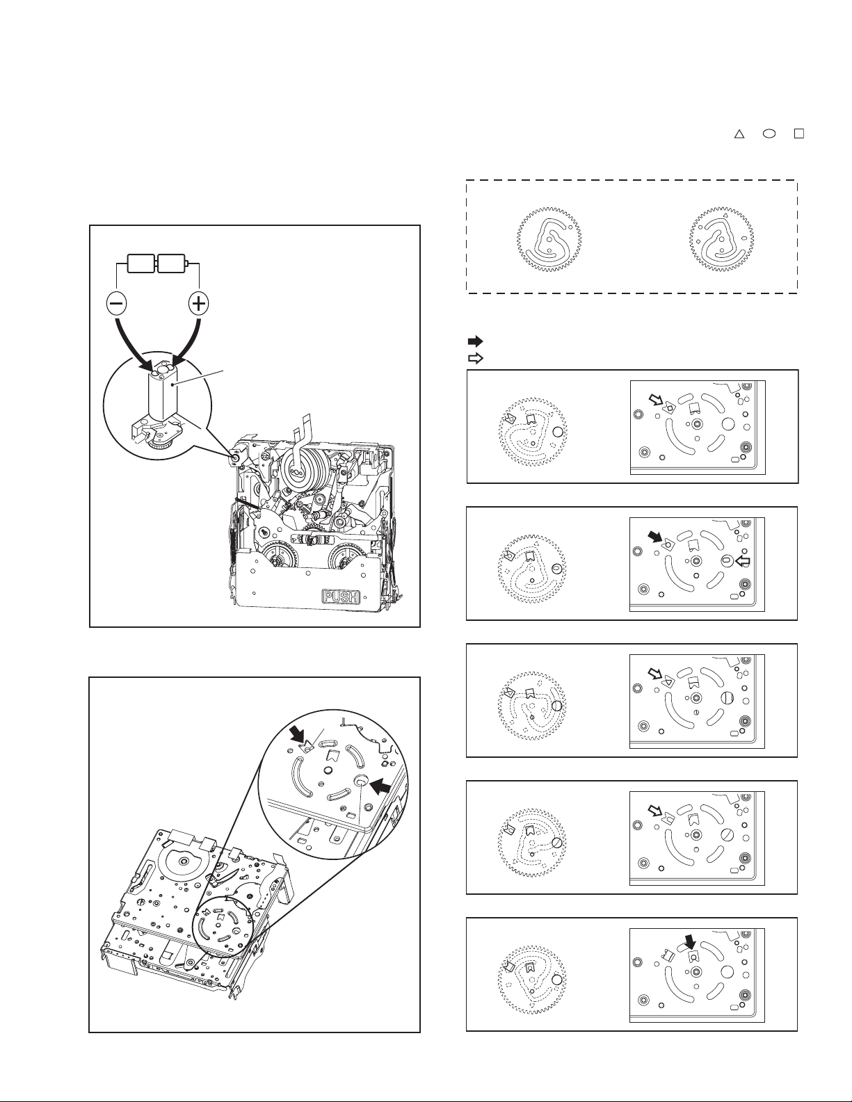
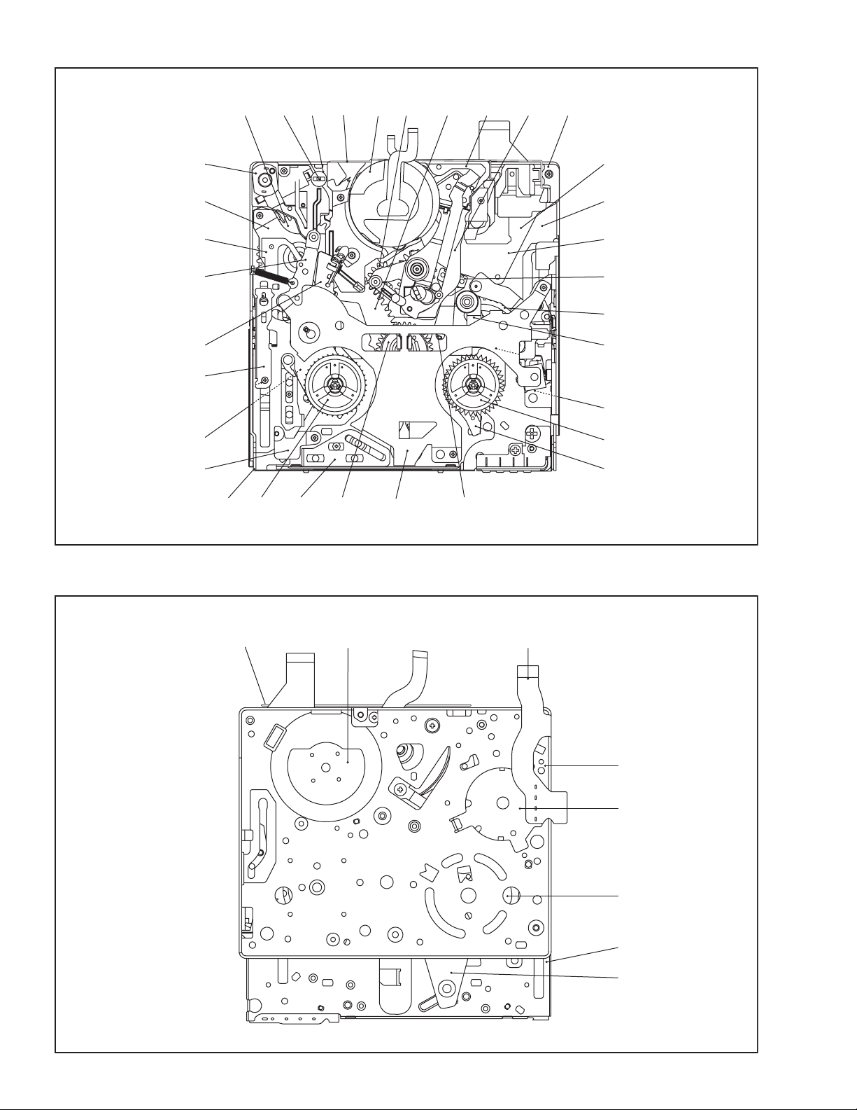
3.3.4 DISASSEMBLY AND ASSEMBLY OF MECHANISM ASSEMBLY
3.3.4.1 General statement
The mechanism should be disassembled/assembled in the
CASS IN mode (ASSEMBLY mode). (Refer to Fig. 3-3-2,3-3-5.)
When the mechanism assembly is removed from the main body,
it is generally set in the STOP mode.
After the mechanism assembly is removed from the main body,
it is required to forcibly supply 3V DC to the LOADING MOTOR
to unload, and then set the CASS IN mode.
<Mechanism assembly/Cassette housing assembly>
Fig.3-3-1
<Back side of the mechanism assembly>
Fig.3-3-2
3.3.4.2 Mechanism modes
The mechanism mode of this model is classified into five modes
as shown in Fig. 3-3-9. Each mechanism mode can be distin-
guished from others by the relative position of “ ”, “ ”, “ ”
marks on the sub cam gear to the inner or outer protrusion on the
main deck. Refer to Fig. 3-3-3 to 3-3-8 below.
Fig.3-3-3
Fig.3-3-4
Fig.3-3-5
Fig.3-3-6
Fig.3-3-7
Fig.3-3-8
LOADING MOTOR
DC3V
Back side of deck
CASS INOQFG
HOLE
Half Panch
Half Panch
Half Panch
<MAIN CAM GEAR>
TOP VIEW BOTTOM VIEW
<EJECT mode>
<Confirmation of mode>
:HOLE(Penetration)
:Half Panch
<CASS IN mode>
<SHORT FF mode>
<STOP mode>
<PLAY mode>
1-20 (No.YF228<Rev.001>)
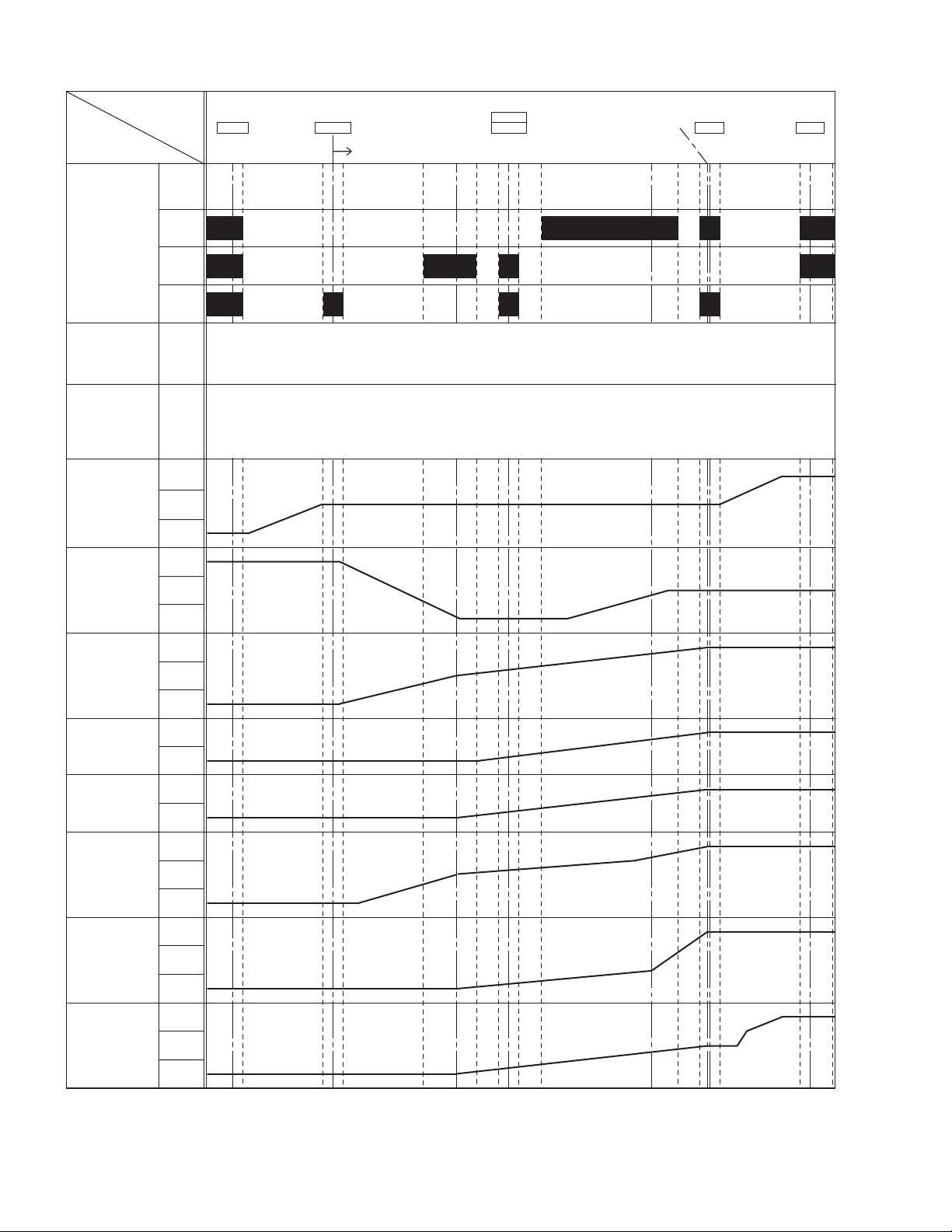
3.3.4.3 Mechanism timing chart
Fig.3-3-9
PARTS
MODE
PRESS ARM
T.C. PLATE
TENSION ARM
T5 ARM
SLIDE DECK
S1 ARM
POLE BASE
PINCH ROLLER
PRESS
OFF
EJECT
OFF1
OFF2
ON
LO2
LO1
UL
ON
OFF
LO
UL
PRESS
LO
UL
PRESS
PRESS
SLIDE
OFF
LO
UL
EJECT CAS. IN
CCW
STOP PLAYFWD
SHORT
SLIDE
START
TU. P. B
END
SLIDE
END
-46.3
o
-6.5
o
210.5
o
182.8
o
204
o
204
o
204
o
204
o
204
o
244.5
o
225.5
o
220.2
o
204
o
127.8
o
164.2
o
TOUCH
173.6
o
TOUCH
TOUCH
69
o
3.4
o
3.4
o
67.2
o
67.2
o
67.2
o
14
o
67.2
o
67.2
o
79.6
o
244.5
o
a
b
c
ROTARY
ENCODER
MAIN CAM
SUB CAM
-69.2
o
273.6
o
274.5
o
254.5
o
210.8
o
199.8
o
187.8
o
260
o
(200
o
)
190
o
(149
o
)(126.9
o
)
150
o
(193.8
o
)(164.9
o
)
(49.1
o
)
(63.8
o
)
(-50
o
)
(-65
o
)
195
o
70
o
91
o
0
o
0
o
-40
o
-52
o
(260
o
)
247
o
205.3
o
78.3
o
49.3
o
90.3
o
101.3
o
113.3
o
95.8
o
5.5
o
-5.5
o
-49.2
o
-68.4
o
0
o
-54.7
o
(No.YF228<Rev.001>)1-21
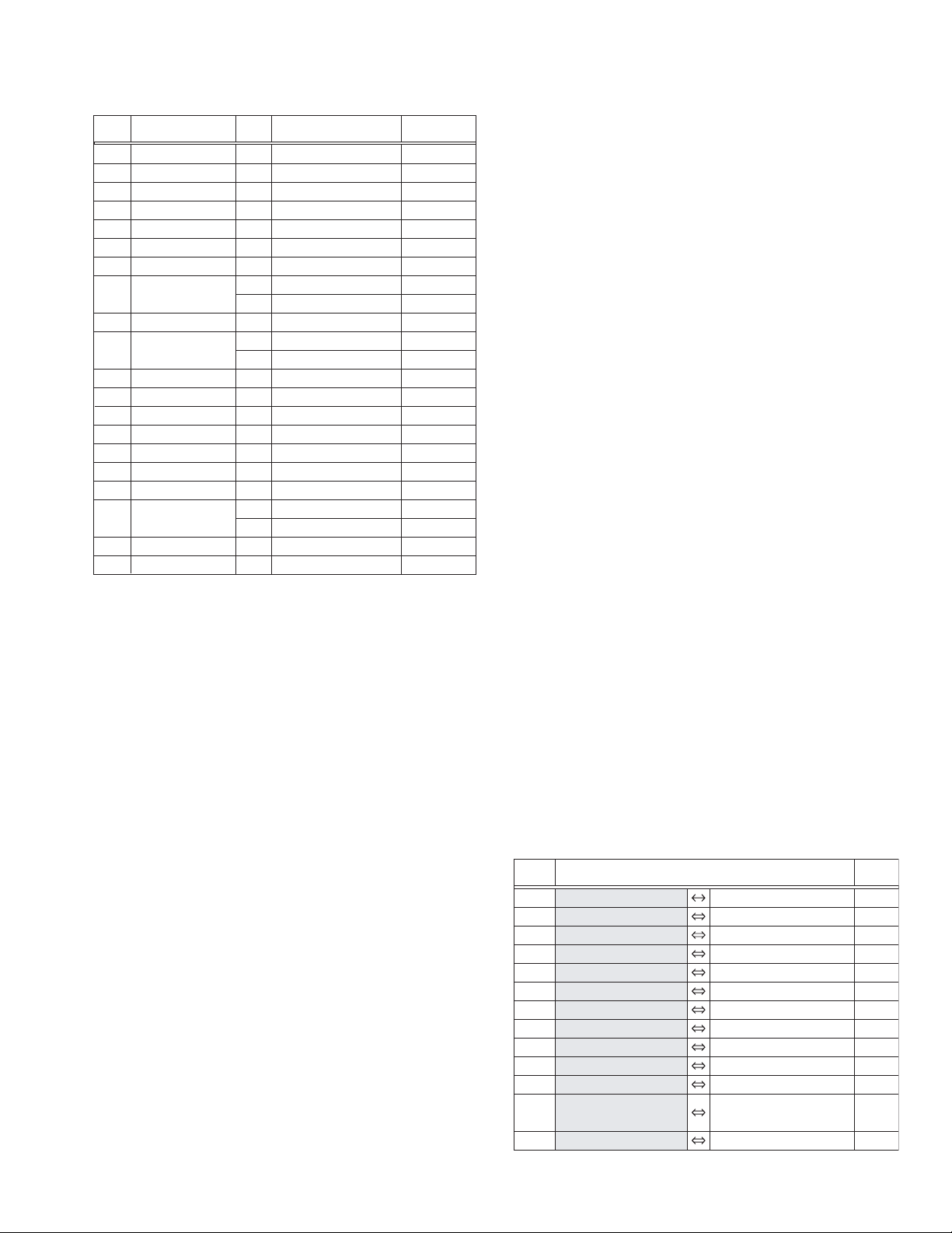
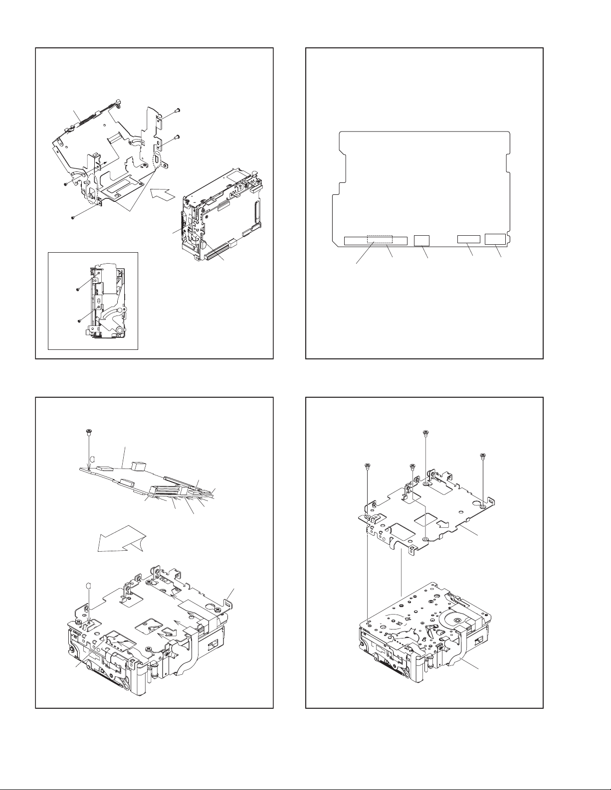
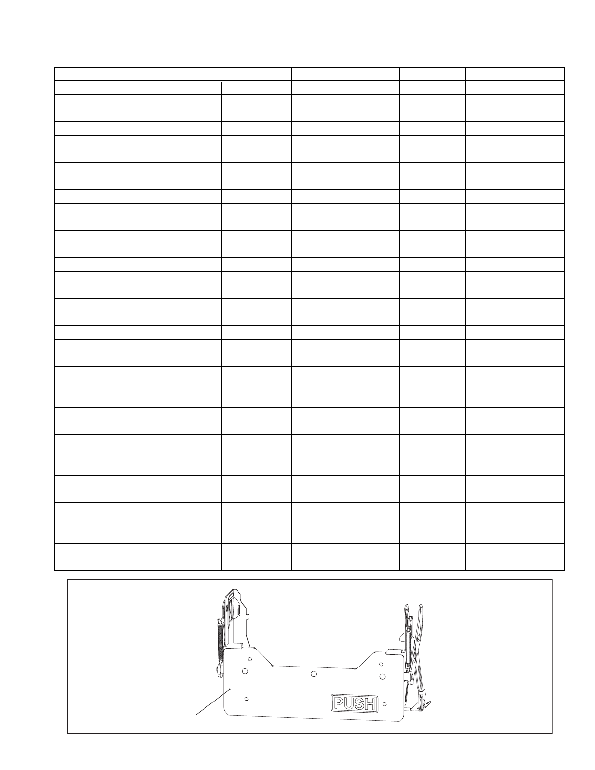
3.3.5 DISASSEMBLY PROCEDURE TABLE
MARK: # After assembly, perform adjustments.
NO. PART NAME FIG. POINT NOTE REMARKS
[1] HOUSING ASSY T 3-3-10 2(S1),L1a,b,c,d NOTE1a,b ADJUSTMENT
[2] DRUM PROTECTOR T 3-3-11 S2,L2a,b NOTE2
[3] DRUM ASSY T 3-3-11 3(S3),L3a,b NOTE3a,b #
[4] REEL COVER ASSY T 3-3-11 2(S4),2(L4a),L4b,c NOTE4
[5] IDLER ARM ASSY T 3-3-12 - -
[6] T5 ARM ASSY T 3-3-12 L6a,b NOTE6a,b ADJUSTMENT
[7] TENSION ARM ASSY T 3-3-12 L7a,S7,L7b,2(L7c) NOTE7a,b,c ADJUSTMENT/#
[8] S1 ARM ASSY T 3-3-13 L8 NOTE8 ADJUSTMENT
[9] SLIDE GUIDE PLATE T 3-3-13 S9,L9 NOTE9a,b ADJUSTMENT/#
[10] GUIDE PLATE T 3-3-13 S10,L10 - ADJUSTMENT
[11] SLIDE DECK ASSY T 3-3-14A 2(L11a),3(L11b),2(L11c) NOTE11a,b ADJUSTMENT/#
[12] CASSETTE GUIDE T 3-3-14B S12,2(L12) -
[13] PINCH ROLLER ARM ASSY T 3-3-14B L13 NOTE13a,b,c
[14] REEL DISK ASSY (SUP) T 3-3-14B L14 NOTE14a,b
[15] REEL DISK ASSY (TU) T 3-3-14B L15 NOTE15a,b,c
[16] BRAKE PLATE T 3-3-14B - NOTE16 ADJUSTMENT
[17] T. C. PLATE ASSY T 3-3-15 L17,SLIDE COLLAR1 NOTE17
[18] DRUM BASE T 3-3-15 3(S18),L18a,2(L18b) NOTE18
[19] DRIVE ARM ASSY T 3-3-15 L19,SLIDE COLLAR2 NOTE19a,b ADJUSTMENT
[20] GUIDE RAIL ASSY T 3-3-16 S20 NOTE20 ADJUSTMENT/#
[21] T5 CATCHER T 3-3-16 S21,L21 -
[22] CAPSTAN MOTOR T 3-3-16 2(S22) NOTE22
[23] REEL PULLEY T 3-3-16 - -
[24] CENTER GEAR T 3-3-16 - -
[25] MOTOR BRACKET ASSY T 3-3-17 S25 NOTE25a,b,c
[26] BELT GUIDE T 3-3-17 S26,2(L26) -
[27] GEAR COVER T 3-3-17 3(S27),L27a,b,c,d NOTE27 ADJUSTMENT
[28] PRESS ARM ASSY T 3-3-17 L28 NOTE28 ADJUSTMENT
[29] SUB CAM T 3-3-18 - NOTE29 PHASE ADJUSTMENT
[30] CONNECT GEAR T 3-3-18 - NOTE30
[31] MAIN CAM T 3-3-18 - NOTE31 PHASE ADJUSTMENT
[32] ROTARY ENCODER T 3-3-19 L32 NOTE32 PHASE ADJUSTMENT
[33] LOADING GEAR 1 T 3-3-19 - -
[34] GUIDE ROLLER (S) ASSY T 3-3-19 - NOTE34a,b #
[35] COMPRESSION SPRING T 3-3-19 - NOTE35
[36] MAIN DECK ASSY T 3-3-19 - - #
[ 1 ]
1-22 (No.YF228<Rev.001>)
[25]
[27]
[17]
[ 7 ]
[ 8 ]
[10]
[31]
[12]
[22]
[34] [35] [ 3 ]
[ 2 ][32] [33] [19] [18] [20] [21]
[14][11] [ 9 ] [ 5 ] [ 4 ] [30]
[36]
[ 6 ]
[26]
[29]
[30]
[28]
[15]
[16]
< TOP VIEW >
[25][22][ 2 ]
< BOTTOM VIEW >
[32]
[36]
[11]
[19]
[31]
(No.YF228<Rev.001>)1-23
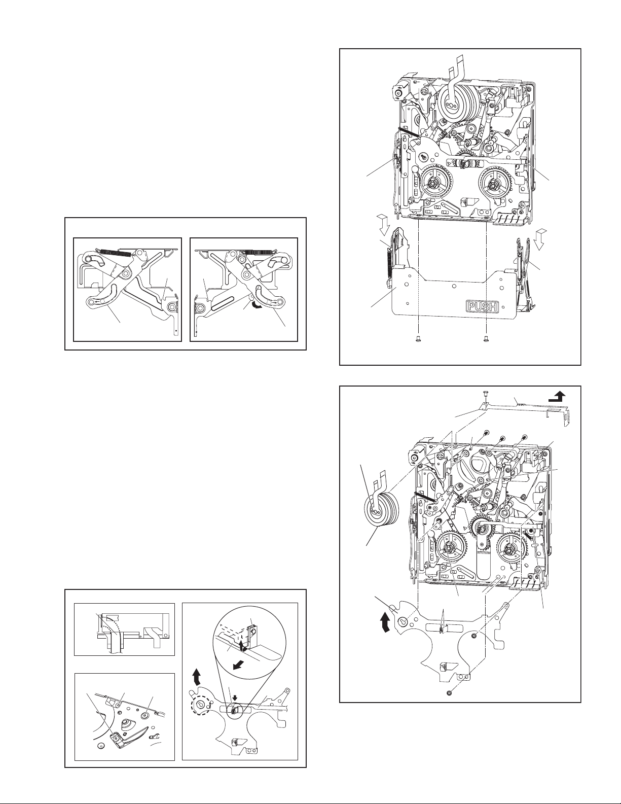
3.3.6 DISASSEMBLY/ASSEMBLY
3.3.6.1 [1] HOUSING ASSY
NOTE1a:
When disassembling/ assembling the MECHANISM ASSY,
make sure to remove the HOUSING ASSY.
When removing the HOUSING ASSY, make sure to bring the
HOUSING ASSY up either by changing the mechanism mode
to the EJECT mode, or by moving the EJECT LEVER to the di-
rection as indicated by the arrow.
During the procedure, make sure to return to the CASS IN
mode if the mode was changed.
NOTE1b:
Be careful not to damage the LEFT ARM2,RIGHT ARM2 dur-
ing work.
Fig.3-3-10
3.3.6.2 [2] DRUM PROTECTOR
[3] DRUM ASSY
[4] REEL COVER ASSY
NOTE2:
During the procedure, be careful in handling the FPC.
NOTE3a:
When removing, carefully hold the top center of the DRUM
ASSY with fingers otherwise it may possibly fall off.
NOTE3b:
Pay extra attention to the soil, dust and scratch on the surface.
During the procedure, be careful not to cut/ damage the FPC.
NOTE4:
During the procedure, remove the LED from the REEL COVER
ASSY first to set the FPC free, remove the two screws (7, 8),
then remove the REEL COVER ASSY by sliding it to the direc-
tion as indicated by the arrow.
During the procedure, be careful in handling the FPC.
Fig.3-3-11
<NOTE1a,b>
LEFT ARM2
RIGHT ARM2
L1a L1b
EJECT
LEVER
1
(S1)
2
(S1)
[ 1 ]
L1c
L1d
NOTE1b
NOTE1a
NOTE1b
RIGHT
ARM2
LEFT
ARM2
FPC
FPC
LED
LED
< bottom side >
<NOTE3a>
<NOTE2> <NOTE4>
4
(S3)
5
(S3)
6
(S3)
DRUM
SIDE
FPC
L2a
L4c
L4b
L4a
FPC
NOTE4
8
(S4)
7
(S4)
4
(S3)
5
(S3)
6
(S3)
[3]
[2]
[4]
NOTE3b
NOTE3a
NOTE2
L3a
L3b
L2b
3
(S2)
1-24 (No.YF228<Rev.001>)
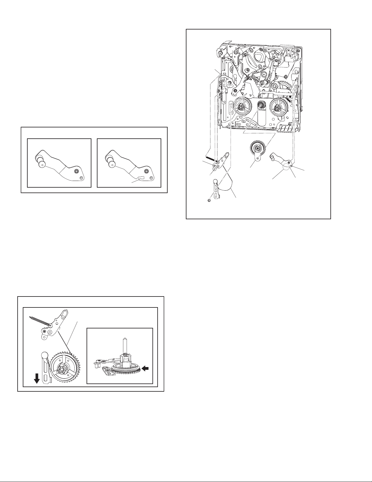
3.3.6.3 [5] IDLER ARM ASSY
[6] T5 ARM ASSY
[7] TENSION ARM ASSY
NOTE6a:
There are two types of the T5 ARM ASSY. They are different
in shape. The old type is without a hook and the new type is
with a hook.
When an old type is replaced by a new type, replace the
PINCH ROLLER ARM ASSY at the same time as the proper
combination of the parts is required.
When removing, remove the spring from the hook first if there
is a hook.
NOTE6b:
When mounting, pay attention to the correct positioning.
NOTE7a:
During the procedure, be careful in handling the TENSION
BAND.
NOTE7b:
When mounting, attach the TENSION BAND along the groove
of the gear.
NOTE7c:
When mounting, pay attention to the correct positioning.
When mounting, attach the TENSION ARM ASSY with the
plate moved to the direction as indicated by the arrow.
If the plate is moved to the other direction, the TENSION
BAND may break during the operation check as there is too
much tension.
After the mounting, adjust the TENSION ARM ASSY.
Fig.3-3-12
L6a
<NOTE6a>
< OLD TYPE > < NEW TYPE >
< FRONT >
< TOP >
<NOTE7b,c>
TENSION BAND
[5]
[6]
L6b
NOTE6b
9
(S7)
[7]
TENSION BAND
NOTE7a
NOTE6a
L7b
L7a
L7c
L7c
L7c
(No.YF228<Rev.001>)1-25
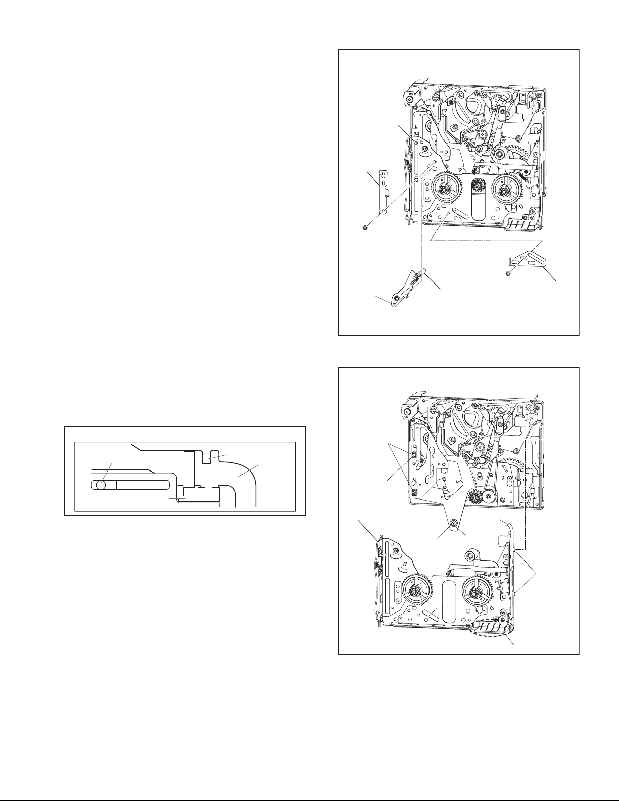
3.3.6.4 [8] S1 ARM ASSY
[9] SLIDE GUIDE PLATE
[10] GUIDE PLATE
NOTE8:
When mounting, pay attention to the correct positioning.
NOTE9a:
When mounting, pay attention to the correct positioning.
NOTE9b:
After attachment, adjust the SLIDE GUIDE PLATE.
Fig.3-3-13
3.3.6.5 [11] SLIDE DECK ASSY
NOTE11a:
When removing, set the FPC free first.
During the procedure, be careful not to cut the FPC.
NOTE11b:
During the procedure, be careful in handling.
Fig.3-3-14A
11
(S10)
10
(S9)
[10]
[9]
[8]
L8
NOTE8
NOTE9a,b
L10
L9
<NOTE11a>
L11a
L11c
FPC
T5 CATCHER
[11]
L11b
L11a
NOTE11a
L11b
L11c
FPC
NOTE11b
MIC SW
Loading...