


 Loading...
COMPACT COMPONENT SYSTEM
FS-SD550/FS-SD770/FS-SD990
Consist of CA-FSSD550 and SP-FSSD550
Consist of CA-FSSD770 and SP-FSSD770
Consist of CA-FSSD990 and SP-FSSD990
FS-SD550
FS-SD770, FS-SD990
INSTRUCTIONS
For Customer Use:
Enter below the Model No. and Serial No. which are located either on the rear, bottom or side of the cabinet. Retain this information for future reference.
Model No.
Serial No.
GNT0008-001A [J]
Warnings, Cautions and Others
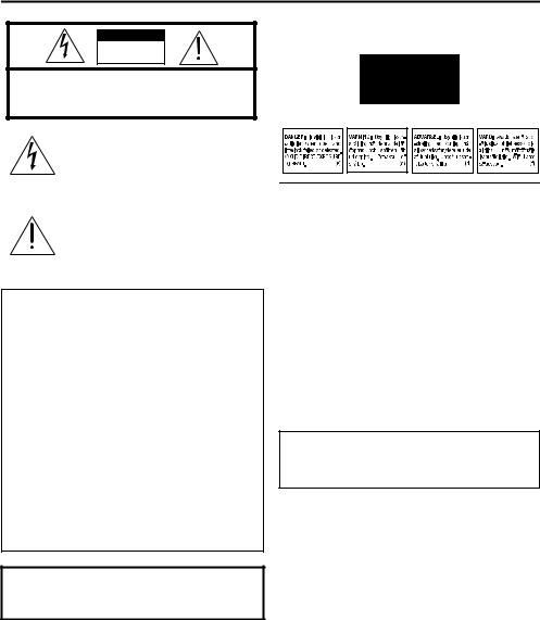
CAUTION
RISK OF ELECTRIC
SHOCK
DO NOT OPEN
CAUTION: TO REDUCE THE RISK OF ELECTRIC SHOCK DO NOT REMOVE COVER (OR BACK)
NO USER SERVICEABLE PARTS INSIDE
REFER SERVICING TO QUALIFIED SERVICE PERSONNEL.
The lightning flash with arrowhead symbol, within an equilateral triangle is intended to alert the user to the presence of uninsulated “dangerous voltage” within the product’s enclosure that may be of sufficient magnitude to constitute a risk of electric shock to persons.
The exclamation point within an equilateral triangle is intended to alert the user to the presence of important operating and maintenance (servicing) instructions in the literature accompanying the appliance.
For U.S.A
This equipment has been tested and found to comply with the limits for a Class B digital device, pursuant to Part 15 of the FCC Rules. These limits are designed to provide reasonable protection against harmful interference in a residential installation. This equipment generates, uses, and can radiate radio frequency energy and, if not installed and used in accordance with the instructions, may cause harmful interference to radio communications. However, there is no guarantee that interference will not occur in a particular installation. If this equipment does cause harmful interference to radio or television reception, which can be determined by turning the equipment off and on, the user is encouraged to try to correct the interference by one or more of the following measures:
–Reorient or relocate the receiving antenna.
–Increase the separation between the equipment and receiver.
–Connect the equipment into an outlet on a circuit different from that to which the receiver is connected.
–Consult the dealer or an experienced radio/TV technician for help.
WARNING: TO REDUCE THE RISK OF FIRE OR ELECTRIC SHOCK, DO NOT EXPOSE THIS APPLIANCE TO RAIN OR MOISTURE.
IMPORTANT FOR LASER PRODUCTS
REPRODUCTION OF LABELS
1. CLASSIFICATION LABEL, PLACED ON EXTERIOR SURFACE
CLASS 1
LASER PRODUCT
2. WARNING LABEL, PLACED INSIDE THE UNIT
1.CLASS 1 LASER PRODUCT
2.DANGER: Invisible laser radiation when open and interlock failed or defeated. Avoid direct exposure to beam.
3.CAUTION: Do not open the top cover. There are no user serviceable parts inside the unit; leave all servicing to qualitied service personnel.
CAUTION
To reduce the risk of electrical shocks, fire, etc.: 1 Do not remove screws, covers or cabinet.
2. Do not expose this appliance to rain or moisture.
CAUTION
■About the Internal Cooling Fan
This unit includes an internal cooling fan, so as to allow for high-power operation within a small space.
This fan comes on when the sound level is set high, and may also come on even at low sound levels if the internal temperature rises. To ensure effective fan operation, please leave at least 15cm clearance between the rear of the unit and the wall, and at least 1cm clearance on each side of the unit.
Caution — POWER switch!
Disconnect the mains plug to shut the power off completely. The POWER switch in any position does not disconnect the mains line. The power can be remote controlled.
G-1
Introduction
Thank you for purchasing the JVC Compact Component System.
We hope it will be a valued addition to your home, giving you years of enjoyment.
Be sure to read this instruction manual carefully before operating your new stereo system.
In it you will find all the information you need to set up and use the system.
If you have a query that is not answered by the manual, please contact your dealer.
Features
Here are some of the things that make your System both powerful and simple to use.
■The controls and operations have been redesigned to make them very easy to use, freeing you to just enjoy the music.
•With JVC’s COMPU PLAY you can turn on the System and automatically start the Radio or CD Player with a single touch.
■The System incorporates Active Hyper Bass PRO circuitry to faithfully reproduce low frequency sounds.
■A 45-station preset capability (30 FM and 15 AM) in addition to auto-seek and manual tuning.
■CD options that include repeat, random and program play.
■Timer functions; Daily Timer and Sleep Timer.
■You can connect various external units, such as an MD recorder.
■The system can play CD-R and CD-RW after they have been finalized.
■You can play back your original CD-R or CD-RW recorded in Music CD format. (However they may not be played back depending on their characteristics or recording conditions.)
How This Manual Is Organized
•Basic information that is the same for many different functions - e.g. setting the volume - is given in the section ‘Basic Operations’, and not repeated under each function.
•The names of buttons/controls and display messages are written in all capital letters: e.g. FM/AM, “NO DISC”.
•System functions are written with an initial capital letter only: e.g. Normal Play.
Use the table of contents to look up specific information you require.
We have enjoyed making this manual for you, and hope it serves you in enjoying the many features built into your System.
WARNINGS
•DO NOT PUT ANYTHING ON THE TOP COVER. IF THE SYSTEM IS OPERATED WITH SOMETHING PUT ON THE TOP COVER, IT WILL BE DAMAGED WHEN YOU TRY TO OPEN THE TOP COVER.
•NEVER REMOVE THE TOP COVER FROM THE UNIT. SERIOUS INJURY MAY OCCUR IF THE SYSTEM IS OPERATED WITHOUT THE TOP COVER.
IMPORTANT CAUTIONS
1Installation of the System
•Select a place which is level, dry and neither too hot nor too cold. (Between 5°C and 35°C or 41°F and 95°F.)
•Leave sufficient distance between the System and a TV.
•Do not use the System in a place subject to vibrations.
2Power cord
•Do not handle the power cord with wet hands!
•Some power is always consumed as long as the power cord is connected to the wall outlet.
•When unplugging the System from the wall outlet, always pull the plug, not the power cord.
3Malfunctions, etc.
•There are no user serviceable parts inside. In case of system failure, unplug the power cord and consult your dealer.
•Do not insert any metallic object into the System.
•Do not insert your hand between the Top Cover and the main body when the Top Cover is being closed.
1

Table of Contents
Introduction ........................................................................................................ |
1 |
Features ...................................................................................................................................... |
1 |
How This Manual Is Organized ................................................................................................. |
1 |
WARNINGS .............................................................................................................................. |
1 |
IMPORTANT CAUTIONS ....................................................................................................... |
1 |
Getting Started ................................................................................................... |
3 |
Accessories................................................................................................................................. |
3 |
How To Put Batteries In the Remote Control ............................................................................ |
3 |
Using the Remote Control.......................................................................................................... |
3 |
Connecting the FM Antenna ...................................................................................................... |
4 |
Connecting the AM Antenna...................................................................................................... |
5 |
Connecting the Speakers ............................................................................................................ |
6 |
Connecting a Subwoofer ............................................................................................................ |
7 |
Connecting External Equipment ................................................................................................ |
7 |
Connecting an MD Recorder, etc (Digital Output) .................................................................... |
7 |
Connecting the AC Power Cord................................................................................................. |
8 |
COMPU Play.............................................................................................................................. |
8 |
Automatic Power On .................................................................................................................. |
8 |
Basic Operations ............................................................................................... |
9 |
Turning the Power On and Off................................................................................................... |
9 |
Adjusting the Brightness (DIMMER) ........................................................................................ |
9 |
Adjusting the Volume ................................................................................................................ |
9 |
Fade-out Muting (FADE MUTING)........................................................................................ |
10 |
Reinforcing the Bass Sound (AHB PRO) ................................................................................ |
10 |
Tone Control (BASS/TREBLE)............................................................................................... |
10 |
Showing the Time (CLOCK/DISPLAY) ................................................................................. |
10 |
Sliding the Top Cover (DOOR SLIDE) ................................................................................... |
10 |
Using the Tuner................................................................................................ |
11 |
Tuning In a Station ................................................................................................................... |
11 |
Presetting Stations .................................................................................................................... |
12 |
Auto Presetting ......................................................................................................................... |
12 |
To Change the FM Reception Mode ........................................................................................ |
12 |
Using the CD Player......................................................................................... |
13 |
To Insert a CD .......................................................................................................................... |
13 |
To Unload a CD ....................................................................................................................... |
14 |
Basics of Using the CD Player-Normal Play ........................................................................... |
14 |
Programming the Playing Order of the Tracks ........................................................................ |
14 |
Random Play ............................................................................................................................ |
15 |
Repeating Tracks...................................................................................................................... |
15 |
Using External Equipments ............................................................................ |
16 |
Listening to External Equipment.............................................................................................. |
16 |
Recording the System’s Source to External Equipment .......................................................... |
16 |
Using the Timers .............................................................................................. |
17 |
Setting the Clock ...................................................................................................................... |
17 |
Setting the Daily Timer ............................................................................................................ |
17 |
Setting the SLEEP Timer ......................................................................................................... |
19 |
Care And Maintenance .................................................................................... |
20 |
Troubleshooting............................................................................................... |
21 |
Specifications................................................................................................... |
22 |
2
Getting Started
Accessories
Make sure that you have all of the following items, which are supplied with the System.
Power Cord (1)
AM Loop Antenna (1)
Remote Control (1)
Batteries (2)
FM Wire Antenna (1)
Speaker Cords (2)
If any of these items are missing, contact your dealer immediately.
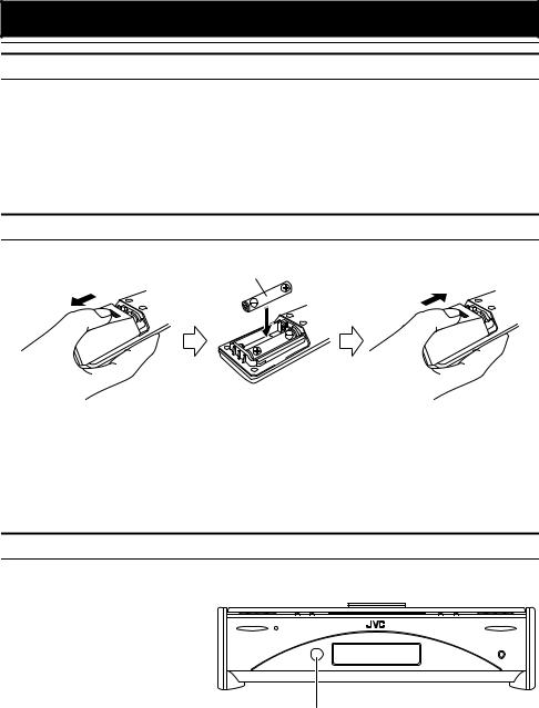
How To Put Batteries In the Remote Control
Match the polarity (+ and –) on the batteries with the + and – markings in the battery compartment.
R6P(SUM-3)/AA(15F)
 CAUTION:
• Handle batteries properly.
■To avoid battery leakage or explosion:
•Remove batteries when the Remote Control will not be used for a long time.
•When you need to replace the batteries, replace both batteries at the same time with new ones.
•Do not use an old battery with a new one.
•Do not use different types of batteries together.
Using the Remote Control
The Remote Control makes it easy to use many of the functions of the System from a distance of up to 7m (23 feet) away. You need to point the Remote Control at the remote sensor on the System’s front panel.
POWER |
STANDBY/ON |
OPEN/CLOSE |
|
|
PHONES |
Remote sensor
3
Getting Started
 CAUTION:
• Make all connections before plugging the System into an AC power outlet.
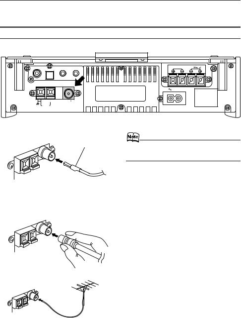
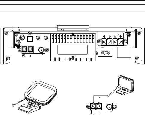
Connecting the FM Antenna
Rear Panel of the Unit
SUB WOOFER |
|
OUT |
IN |
|
CD DIGITAL OUT |
||
|
|
|
MD / AUX
ANTENNA |
AM EXT |
FM(75 ) |
|
COAXIAL |
AM LOOP
SPEAKERS IMPEDANCE 4 |
16 |
R |
L |
AC IN
Using the Supplied Wire Antenna
FM wire antenna (supplied)
Using the Coaxial Type Connector
(Not Supplied)
A 75-ohm antenna with coaxial type connector should be connected to the FM 75-ohm COAXIAL terminal.
If reception is poor, connect the outdoor antenna.
FM outdoor antenna
(Not supplied)
Coaxial cable
•Before attaching a 75 ohm coaxial lead (the kind with a round wire going to an outdoor antenna), disconnect the supplied FM Wire Antenna.
4
Getting Started
Connecting the AM Antenna
Rear Panel of the Unit
SUB WOOFER |
|
OUT |
IN |
|
CD DIGITAL OUT |
||
|
|
|
MD / AUX
ANTENNA |
AM EXT |
FM(75 ) |
|
COAXIAL |
AM LOOP
SPEAKERS IMPEDANCE 4 |
16 |
R |
L |
AC IN
AM loop antenna (Supplied)
Attach the AM loop to its base by snapping the tabs on the loop into the slot in the base.
ANTENNA
AM EXT |
FM(75 ) |
COAXIAL
AM LOOP
Turn the loop until you have the best reception.
 CAUTION:
•To avoid noise, keep antennas away from the System, the connecting cord and the AC power cord.
5
Getting Started
 CAUTION:
• Make all connections before plugging the System into an AC power outlet.
Connecting the Speakers
1.Open each of the terminals to connect the speaker wire leads.
2.Connect the speaker cords between the Speaker terminals of the Unit and the terminals of the Speakers. Connect the cords with a black line to the (–) terminals and cords without a black line to the (+) terminals.
3.Close each of the terminals to securely connect the cords.
Right side (rear view) |
Left side (rear view) |
Marked with a black line
SPEAKERS IMPEDANCE 4  16
16
R |
L |
• Since both speakers are the same, you can put either one to the right or left side.
 CAUTION:
•A TV may display irregular colors if located near the speakers. If this happens, set the speakers away from the TV.
Removing the speaker grilles
The speaker grilles can be moved.
When removing:
1.Pull the top forwards you with your fingers.
2.Also pull the bottom towords you.
•When removing the speaker grille from the FSSD990’s speaker, be careful not to damage the cabinet.
When attaching the speaker grille:
(FS-SD550) (FS-SD770 and FS-SD990)
(FS-SD550) (FS-SD770 and FS-SD990)
Speaker |
Speaker |
grille |
|
|
grille |
6
Getting Started
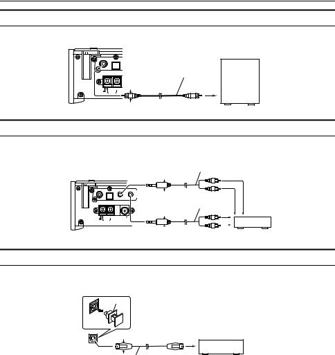
Connecting a Subwoofer
Connect a signal cord (not supplied) between the System’s SUBWOOFER terminal and the input terminal of an external subwoofer.
SUB WOOFER |
CD DIGITAL OUT |
OUT |
IN |
MD / AUX
ANTENNA |
|
|
AM EXT |
FM11mm(75Max/ ) |
|
AM LOOP |
* |
COAXIAL |
Powered Subwoofer (not supplied)
Signal cord (not supplied)
Max.
* Use the plug whose diameter is 11mm or less.
Connecting External Equipment
Connect signal cords (not supplied) between the System’s MD/AUX-OUT/IN terminals and the output/input terminals of the external MD recorder, tape deck, etc.
You can then listen to the external source through the System or record the System’s CD player or tuner to the external unit.
SUB WOOFER |
CD DIGITAL OUT |
OUT |
IN |
MD / AUX
ANTENNA |
AM EXT |
FM(75 ) |
|
COAXIAL |
AM LOOP
Signal cord (not supplied)
* 11mm Max. |
|
|
Stereo mini-plug |
Pin-plug x 2 |
|
|
|
|
Signal cord (not supplied) |
MD recorder or tape |
|
* 11mm Max. |
|
deck (not supplied) |
|
|
|
|
|
|
|
|
Stereo mini-plug |
Pin-plug x 2 |
|
|
|
|||
|
|
|
|||||
* Use the plug whose diameter is 11mm or less. |
|
|
|
|
|
|
|
Connecting an MD Recorder, etc (Digital Output)
Unplug the cap and connect an optical digital cord (not supplied) between the System’s CD DIGITAL OUT terminal and the input terminal of the MD recorder, etc.
You can record the digital output signal from the System’s CD Player to the MD recorder, etc.
Cap
CD DIGITAL OUT |
*11mm Max. |
MD recorder, etc. (not supplied) |
|
||
|
|
Optical digital cord (not supplied) * Use the plug whose diameter is 11mm or less.
7
Loading...