


SUBWOOFER
CAISSON DE GRAVE
CS-AW7020 CS-AW7040 CS-AW7220 CS-AW7240
ESPAŃOL FRANÇAIS ENGLISH
For Customer Use:
Enter below the Model No, and Serial No, which is located either on the rear or bottom of the speaker unit. Retain this information for future reference.
Model No.
INSTRUCTION MANUAL Serial No.
MANUEL D'INSTRUCTIONS |
LVT1743-001A |
MANUAL DE INSTRUCCIONES |
|
ENGLISH
Thank you for purchasing the ARSENAL Car Stereo Speaker. These Speakers can be mounted in the trunk of your vehicle. For the secure installation and perfect operation of your speakers, please read the following carefully.
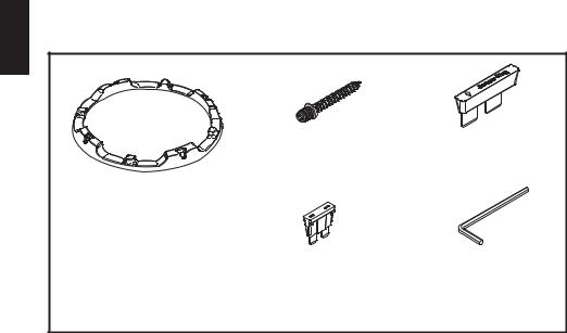
Parts
2. Screw x 10 |
3. Jump |
1. Grille
4. Fuse (10A) x 2 |
5. Hexagon socket |
|
screw keys |
For proper installation and use
1.Before connecting the speakers to the amplifier, confirm that the power has been turned off. The click noise generated by the connection if the power is on may damage the speakers.
2.The amplifier and speakers should be connected between corresponding terminals, i.e. left to left, and right to right, as well as "+" to "+", and "–" to "–". Connection with reversed polarity will degrade the quality of stereo reproduction.
3.Do not subject the speakers to excessive input. The power handling capacity of the CS-AW7020/CS-AW7040/CS-AW7220/CS-AW7240 is 600 watts (R.M.S. MUSIC POWER). Any excessive input may damage the speakers.
4.The CS-AW7020/CS-AW7040/CS-AW7220/CS-AW7240 has an impedance of 2Ω ,4Ω,8Ω. Make sure that the output impedance of the amplifier's speaker terminal is rated at 2Ω,4Ω,8Ω.
5.When cleaning the speakers, use a soft cloth and wipe the surface gently. Do not apply thinner or solvent.
6.Be sure to carefully follow the instructions for:
Cable Connections
Fuse Replacement
Switching the Impedance Selector
Subwoofer Mounting and Smart Trim Ring Installation
Consult Page 19 of this Instruction Manual for details on these procedures.
- 2 -
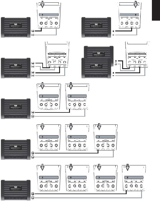
Dual 4 Ω Application Diagrams
|
|
JUMPER |
|
|
JUMPER |
1 |
Mono Amplifier |
|
1 |
Mono Amplifier |
|
1 |
Subwoofer |
|
1 |
Subwoofer |
|
Jumper set to Series |
|
Jumper set to Parallel |
|
||
8Ω(4Ω+4Ω) Load |
SERIES PARALLEL |
8Ω(4Ω+4Ω) Load |
SERIES PARALLEL |
||
|
|
Jumper Plug |
|
|
Jumper Plug |
1 2ch Amplifier
1 Subwoofer Jumper is Removed 4Ω Load
1 Mono Amplifier
2 Subwoofers Jumper set to Series
Subwoofers wired in Parallel 4Ω Load
Input |
- |
Bi-Amp |
+ |
Input |
+ |
Only |
- |
Mono |
4Ω |
4Ω |
|
|
|
|
|
||
8Ω |
|
|
|
|
|
*JUMPER is Removed |
|||
|
SERIES |
PARALLEL |
||
Stereo |
Input |
- |
Bi-Amp |
Input |
+ |
Only + |
- |
||
4Ω 2-Chan |
|
|
|
|
JUMPER |
|
|
JUMPER |
|
Input |
|
Bi-Amp |
+ |
Input |
|
+ |
- Only |
- |
|||
Mono |
|
4Ω |
|
|
4Ω |
|
|
|
|||
2Ω |
|
|
|
|
|
*JUMPER is Removed
Bi-Amp Configuration 2 Mono Amplifiers 1 Subwoofer Jumper is Removed 4Ω Load
SERIES PARALLEL
Mono
Input |
- |
Bi-Amp |
+ |
Input |
+ |
Only |
- |
||
4Ω |
|
|
|
|
Mono
 4Ω
4Ω
SERIES PARALLEL |
SERIES PARALLEL |
Jumper Plug |
Jumper Plug |
|
Input |
|
Bi-Amp |
+ |
Input |
Input |
|
Bi-Amp |
Input |
|
|
|
|
|
|
|
|
|
|||||
|
+ |
- Only |
- |
+ |
- Only + |
- |
|
|
|
|
|
|
|
|
|
|
|||||||
|
Mono |
|
|
4Ω 8Ω |
|
4Ω |
|
|
|
4Ω 8Ω 4Ω |
|
|
|
|
|
|
|
|
|
|
|
||
|
|
|
|
|
|
|
|
|
|
|
|
|
|
|
|
|
|||||||
|
|
|
|
|
|
|
|
|
|
|
|
|
|
|
|
|
|
|
|||||
|
4Ω |
|
|
|
|
|
|
|
|
|
|
|
|
|
|
|
|
|
|
|
|
||
|
JUMPER |
|
|
|
JUMPER |
|
|
JUMPER |
|
|
|
|
|
||||||||||
1 Mono Amplifier |
|
|
|
|
|
|
|
|
|
|
|
|
|
|
|
|
|
|
|
|
|
|
|
3 Subwoofers |
|
|
|
|
|
|
|
|
|
|
|
|
|
|
|
|
|
|
|
|
|
|
|
Jumper set to Series |
|
|
|
|
|
|
|
|
|
|
|
|
|
|
|
|
|
|
|
|
|
|
|
Subwoofers wired in Parallel |
SERIES |
PARALLEL |
SERIES |
PARALLEL |
SERIES |
PARALLEL |
|
|
|
||||||||||||||
2.6Ω Load |
|
|
|
Jumper Plug |
|
|
Jumper Plug |
|
|
Jumper Plug |
|
|
|
||||||||||
|
Input |
|
Bi-Amp |
+ |
Input |
Input |
|
Bi-Amp |
Input |
Input |
|
Bi-Amp |
Input |
|
|
|
|||||||
|
+ |
- Only |
- |
+ |
- Only + |
- |
|
+ |
- Only + |
- |
|
|
|
||||||||||
|
Mono |
|
|
4Ω 8Ω |
|
4Ω |
|
|
|
4Ω 8Ω 4Ω |
|
|
|
|
4Ω 8Ω 4Ω |
|
|
|
|
|
|||
|
|
|
|
|
|
|
|
|
|
|
|
|
|
|
|||||||||
|
|
|
|
|
|
|
|
|
|
|
|
|
|
|
|
|
|||||||
|
2.6Ω |
|
|
|
|
|
|
|
|
|
|
|
|
|
|
|
|
|
|
|
|
||
|
JUMPER |
|
|
|
JUMPER |
|
|
JUMPER |
|
|
JUMPER |
|
|||||||||||
1 Mono Amplifier |
|
|
|
|
|
|
|
|
|
|
|
|
|
|
|
|
|
|
|
|
|
|
|
4 Subwoofers |
|
|
|
|
|
|
|
|
|
|
|
|
|
|
|
|
|
|
|
|
|
|
|
Jumper set to Series |
|
|
|
|
|
|
|
|
|
|
|
|
|
|
|
|
|
|
|
|
|
|
|
Subwoofers wired in Parallel |
SERIES |
PARALLEL |
SERIES |
PARALLEL |
SERIES |
PARALLEL |
SERIES PARALLEL |
||||||||||||||||
2Ω Load |
|
|
|
Jumper Plug |
|
|
Jumper Plug |
|
|
Jumper Plug |
|
Jumper Plug |
|||||||||||
|
Input |
|
Bi-Amp |
+ |
Input |
Input |
|
Bi-Amp |
Input |
Input |
|
Bi-Amp |
Input |
Input |
Bi-Amp |
Input |
|||||||
|
+ |
- Only |
- |
+ |
- Only + |
- |
|
+ |
- Only + |
- |
+ |
- Only + |
- |
||||||||||
|
Mono |
|
|
4Ω 8Ω |
|
4Ω |
|
|
|
4Ω 8Ω 4Ω |
|
|
|
|
4Ω 8Ω 4Ω |
|
|
|
4Ω 8Ω 4Ω |
||||
|
|
|
|
|
|
|
|
|
|
|
|
|
|||||||||||
|
|
|
|
|
|
|
|
|
|
|
|
|
|
|
|||||||||
|
2Ω |
|
|
|
|
|
|
|
|
|
|
|
|
|
|
|
|
|
|
|
|
||
ENGLISH
- 3 -

ENGLISH
Dual 2 Ω Application Diagrams
|
|
JUMPER |
|
|
JUMPER |
1 |
Mono Amplifier |
|
1 |
Mono Amplifier |
|
1 |
Subwoofer |
|
1 |
Subwoofer |
|
Jumper set to Series |
|
Jumper set to Parallel |
|
||
4Ω(2Ω+2Ω) Load |
SERIES PARALLEL |
4Ω(2Ω+2Ω) Load |
SERIES PARALLEL |
||
|
|
Jumper Plug |
|
|
JumperPlug |
1 2ch Amplifier
1 Subwoofer Jumper is Removed 2Ω Load
1 Mono Amplifier
2 Subwoofers Jumper set to Series
Subwoofers wired in Parallel 2Ω Load
Input |
- |
Bi-Amp |
+ |
Input |
+ |
Only |
- |
Mono |
2Ω |
2Ω |
|
|
|
|
|
||
4Ω |
|
|
|
|
|
*JUMPER is Removed |
|||
|
SERIES |
PARALLEL |
||
Stereo |
Input |
- |
Bi-Amp |
Input |
+ |
Only + |
- |
||
2Ω 2-Chan |
|
|
|
|
JUMPER |
|
|
JUMPER |
|
Input |
|
Bi-Amp |
+ |
Input |
|
+ |
- Only |
- |
|||
Mono |
|
2Ω |
|
|
2Ω |
|
|
|
|||
1Ω |
|
|
|
|
|
*JUMPER is Removed
Bi-Amp Configuration 2 Mono Amplifiers 1 Subwoofer Jumper is Removed 2Ω Load
SERIES PARALLEL
Mono
Input |
- |
Bi-Amp |
+ |
Input |
+ |
Only |
- |
||
2Ω |
|
|
|
|
Mono
 2Ω
2Ω
SERIES PARALLEL |
SERIES PARALLEL |
Jumper Plug |
Jumper Plug |
|
Input |
|
Bi-Amp |
+ |
Input |
Input |
|
Bi-Amp |
Input |
|
|
|
|
|
|
|
|
|
|||||
|
+ |
- Only |
- |
+ |
- Only + |
- |
|
|
|
|
|
|
|
|
|
|
|||||||
|
Mono |
|
|
2Ω 4Ω |
|
2Ω |
|
|
|
2Ω 4Ω 2Ω |
|
|
|
|
|
|
|
|
|
|
|
||
|
|
|
|
|
|
|
|
|
|
|
|
|
|
|
|
|
|||||||
|
|
|
|
|
|
|
|
|
|
|
|
|
|
|
|
|
|
|
|||||
|
2Ω |
|
|
|
|
|
|
|
|
|
|
|
|
|
|
|
|
|
|
|
|
||
|
JUMPER |
|
|
|
JUMPER |
|
|
JUMPER |
|
|
|
|
|
||||||||||
1 Mono Amplifier |
|
|
|
|
|
|
|
|
|
|
|
|
|
|
|
|
|
|
|
|
|
|
|
3 Subwoofers |
|
|
|
|
|
|
|
|
|
|
|
|
|
|
|
|
|
|
|
|
|
|
|
Jumper set to Series |
|
|
|
|
|
|
|
|
|
|
|
|
|
|
|
|
|
|
|
|
|
|
|
Subwoofers wired in Parallel |
SERIES |
PARALLEL |
SERIES |
PARALLEL |
SERIES |
PARALLEL |
|
|
|
||||||||||||||
1.3Ω Load |
|
|
|
Jumper Plug |
|
|
Jumper Plug |
|
|
Jumper Plug |
|
|
|
||||||||||
|
Input |
|
Bi-Amp |
+ |
Input |
Input |
|
Bi-Amp |
Input |
Input |
|
Bi-Amp |
Input |
|
|
|
|||||||
|
+ |
- Only |
- |
+ |
- Only + |
- |
|
+ |
- Only + |
- |
|
|
|
||||||||||
|
Mono |
|
|
2Ω 4Ω |
|
2Ω |
|
|
|
2Ω 4Ω 2Ω |
|
|
|
|
2Ω 4Ω 2Ω |
|
|
|
|
|
|||
|
|
|
|
|
|
|
|
|
|
|
|
|
|
|
|||||||||
|
|
|
|
|
|
|
|
|
|
|
|
|
|
|
|
|
|||||||
|
1.3Ω |
|
|
|
|
|
|
|
|
|
|
|
|
|
|
|
|
|
|
|
|
||
|
JUMPER |
|
|
|
JUMPER |
|
|
JUMPER |
|
|
JUMPER |
|
|||||||||||
1 Mono Amplifier |
|
|
|
|
|
|
|
|
|
|
|
|
|
|
|
|
|
|
|
|
|
|
|
4 Subwoofers |
|
|
|
|
|
|
|
|
|
|
|
|
|
|
|
|
|
|
|
|
|
|
|
Jumper set to Series |
|
|
|
|
|
|
|
|
|
|
|
|
|
|
|
|
|
|
|
|
|
|
|
Subwoofers wired in Parallel |
SERIES |
PARALLEL |
SERIES |
PARALLEL |
SERIES |
PARALLEL |
SERIES PARALLEL |
||||||||||||||||
1Ω Load |
|
|
|
Jumper Plug |
|
|
Jumper Plug |
|
|
Jumper Plug |
|
Jumper Plug |
|||||||||||
|
Input |
|
Bi-Amp |
+ |
Input |
Input |
|
Bi-Amp |
Input |
Input |
|
Bi-Amp |
Input |
Input |
Bi-Amp |
Input |
|||||||
|
+ |
- Only |
- |
+ |
- Only + |
- |
|
+ |
- Only + |
- |
+ |
- Only + |
- |
||||||||||
|
Mono |
|
|
2Ω 4Ω |
|
2Ω |
|
|
|
2Ω 4Ω 2Ω |
|
|
|
|
2Ω 4Ω 2Ω |
|
|
|
2Ω 4Ω 2Ω |
||||
|
|
|
|
|
|
|
|
|
|
|
|
|
|||||||||||
|
|
|
|
|
|
|
|
|
|
|
|
|
|
|
|||||||||
|
1Ω |
|
|
|
|
|
|
|
|
|
|
|
|
|
|
|
|
|
|
|
|
||
- 4 -
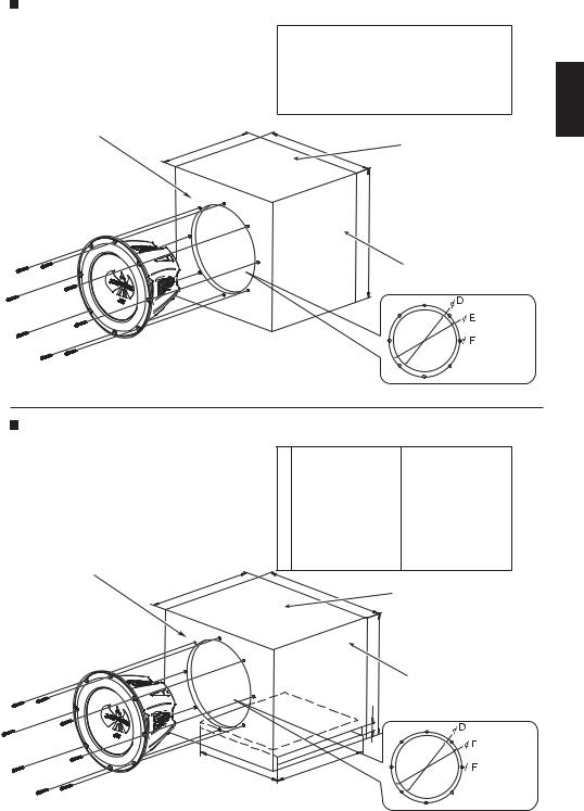
To install the sealed enclosure
When the speaker cannot be attached in the car, make the sealed enclosure as recommended in the table below—20 mm (3/4 inch) MDF is also
recommended for the enclosure materials. |
|
CS-AW7020 / CS-AW7040 |
|
CS-AW7220 / CS-AW7240 |
|
|
|
||||
|
|
|
|
||
|
A |
|
15-13/32 inch (391.7 mm) |
|
16-13/32 inch (417.1 mm) |
|
B |
|
15-13/32 inch (391.7 mm) |
|
16-13/32 inch (417.1 mm) |
|
C |
|
11-13/32 inch (290.1 mm) |
|
13-29/32 inch (353.6 mm) |
|
|
|
|
|
|
|
D |
|
9-4/32 inch (232 mm) |
|
10-14/32 inch (275.9 mm) |
|
|
|
|
|
|
|
E |
|
9-23/32 inch (247 mm) |
|
11-10/32 inch (295 mm) |
|
F |
|
4/32 inch (3 mm) |
|
4/32 inch (3 mm) |
|
G |
|
1.57 ft3 (0.045 m3) |
|
2.17 ft3 (0.062 m3) |
Front & Rear Baffle Boards (x 2)
C |
B |
Top & Bottom Sides (x 2) |
|
G : Internal Volume
A
Left & Right Sides (x 2)
ENGLISH
Mounting Hole Dimension
* Screw: Dia. 4mm x 50mm (x 8) (supplied)
To install the ported enclosure
When the speaker cannot be attached in the car, make the sealed enclosure as recommended in the table below—20 mm (3/4 inch) MDF is also recommended for the enclosure materials.
|
|
CS-AW7020 / CS-AW7040 |
CS-AW7220 / CS-AW7240 |
|
A |
15-13/32 inch (391.7 mm) |
15-13/32 inch (391.7 mm) |
|
B |
18-13/32 inch (467.9 mm) |
18-13/32 inch (467.9 mm) |
|
C |
13-13/32 inch (340.9 mm) |
15-13/32 inch (391.7 mm) |
|
|
|
|
|
D |
9-23/32 inch (247 mm) |
10-14/32 inch (275.9 mm) |
|
E |
9-23/32 inch (247 mm) |
11-10/32 inch (295 mm) |
|
F |
4/32 inch (3 mm) |
4/32 inch (3 mm) |
|
|
|
|
|
G |
1 inch (25.4 mm) |
1 inch (25.4 mm) |
|
|
|
|
|
H |
13 inch (330.2 mm) |
14 inch (355.6 mm) |
Front & Rear Baffle Boards (x 2) |
I |
13-19/32 inch (345.4 mm) |
13-6/32 inch (335.3 mm) |
|
|
|
|
J |
1.85 ft3 (0.052 m3) |
2.54 ft3 (0.072 m3) |
C |
B |
Top & Bottom Sides (x 2) |
|
||
|
|
|
|
|
J : Internal Volume |
|
A |
Left & Right Sides (x 2) |
|
G |
|
I H
Mounting Hole
Dimension
* Screw: Dia. 4mm x 50mm (x 8) (supplied) |
- 5- |
|
ENGLISH
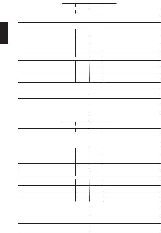
Parameters |
CS-AW7020 |
CS-AW7040 |
NOTES |
|||
parallel |
series |
parallel |
series |
|||
|
|
|||||
Nominal Impedance (Ω) |
2Ω + 2Ω |
4Ω + 4Ω |
|
|||
SPL (dB,1W/1M) |
83.49 dB |
83.54 dB |
84.02 dB |
84.12 dB |
SPL : Sound pressure level |
|
Displacement (Liter) |
|
0.123 ft3 |
|
|
||
Hole Cutout Diameter (inch) |
|
Dia. 9 - 6/32 inch |
|
|
||
(mm) |
|
( 233 mm ) |
|
|
||
Mounting Depth (inch) |
|
6 - 14/32 inch |
|
|
||
(mm) |
|
( 163.5 mm ) |
|
|
||
Re (Ω) |
0.98 Ω |
3.83 Ω |
1.92 Ω |
7.6 Ω |
Re : DC voice coil resistance |
|
BL (T.M) |
6.85 |
13.75 |
8.68 |
17.21 |
BL : Product of Flux density and |
|
Effective Voicecoil-wire length |
||||||
|
|
|
|
|
||
Vas (Liter) |
17.08 L |
16.98 L |
18.08 L |
18.28 L |
Vas : Volume of air equal to the driver |
|
compliance |
||||||
Vas (CuFt) |
|
|
|
|
||
0.6 ft3 |
0.599 ft3 |
0.64 ft3 |
0.65 ft3 |
|
||
Me (g) |
145.986 g |
147.109 g |
124.084 g |
122.443 g |
Me : Effective mass |
|
D (mm) |
|
Dia. 202 mm |
|
D : Effective cone diameter |
||
Fs (Hz) |
39.6 Hz |
39.5 Hz |
41.7 Hz |
41.8 Hz |
Fs : Driver free air resonance |
|
Qms |
10.261 |
10.282 |
9.021 |
9.169 |
Qms : Q of driver at Fs considering |
|
only non-electrical resistance |
||||||
|
|
|
|
|
||
Qes |
0.756 |
0.74 |
0.83 |
0.824 |
Qes : Q of driver at Fs considering |
|
only electrical resistance |
||||||
|
0.704 |
0.691 |
0.76 |
0.756 |
||
Qts |
Qts : Total Q of driver at Fs |
|||||
Pe [max.] (W) |
|
600 W |
|
Pe[max.] : Maximum continuous input |
||
|
|
power |
||||
|
|
|
|
|
||
Xmax.(mm) |
14.95 mm |
14.8 mm |
Xmax. : Maximum effective voicecoil |
|||
travel without distortion |
||||||
Freq.Responce (Hz) |
|
25 ~500 Hz |
|
|||
|
|
|
||||
Magnet Mass (oz) |
|
65.4 oz |
|
|
||
(g) |
|
( 1854.1 g ) |
|
|
||
Voice Coil(Aluminum)Dia.(inch) |
Dia. 2 - 5/32 inch |
Dia. 2 - 4/32 inch |
|
|||
(mm) |
54.5 mm |
53.59 mm |
|
|||
Hvc (mm) |
39.9 mm |
39.6 mm |
Hvc : Voice coil Height |
|||
Hag (mm) |
|
10 mm |
|
Hag : Gap Height |
||
|
|
|
|
|||
Parameters |
CS-AW7220 |
CS-AW7240 |
NOTES |
|||
parallel |
series |
parallel |
series |
|||
|
|
|||||
Nominal Impedance (Ω) |
2Ω + 2Ω |
4Ω + 4Ω |
|
|||
SPL (dB,1W/1M) |
85.13 dB |
85.2 dB |
85.87 dB |
85.65 dB |
SPL : Sound pressure level |
|
Displacement (Liter) |
|
0.18 ft3 |
|
|
||
Hole Cutout Diameter (inch) |
|
Dia. 10 - 29/32 inch |
|
|
||
(mm) |
|
( 277 mm ) |
|
|
||
Mounting Depth (inch) |
|
7 - 6/32 inch |
|
|
||
(mm) |
|
( 182.5 mm ) |
|
|
||
Re (Ω) |
0.98 Ω |
3.84 Ω |
1.94 Ω |
7.61 Ω |
Re : DC voice coil resistance |
|
BL (T.M) |
6.84 |
13.72 |
9.56 |
19.14 |
BL : Product of Flux density and |
|
Effective Voicecoil-wire length |
||||||
|
|
|
|
|
||
Vas (Liter) |
38.7 L |
38.76 L |
35.23 L |
35.05 L |
Vas : Volume of air equal to the driver |
|
compliance |
||||||
Vas (CuFt) |
|
|
|
|
||
1.37 ft3 |
1.37 ft3 |
1.24 ft3 |
1.24 ft3 |
|
||
Me (g) |
171.854 g |
172.934 g |
157.028 g |
157.336 g |
Me : Effective mass |
|
D (cm) |
|
Dia. 246 mm |
|
D : Effective cone diameter |
||
Fs (Hz) |
34.6 Hz |
34.5 Hz |
37.9 Hz |
38 Hz |
Fs : Driver free air resonance |
|
Qms |
10.277 |
10.089 |
8.931 |
9.014 |
Qms : Q of driver at Fs considering |
|
only non-electrical resistance |
||||||
|
|
|
|
|
||
Qes |
0.786 |
0.765 |
0.794 |
0.781 |
Qes : Q of driver at Fs considering |
|
only electrical resistance |
||||||
|
0.73 |
0.711 |
0.73 |
0.719 |
||
Qts |
Qts : Total Q of driver at Fs |
|||||
Pe [max.] (W) |
|
600 W |
|
Pe[max.] : Maximum continuous input |
||
|
|
power |
||||
|
|
|
|
|
||
Xmax.(mm) |
14.95 mm |
14.8 mm |
Xmax. : Maximum effective voicecoil |
|||
travel without distortion |
||||||
Freq.Responce (Hz) |
|
23 ~500 Hz |
|
|||
|
|
|
||||
Magnet Mass (oz) |
|
86.2 oz |
|
|
||
(g) |
|
( 2443.7 g ) |
|
|
||
Voice Coil(Aluminum)Dia.(inch) |
Dia. 2 - 5/32 inch |
Dia. 2 - 4/32 inch |
|
|||
(mm) |
( 54.5 mm ) |
( 53.59 mm ) |
|
|||
Hvc (mm) |
39.9 mm |
39.6 mm |
Hvc : Voice coil Height |
|||
Hag (mm) |
|
10 mm |
|
Hag : Gap Height |
||
 Loading...