


CA-VSDT9R
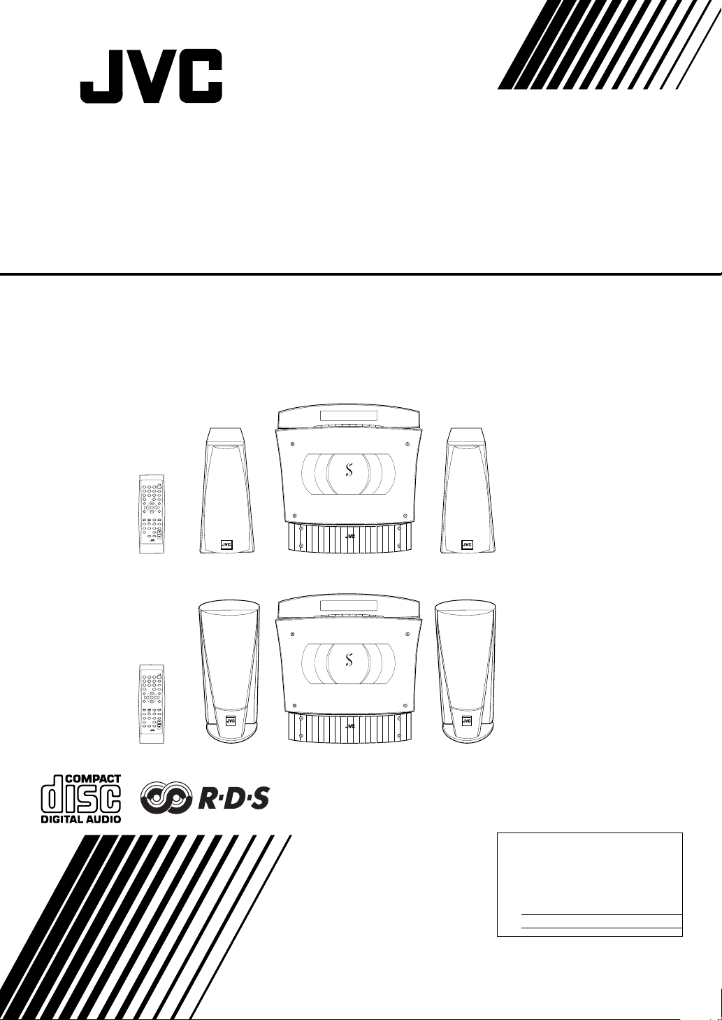
COMPACT COMPONENT SYSTEM
VS-DT6R/VS-DT7R/VS-DT9R
Consists of CA-VSDT6R and SP-VSDT6
Consists of CA-VSDT7R and SP-VSDT6
Consists of CA-VSDT9R and SP-VSDT9
123
4
7
10
MD/AUX
PTY
SEARCH
FM/AM
123
4
7
10
MD/AUX
PTY
SEARCH
FM/AM
COLOR
STANDBY/ON
PLAY MODE
6
5
REPEAT
9
8
FM MODE
10
+
TREBLEBASS
SET
CANCEL
PTY
TA/NEWS
SELECT
/INFO
DISPLAY
SLEEPDIMMER
MODE
DISPLAYAHB PRO
CLOCK
OPEN/
/TIMER
CLOSE
VOLUME
SP-VSDT6 SP-VSDT6
COMPACT COMPONENT SYSTEM
CA-VSDT6R
CA-VSDT7R
STANDBY/ON
PLAY MODE
6
5
REPEAT
9
8
FM MODE
10
+
TREBLEBASS
SET
CANCEL
PTY
TA/NEWS
SELECT
/INFO
DISPLAY
SLEEPDIMMER
MODE
DISPLAYAHB PRO
CLOCK
OPEN/
/TIMER
CLOSE
VOLUME
SP-VSDT9 SP-VSDT9
COMPACT COMPONENT SYSTEM
CA-VSDT9R
INSTRUCTIONS
For Customer Use:
Enter below the Model No. and Serial No.
which are located either on the rear, bottom or side of the cabinet. Retain this
information for future reference.
Model No.
Ser ial No.
LVT0853-009B
[B]
Warnings, Cautions and Others
CLASS 1
LASER PRODUCT
IMPORTANT
for the U.K.
DO NOT cut off the mains plug from this equipment. If the plug
fitted is not suitable for the power points in your home or the
cable is too short to reach a power point, then obtain an appropriate safety approved extension lead or consult your dealer.
BE SURE
to replace the fuse only with an identical approved
type, as originally fitted.
If nontheless the mains plug is cut off ensure to remove the fuse
and dispose of the plug immediately, to avoid a possible shock
hazard by inadvertent connection to the mains supply.
If this product is not supplied fitted with a mains plug then follow
the instructions given below:
IMPORTANT:
make any connection to the terminal which is marked
DO NOT
with the letter E or by the safety earth symbol or coloured green
or green-and-yellow.
The wires in the mains lead on this product are coloured in
accordance with the following code:
Blue :Neutral
Brown :Live
As these colours may not correspond with the coloured mark-
ings identifying the terminals in your plug proceed as follows:
The wire which is coloured blue must be connected to the terminal which is marked with the letter N or coloured black.
The wire which is coloured brown must be connected to the terminal which is marked with the letter L or coloured red.
IF IN DOUBT - CONSULT A COMPETENT ELECTRICIAN.
Caution —
%%%%
switch!
Disconnect the mains plug to shut the power off completely (the
%%%% goes off).
The %%%% switch in any position does not disconnect the mains
line.
•
When the unit is on standby, the %%%% lights red.
•
When the unit is turned on, the operation lamps light red.
The power can be remote controlled.
CAUTION
To reduce the risk of electrical shocks, fire, etc.:
1 Do not remove screws, covers or cabinet.
2 Do not expose this appliance to rain or moisture.
IMPORTANT FOR LASER PRODUCTS
REPRODUCTION OF LABELS
1 CLASSIFICATION LABEL, PLACED ON EXTERIOR SURFACE
2 WARNING LABEL, PLACED INSIDE THE UNIT
CAUTION: Invisible laser
radiation when open and
interlock failed or defeated.
AVOID DIRECT EXPOSURE
TO BEAM. (e)
1 CLASS 1 LASER PRODUCT
2
CAUTION:
lock failed or defeated. Avoid direct exposure to beam.
3
CAUTION:
serviceable parts inside the Unit; leave all servicing to qual-
ADVARSEL: Usynlig laserstråling ved åbning, når
sikkerhedsafbrydere er ude
af funktion. Undgåudsættelse for stråling. (d)
Invisible laser radiation when open and inter-
Do not open the top cover. There are no user
VARNING: Osynlig laserstrålning när denna del är
öppnad och spärren är
urkopplad. Betrakta ej
strålen. (s)
ified service personnel.
CAUTION
1. Do not block the ventilation openings or holes.
(If the ventilation openings or holes are blocked by a newspaper or cloth, etc., the heat may not be able to get out.)
2. Do not place any naked flame sources, such as lighted
candles, on the apparatus.
3. When discarding batteries, environmental problems must
be considered and local rules or laws governing the disposal of these batteries must be followed strictly.
4 Do not expose this apparatus to rain, moisture, dripping or
splashing and that no objects filled with liquids, such as
vases, shall be placed on the apparatus.
Caution: Proper Ventilation
To avoid risk of electric shock and fire, and to prevent damage,
locate the apparatus as follows:
1 Top: No obstructions and open spacing.
2 Sides/ Front/ Back: No obstructions should be placed in the
areas shown by the dimensions below.
3 Bottom: Place on the level surface. Maintain an adequate
air path for ventilation by placing on a stand with a height of
10 cm or more.
CAUTION
About the Internal Cooling Fan
■■■■
This unit includes an internal cooling fan, so as to allow for highpower operation within a small space.
This fan comes on when the sound level is set high, and may
also come on even at low sound levels if the internal temperature
rises. To ensure effective fan operation, please leave at least
1 cm clearance on each side of the unit.
VARO : Avattaessa ja
suojalukitus ohitettaessa
olet alttiina näkymättömälle lasersäteilylle.
Älä katso säteeseen. (f)
Front view
15 cm
G-1
15 cm
1 cm 1 cm
COMPACT COMPONENT SYSTEM
(Vertical position) (Horizontal position)
15 cm
10 cm
15 cm
15 cm
15 cm
1 cm 1 cm
COMPACT COMPONENT SYSTEM
10 cm

SAFETY INSTRUCTIONS
“SOME DOS AND DON’TS ON THE SAFE USE OF EQUIPMENT”
This equipment has been disigned and manufactured to meet international safety standards but, like any electrical
equipment, care must be taken if you are to obtain the best results and safety is to be assured.
✮✮✮✮✮✮✮✮✮✮✮✮✮✮✮✮ ✮✮✮✮✮✮✮✮✮✮✮✮✮✮✮✮ ✮✮✮✮✮✮✮✮✮✮✮✮✮✮✮
Do read the operating instructions before you attempt to use the equipment.
Do ensure that all electrical connections (including the mains plug, extension leads and interconnections between
pieces of equipment) are properly made and in accordance with the manufacturer’s instructions. Switch off and with-
draw the mains plug when making or changing connections.
Do consult your dealer if you are ever in doubt about the installation, operation or safety of your equipment.
Do be careful with glass panels or doors on equipment.
✮✮✮✮✮✮✮✮✮✮✮✮✮✮✮✮ ✮✮✮✮✮✮✮✮✮✮✮✮✮✮✮✮ ✮✮✮✮✮✮✮✮✮✮✮✮✮✮✮
DON’T continue to operate the equipment if you are in any doubt about it working normally, or if it is damaged in any
way–switch off, withdraw the mains plug and consult your dealer.
DON’T remove any fixed cover as this may expose dangerous voltages.
DON’T leave equipment switched on when it is unattended unless it is specifically stated that it is designed for unattended operation or has a standby mode.
Switch off using the switch on the equipment and make sure that your family know how to do this.
Special arrangements may need to be made for infirm or handicapped people.
DON’T use equipment such as personal stereos or radios so that you are distracted from the requirements of traffic
safety. It is illegal to watch television whilst driving.
DON’T listen to headphones at high volume as such use can permanently damage your hearing.
DON’T obstruct the ventilation of the equipment, for example with curtains or soft furnishings.
Overheating will cause damage and shorten the life of the equipment.
DON’T use makeshift stands and NEVER fix legs with wood screws — to ensure complete safety always fit the manufacturer’s approved stand or legs with the fixings provided according to the instructions.
DON’T allow electrical equipment to be exposed to rain or moisture.
ABOVE ALL
— NEVER let anyone, especially children, push anything into holes, slots or any other opening in the case -
this could result in a fatal electrical shock.;
— NEVER guess or take chances with electrical equipment of any kind
— it is better to be safe than sorry!
G-2

Introduction
Thank you for purchasing the JVC Compact Component System.
We hope it will be a valued addition to your home, giving you years of enjoyment.
Be sure to read this instruction manual carefully before operating your new stereo system.
In it you will find all the information you need to set up and use the system.
If you have a query that is not answered by the manual, please contact your dealer.
Features
Here are some of the things that make your System both powerful and simple to use.
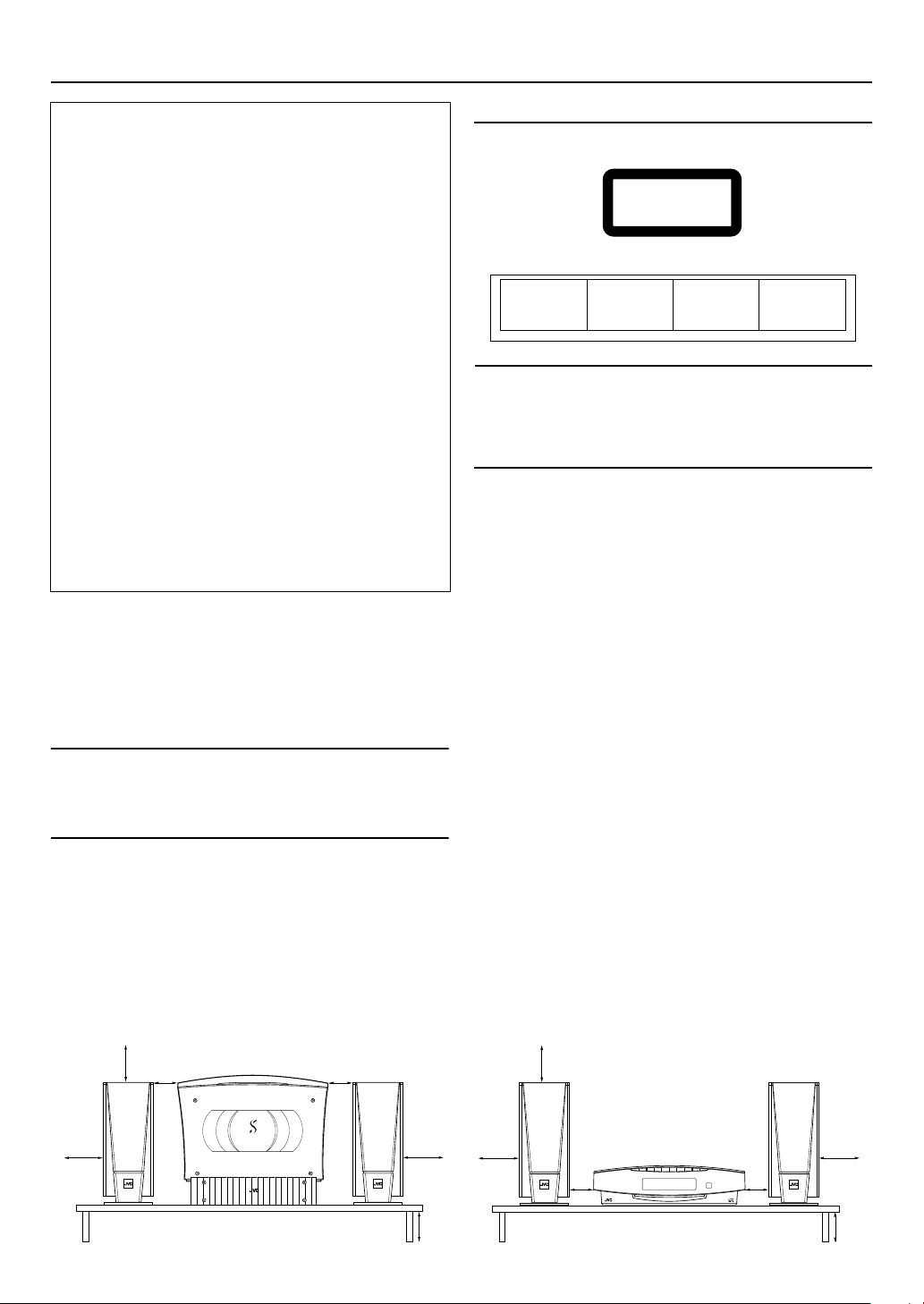
With the slot-loading CD mechanism, you can choose to place the System either vertically or horizontally.
■
The controls and operations have been redesigned to make them very easy to use, freeing you to
■
just enjoy the music.
• With JVC’s
CD Player with a single touch.
The System incorporates Active Hyper Bass PRO circuitry to faithfully reproduce low frequency sounds.
■
A 45-station preset capability (30 FM and 15 AM (MW/LW)) in addition to auto-seek and manual tuning.
■
CD options that include repeat, random and program play.
■
Timer functions; Daily Timer and Sleep Timer.
■
The System is compatible with RDS (Radio Data System) broadcasting.
■
• The Enahanced Other Networks data enables you to standby for desired information.
• The PTY Search function searches for programmes in the category you wish.
In addition, Radio Text can be displayed using data sent by station.
You can connect various external units, such as an MD recorder.
■
The system can play CD-R and CD-RW after they have been
■
You can play back your original CD-R or CD-RW recorded in Music CD format. (However they may not be played back
■
depending on their characteristics or recording conditions.)
COMPU PLAY
you can turn on the System and automatically start the Radio or
finalized
.
How This Manual Is Organized
• Basic information that is the same for many different functions - e.g. setting the volume - is given in the section
‘Basic Operations’, and not repeated under each function.
• The names of buttons/controls and display messages are written in all capital letters: e.g. FM/AM, “CD NO DISC”.
• System functions are written with an initial capital letter only: e.g. Normal Play.
Use the table of contents to look up specific information you require.
We have enjoyed making this manual for you, and hope it serves you in enjoying the many features built into your System.
WARNINGS
• DO NOT PUT ANYTHING ON THE PANEL. IF THE SYSTEM IS OPERATED WITH SOMETHING PUT
ON THE PANEL, IT WILL BE DAMAGED WHEN YOU TRY TO OPEN THE PANEL.
• SUPPLIED SPEAKERS ARE EXCLUSIVELY FOR THIS SYSTEM. USING WITH OTHER DEVICES WILL
DAMAGE THE SPEAKERS.
IMPORTANT CAUTIONS
Installation of the System
1
• Select a place which is level, dry and neither too hot nor too cold. (Between 5°C and 35°C or 41°F and 95°F.)
• Leave sufficient distance between the System and a TV.
• Do not use the System in a place subject to vibrations.
Power cord
2
• Do not handle the power cord with wet hands!
• Some power is always consumed as long as the power cord is connected to the wall outlet.
• When unplugging the System from the wall outlet, always pull the plug, not the power cord.
Malfunctions, etc.
3
• There are no user serviceable parts inside. In case of system failure, unplug the power cord and consult your dealer.
• Do not insert any metallic object into the System.
• Do not insert your hand between the Panel and the main body when the Panel is being closed.
1

Table of Contents
Introduction ........................................................................................................ 1
Features ......................................................................................................................................1
How This Manual Is Organized .................................................................................................1
WARNINGS ..............................................................................................................................1
IMPORTANT CAUTIONS .......................................................................................................1
Getting Started ................................................................................................... 3
Accessories.................................................................................................................................3
How To Put Batteries In the Remote Control ............................................................................3
Connecting the FM Antenna ......................................................................................................4
Connecting the AM (MW/LW) Antenna ...................................................................................5
Connecting the Speakers ............................................................................................................6
Connecting a Subwoofer ............................................................................................................7
Connecting External Equipment ................................................................................................7
Connecting an MD Recorder, etc (Digital Output)....................................................................8
Connecting the AC Power Cord.................................................................................................8
Installing the Unit on the Stand.................................................................................................. 8
Installing the Equipment on the Wall.........................................................................................9
Changing the Display and Control Buttons Settings................................................................ 10
Using the Remote Control........................................................................................................11
COMPU Play............................................................................................................................11
Basic Operations ............................................................................................. 12
Turning the Power On and Off.................................................................................................12
Adjusting the Brightness (DIMMER)......................................................................................12
Changing the Color (COLOR) (VS-DT9R only).....................................................................13
Adjusting the Volume ..............................................................................................................13
Reinforcing the Bass Sound (AHB PRO) ................................................................................14
Tone Control (BASS/TREBLE)...............................................................................................14
Showing the Time (DISPLAY)................................................................................................14
Using the Tuner................................................................................................15
Tuning In a Station................................................................................................................... 15
Presetting Stations....................................................................................................................16
To Change the FM Reception Mode........................................................................................17
Receiving FM Stations with RDS ............................................................................................17
Using the CD Player......................................................................................... 20
To Insert a CD.......................................................................................................................... 20
To Unload a CD ....................................................................................................................... 21
Basics of Using the CD Player — Normal Play.......................................................................21
Programming the Playing Order of the Tracks ........................................................................21
Random Play ............................................................................................................................ 22
Repeating Tracks......................................................................................................................22
Child Lock................................................................................................................................22
Using External Equipment .............................................................................. 23
Listening to External Equipment.............................................................................................. 23
Recording the System’s Source to External Equipment ..........................................................23
Using the Timers .............................................................................................. 24
Setting the Clock ...................................................................................................................... 24
Setting the Daily Timer............................................................................................................25
Setting the SLEEP Timer .........................................................................................................26
Care And Maintenance .................................................................................... 27
Troubleshooting............................................................................................... 28
Specifications....................................................................................Back cover
2
Getting Started
Accessories
Make sure that you have all of the following items, which are supplied with the System.
Power Cord (1)
AM Loop Antenna (1)
Remote Control (1)
Batteries (2)
FM Wire Antenna (1)
Speaker Cords (2)
Stand (1) (for Center Unit)
Legs (2) (for Stand)
Screw (1) (for Stand)
Paper Pattern (1)
If any of these items are missing, contact your dealer immediately.
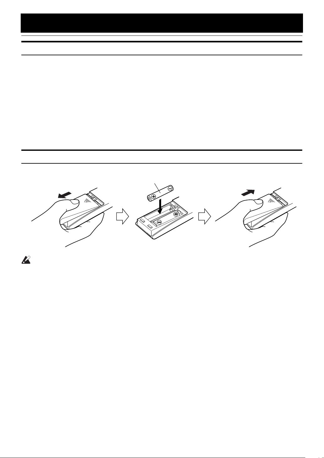
How To Put Batteries In the Remote Control
Match the polarity (+ and –) on the batteries with the + and – markings in the battery compartment.
R6P(SUM-3)/AA(15F)
CAUTION:
• Handle batteries properly.
To avoid battery leakage or explosion:
■
• Remove batteries when the Remote Control will not be used for a long time.
• When you need to replace the batteries, replace both batteries at the same time with new ones.
• Do not use an old battery with a new one.
• Do not use different types of batteries together.
3
CAUTION:
• Make all connections before plugging the System into an AC power outlet.
(Only if you install the Center Unit vertically)
• To place the Center Unit
vertically
attached. (See page 8.) To make connections, let the cords pass in
the holes of the Stand as shown in the diagram before attaching the
Stand and Legs.
, the Stand and Legs must be
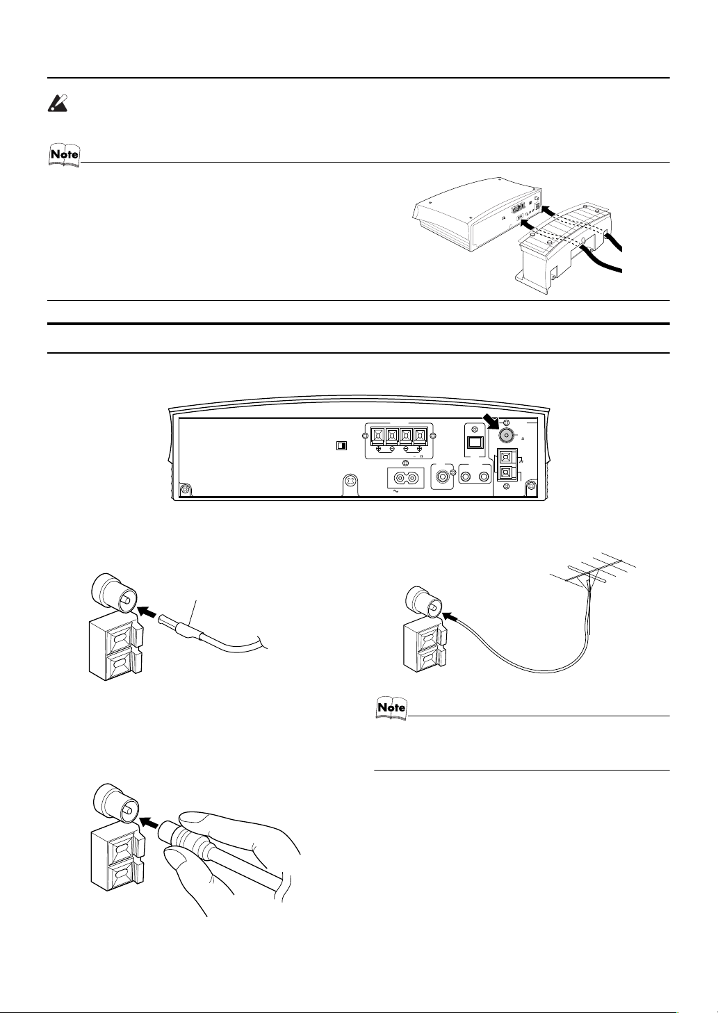
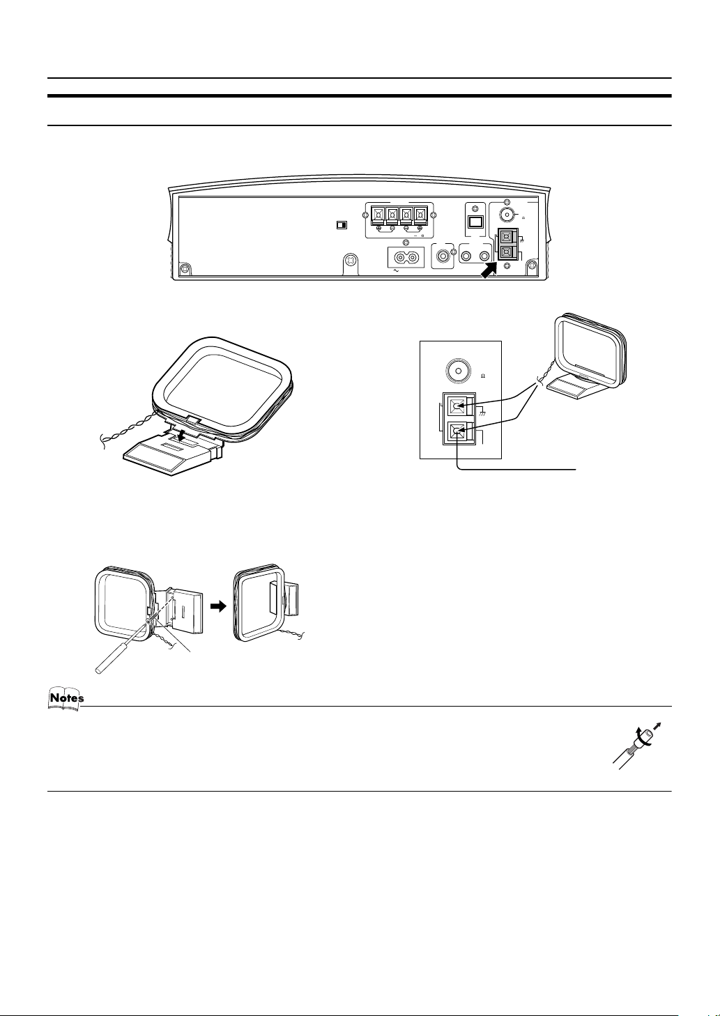
Connecting the FM Antenna
Rear Panel of the Center Unit
Getting Started
Using the Supplied Wire Antenna
FM wire antenna (supplied)
Using the Coaxial Type Connector
(Not Supplied)
A 75 Ω antenna with coaxial type connector (IEC or DIN45
325) should be connected to the FM 75 Ω COAXIAL terminal.
H
DISP.SET
V
SPEAKERS
R
SPEAKER IMPEDANCE 4 16
AC IN
L
SUB
WOOFER
CD DIGITAL
MD/AUX
OUT IN
ANTENNA
FM
(
)
75
COAXIAL
AM
LOOP
OUT
AM
EXT
If reception is poor, connect the outdoor antenna.
Coaxial cable
• Before attaching a 75 Ω coaxial lead (the kind with a
round wire going to an outdoor antenna), disconnect the
supplied FM Wire Antenna.
FM outdoor
antenna
(Not supplied)
4
Getting Started
Connecting the AM (MW/LW) Antenna
Rear Panel of the Center Unit
H
V
DISP.SET
AM loop antenna (Supplied)
Attach the AM loop to its base by snapping the tabs on
the loop into the slot in the base.
• The AM loop antenna can be attached to a wall.
SPEAKERS
R
SPEAKER IMPEDANCE 4 16
AC IN
ANTENNA
FM
(
)
75
75
COAXIAL
AM
LOOP
AM
EXT
FM
)
AM
EXT
Outdoor single vinylcovered wire
(not supplied)
L
AM
LOOP
SUB
WOOFER
CD DIGITAL
OUT
MD/AUX
OUT IN
ANTENNA
(
COAXIAL
Turn the loop until you have the best reception.
Screw (not supplied)
• If the AM loop antenna wire is covered with vinyl, remove the vinyl by twisting it as shown in the diagram.
• Make sure the antenna conductors do not touch any other terminals, connecting cords and power cord.
This could cause poor reception.
• If reception is poor, connect an outdoor single vinyl-covered wire to the AM EXT terminal. (Keep the AM loop
antenna connected.)
5
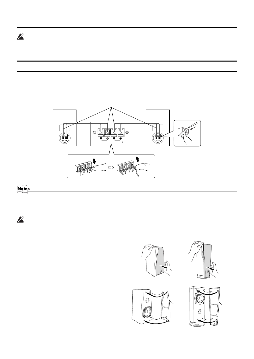
Getting Started
CAUTION:
• Make all connections before plugging the System into an AC power outlet.
• Handling the speakers
As this is a precision instrument, handle it carefully so as to protect it from shocks.
Connecting the Speakers
These speakers are exclusively for this system. Using with other devices will damege the speakers.
1. Open each of the terminals to connect the speaker wire leads.
2. Connect the speaker cords between the Speaker terminals of the Unit and the terminals of the Speakers.
Connect the cords with a black line to the (–) terminals and cords without a black line to the (+) terminals.
3. Close each of the terminals to securely connect the cords.
Right side (rear view) Left side (rear view)Marked with a black line
SPEAKERS
L
R
SPEAKER IMPEDANCE 4 16
• Since both speakers are the same, you can put either one to the right or left side.
• Do not connect other speakers to the Unit. The difference of the load impedance causes failures.
• Do not use the supplied speakers in parallel with other speakers.
CAUTION:
• Although the speaker SP-VSDT9 has internal magnetic shielding, a TV may display irregular
colors if located near the speakers. If this happens, set the speakers away from the TV.
Removing the speaker grilles
The speaker grilles can be removed.
(SP-VSDT6)
(SP-VSDT9)
When removing:
1. Pull the bottom towards you with your fingers.
2. Also pull the top towords you.
When attaching the speaker grilles:
Attach the speaker grilles as shown in the diagram.
(SP-VSDT6)
Speaker
grille
(SP-VSDT9)
Speaker
grille
6
Getting Started
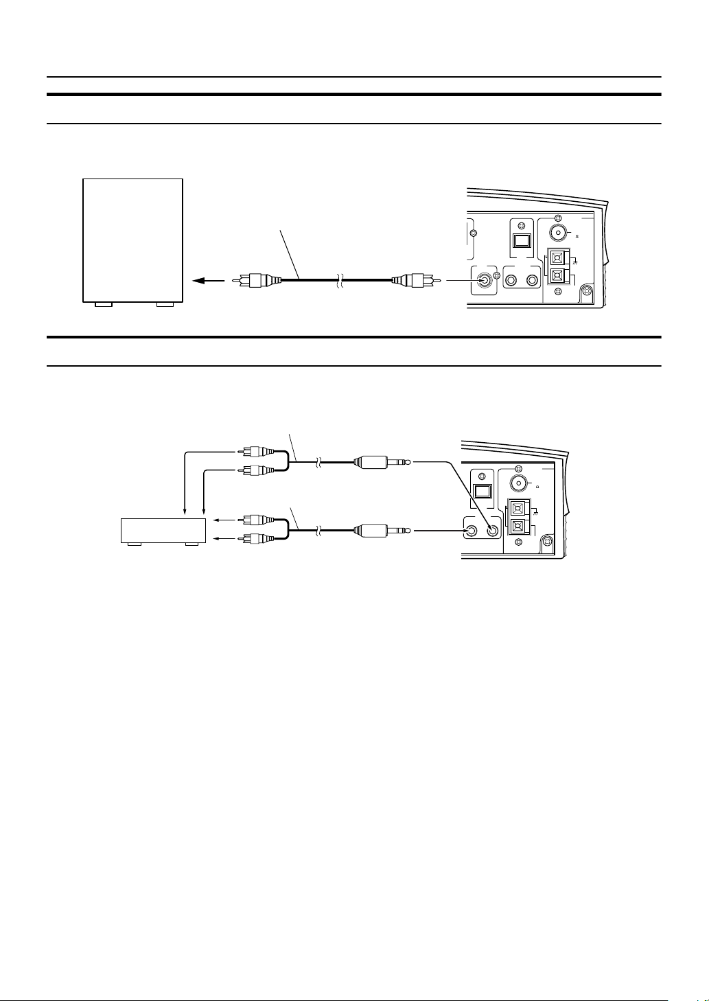
Connecting a Subwoofer
Connect a signal cord (not supplied) between the System’s SUBWOOFER terminal and the input terminal of an external subwoofer.
Subwoofer (not suipplied)
LOOP
ANTENNA
FM
(
)
75
COAXIAL
AM
AM
EXT
Signal cord (not supplied)
SUB
WOOFER
CD DIGITAL
OUT
MD/AUX
OUT IN
Connecting External Equipment
Connect signal cords (not supplied) between the System’s MD/AUX-OUT/IN terminals and the output/input terminals of the
external MD recorder, tape deck, etc.
You can then listen to the external source through the System or record the System’s CD player or tuner to the external unit.
Signal cord (not supplied)
MD recorder or tape deck
(not supplied)
Pin-plug x 2
Signal cord (not supplied)
Pin-plug x 2
Stereo mini-plug
Stereo mini-plug
CD DIGITAL
OUT
MD/AUX
OUT IN
LOOP
ANTENNA
FM
(
)
75
COAXIAL
AM
AM
EXT
7
 Loading...