


 Loading...
Color Television Users Guide
For Models:
AV-32S776
AV-32S766
AV-30W776
AV-27S776
TV CATV VCR DVD |
POWER |
||||
|
|
|
|
|
INPUT |
SLEEP |
|
|
|
|
|
TIMER |
DISPLAY |
C.C. |
|
D/A |
|
THEATER PRO |
1 |
|
2 |
3 |
|
|
|
|
|||
VIDEO STATUS |
4 |
|
5 |
6 |
|
|
|
|
|||
ASPECT |
|
7 |
|
8 |
9 |
|
|
|
|||
SUB CH |
|
TUNE |
0 |
RETURN+ |
|
|
|
|
|
/TV |
|
FAVORITE ML/MTS |
SOUND |
GUIDE |
|||
MUTING |
|
|
|
|
OK |
|
|
CH + |
|
|
|
VOL |
|
|
|
|
VOL |
–+
CH –
MENU |
BACK |
VCR CHANNEL |
VCR/DVD |
PREV NEXT |
POWER TV/VCR |
REW PLAY FF
REC |
STOP |
PAUSE |
 OPEN/CLOSE STILL/PAUSE
RM-C1270G
TV
Illustration of AV-30W776 and RM-C1270G
Important Note:
In the spaces below, enter the model and serial number of your television (located at the rear of the television cabinet). Staple your sales receipt or invoice to the inside cover of this guide. Keep this user’s guide in a convenient place for future reference. Keep the carton and original packaging for future use.
Model Number:
Serial Number:
LCT1855-001A-A 0705JGI-II-IM
Important Safety Precautions
CAUTION
RISK OF ELECTRIC SHOCK
DO NOT OPEN
CAUTION: To reduce the risk of electric shock. Do not remove cover (or back). No user serviceable parts inside. Refer servicing to qualified service personnel.
The lightning flash with arrowhead symbol, within an equilateral triangle is intended to alert the user to the presence of uninsulated “dangerous voltage” within the product’s enclosure that may be of sufficient magnitude to constitute a risk of electric shock to persons.
The exclamation point within an equilateral triangle is intended to alert the user to the presence of important operating and maintenance (servicing) instructions in the literature accompanying the appliance.
WARNING: TO PREVENT FIRE OR SHOCK HAZARDS, DO NOT EXPOSE THIS TV
SET TO RAIN OR MOISTURE.
CAUTION: TO INSURE PERSONAL SAFETY, OBSERVE THE FOLLOWING RULES
REGARDING THE USE OF THIS UNIT.
1.Operate only from the power source specified on the unit.
2.Avoid damaging the AC plug and power cord.
3.Avoid Improper installation and never position the unit where good ventilation is unattainable.
4.Do not allow objects or liquid into the cabinet openings.
5.In the event of trouble, unplug the unit and call a service technician. Do not attempt to repair it yourself or remove the rear cover.
Changes or modifications not approved by JVC could void the warranty.
*When you don’t use this TV set for a long period of time, be sure to disconnect both the power plug from the AC outlet and antenna for your safety.
*To prevent electric shock do not use this polarized plug with an extension cord, receptacle or other outlet unless the blades can be fully inserted to prevent blade exposure.
IMPORTANT RECYCLING INFORMATION
This product utilizes both a Cathode Ray Tube (CRT) and other components that contain lead. Disposal of these materials may be regulated in your community due to environmental considerations. For disposal or recycling information, please contact your local authorities, or the Electronic Industries Alliance: http://www.eiae.org
2
•As an “ENERGY STAR®” partner,
JVC has determined that this product or product model meets the
“ENERGY STAR®” guidelines for energy efficiency.
Important Safeguards
CAUTION:
Please read and retain for your safety.
Electrical energy can perform many useful functions. This TV set has been engineered and manufactured to assure your personal safety. But improper use can result in potential electrical shock or fire hazards. In order not to defeat the safeguards incorporated in this TV set, observe the following basic rules for its installation, use and servicing. Also follow all
warnings and instructions marked on your TV set.
INSTALLATION |
(POLARIZED-TYPE) |
|
1 Your TV set is equipped with a polarized AC line plug (one |
||
|
||
blade of the plug is wider than the other). This safety feature |
|
|
allows the plug to fit into the power outlet only one way. |
|
|
Should you be unable to insert the plug fully into the outlet, |
|
|
try reversing the plug. Should it still fail to fit, contact your |
|
|
electrician. |
|
2Operate the TV set only from a power source as indicated on the TV set or refer to the operating instructions for this information. If you are not sure of the type of power supply to your home, consult your TV set dealer or local power company. For battery operation, refer to the operating instructions.
3Overloaded AC outlets and extension cords are dangerous, and so are frayed power cords and broken plugs. They may result in a shock or fire hazard. Call your service technician for replacement.
4Do not allow anything to rest on or roll over the power cord, and do not place the TV set where power cord is subject to traffic or abuse. This may result in a shock or fire hazard.
5Do not use this TV set near water — for example, near a bathtub, washbowl, kitchen sink, or laundry tub, in a wet basement, or near swimming pool, etc.
6If an outside antenna is connected to the TV set, be sure the antenna system is grounded so as to provide some protection against voltage surges and built-up static charges.
Section 810 of the National Electrical Code provides information with respect to proper grounding of the mast and supporting structure, grounding of the lead-in wire to an antenna discharge unit, size of grounding conductors, location of antenna discharge unit, connection requirements for the grounding electrode.
3
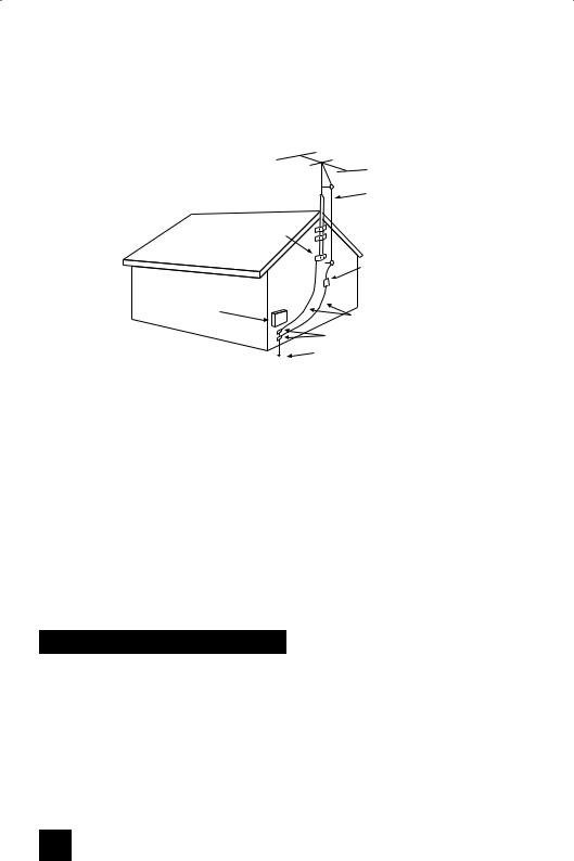
7An outside antenna system should not be located in the vicinity of overhead power lines or other electric light or power circuits, or where it can fall into such power lines or circuits. When installing an outside antenna system, extreme care should be taken to keep from touching such power lines or circuits as contact with them might be fatal.
EXAMPLE OF ANTENNA GROUNDING
AS PER NATIONAL ELECTRICAL CODE
|
ANTENNA |
|
|
LEAD IN |
|
|
WIRE |
|
|
GROUND |
|
|
CLAMP |
|
|
ANTENNA |
|
|
DISCHARGE UNIT |
|
|
(NEC SECTION 810-20) |
|
ELECTRICAL |
|
|
SERVICE |
GROUNDING CONDUCTORS |
|
EQUIPMENT |
||
(NEC SECTION 810-21) |
||
|
||
|
GROUND CLAMPS |
|
|
POWER SERVICE GROUNDING |
|
|
ELECTRODE SYSTEM |
|
NEC - NATIONAL ELECTRIC CODE |
(NEC ARTICLE 250, PART H) |
|
|
8TV sets are provided with ventilation openings in the cabinet to allow heat generated during operation to be released.
Therefore:
—Never block the bottom ventilation slots of a portable TV set by placing it on a bed, sofa, rug, etc.
—Never place a TV set in a “built-in” enclosure unless proper ventilation is provided.
—Never cover the openings with a cloth or other material.
—Never place the TV set near or over a radiator or heat register.
9To avoid personal injury:
—Do not place a TV set on a sloping shelf unless properly secured.
—Use only a cart or stand recommended by the TV set manufacturer.
—Do not try to roll a cart with small casters across thresholds or deep pile carpets.
—Wall or shelf mounting should follow the manufacturer’s instructions, and should use a mounting kit approved by the manufacturer.
Use
10Caution children about dropping or pushing objects into the TV set through cabinet openings. Some internal parts carry hazardous voltages and contact can result in a fire or electrical shock.
11Unplug the TV set from the wall outlet before cleaning. Do not use liquid or an aerosol cleaner.
12Never add accessories to a TV set that has not been designed for this purpose. Such additions may result in a hazard.
4

PORTABLE CART WARNING (Symbol provided by RETAC)
13For added protection of the TV set during a lightning storm or when the TV set is to be left unattended for an extended period of time, unplug it from the wall outlet and disconnect the antenna. This will prevent damage to product due to lightning storms or power line surges.
14A TV set and cart combination should be moved with care. Quick stops, excessive force, and uneven surfaces may cause the TV set and cart combination to overturn.
Service
15Unplug this TV set from the wall outlet and refer servicing to qualified service personnel under the following conditions:
A.When the power cord or plug is damaged or frayed.
B.If liquid has been spilled into the TV set.
C.If the TV set has been exposed to rain or water.
D.If the TV set does not operate normally by following the operating instructions. Adjust only those controls that are covered in the operating instructions as improper adjustment of other controls may result in damage and will often require extensive work by a qualified technician to restore the TV set to normal operation.
E.If the TV set has been dropped or damaged in any way.
F.When the TV set exhibits a distinct change in performance — this indicates a need for service.
16Do not attempt to service this TV set yourself as opening or removing covers may expose you to dangerous voltage or other hazards. Refer all servicing to qualified service personnel.
17When replacement parts are required, have the service technician verify in writing that the replacement parts he uses have the same safety characteristics as the original parts. Use of manufacturer’s specified replacement parts can prevent fire, shock, or other hazards.
18Upon completion of any service or repairs to this TV set, please ask the service technician to perform the safety check described in the manufacturer’s service literature.
19When a TV set reaches the end of its useful life, improper disposal could result in a picture tube implosion. Ask a qualified service technician to dispose of the TV set.
20Note to CATV system installer.
This reminder is provided to call the CATV system installer’s attention to Article 820-40 of the NEC that provides guidelines for proper grounding and, in particular, specifies that the cable ground shall be connected to the grounding system of the building, as close to the point of cable entry as practical.
5

Table of Contents
Quick Setup . . . . . . . . . . . 8
Unpacking your TV . . . . . . . . . . . . 8
TV Models . . . . . . . . . . . . . . . . 9
TV Remote Control . . . . . . . . . . . 11 Getting Started . . . . . . . . . . . . . 12 The Remote Control . . . . . . . . . . 12
Connecting Your Devices . . . . . . . 13
Interactive Plug In Menu . . . . . . . . 20
Remote Programming . . . . . 23
Setting CATV, VCR and DVD Codes . . . 23
CATV or Satellite Codes . . . . . . . . 23 VCR Codes . . . . . . . . . . . . . . 24
DVD Codes . . . . . . . . . . . . . . 25 Search Codes . . . . . . . . . . . . . 26
Onscreen Menus . . . . . . . . 27
Using the Guide . . . . . . . . . . . . . 27 Onscreen Menu System . . . . . . . . . 28
Initial Setup . . . . . . . . . . 30
Auto Tuner Setup . . . . . . . . . . . . 30 Channel Summary . . . . . . . . . . . . 30 V-Chip . . . . . . . . . . . . . . . . . . 32 Set Lock Code . . . . . . . . . . . . . 38 Language . . . . . . . . . . . . . . . . 39
Closed Caption . . . . . . . . . . . . . 40
Auto Shut Off . . . . . . . . . . . . . . 42
XDS ID . . . . . . . . . . . . . . . . . 42
Tilt Correction . . . . . . . . . . . . . . 42 Noise Muting . . . . . . . . . . . . . . 43 Front Panel Lock . . . . . . . . . . . . 43 V1 Smart Input . . . . . . . . . . . . 44 Video Input Label . . . . . . . . . . . . . 44 Position Adjustment . . . . . . . . . . . . 45 Digital-In . . . . . . . . . . . . . . . . . 46
Digital-In Audio . . . . . . . . . . . . . 46
Picture Adjust . . . . . . . . . 47
Picture Settings . . . . . . . . . . . . . 47 Adjust Picture Settings . . . . . . . . . 47 Color Temperature . . . . . . . . . . . . 47 Digital Noise Clear . . . . . . . . . . . . 47
Natural Cinema . . . . . . . . . . . . . 48
VSM . . . . . . . . . . . . . . . . . . . 48 Reset . . . . . . . . . . . . . . . . . . 48
Sound Adjust . . . . . . . . . 49
Sound Settings . . . . . . . . . . . . . 49
Adjust Sound Settings . . . . . . . . . 49
Reset . . . . . . . . . . . . . . . . . . 49
Clock Timers . . . . . . . . . . 50
Set Clock . . . . . . . . . . . . . . |
. . 50 |
On/Off Timer . . . . . . . . . . . . . |
. . 51 |
Button Functions . . . . . . . 52 |
|
Power . . . . . . . . . . . . . . . . |
. . 52 |
Number Buttons . . . . . . . . . . . |
. . 52 |
Tune . . . . . . . . . . . . . . . . |
. . 52 |
Input . . . . . . . . . . . . . . . . . |
. . 52 |
Channel +/- . . . . . . . . . . . . . . 52 |
|
Volume +/- . . . . . . . . . . . . . . |
. 52 |
Return+/TV . . . . . . . . . . . . . . |
. 53 |
Sound . . . . . . . . . . . . . . . . . |
. 53 |
Muting . . . . . . . . . . . . . . . . . |
. 53 |
Video Status . . . . . . . . . . . . . . |
. 54 |
TheaterPro D6500K . . . . . . . . . . |
. 54 |
Sleep Timer . . . . . . . . . . . . . . |
. 54 |
Display . . . . . . . . . . . . . . . . |
. 55 |
C.C. . . . . . . . . . . . . . . . . . . |
. 55 |
Aspect . . . . . . . . . . . . . . . . |
. 56 |
Aspect Ratios . . . . . . . . . . . . |
. 56 |
Favorite . . . . . . . . . . . . . . . . . . |
. 59 |
ML/MTS . . . . . . . . . . . . . . . . . . |
. 60 |
Menu . . . . . . . . . . . . . . . . . |
. 60 |
OK . . . . . . . . . . . . . . . . . . |
. 60 |
Back . . . . . . . . . . . . . . . . . . |
. 60 |
TV/CATV Slide Switch . . . . . . . . . |
. 61 |
VCR/DVD Slide Switch . . . . . . . |
. . 61 |
VCR Buttons . . . . . . . . . . . . . . |
. 61 |
DVD Buttons . . . . . . . . . . . . . . |
. 61 |
6

Table of Contents
Digital Setup . . . . . . . . . 62
Digital Setup . . . . . . . . . . . . . 62
Antenna Level . . . . . . . . . . . . . 62
Digital Sound . . . . . . . . . . . . . 63
Software Update . . . . . . . . . . . . 64
Software Version . . . . . . . . . . . 64
Digital Button Functions . . . 65
Digital CH D/A (Digital/Analog) . . . . . 65
Sub Channel . . . . . . . . . . . . . 65
Guide . . . . . . . . . . . . . . . 66
OSD Information . . . . . . . . 67
Weak Signal . . . . . . . . . . . . . 67
No Program . . . . . . . . . . . . . . 67
Appendices . . . . . . . . . . 68
Troubleshooting . . . . . . . . . . . . . 68
Warranty . . . . . . . . . . . . . . 69
Authorized Service Centers . . . . . . . 70
Specifications . . . . . . . . . . . . . 71
Notes . . . . . . . . . . . . . . . . . 75
7
Quick Setup |
Unpacking your TV |
|
|
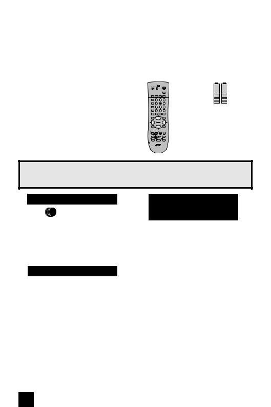
Thank you for your purchase of a JVC Color Television. Before you begin setting up your new television, please check to make sure you have all of the following items. In addition to this guide, your television box should include:
1 Television |
1 Remote Control |
|||||
|
TV CATV VCR DVD |
POWER |
||||
|
|
|
|
|
|
INPUT |
|
SLEEP |
|
|
|
|
|
|
TIMER |
DISPLAY |
C.C. |
D/A |
||
|
THEATER PRO |
1 |
|
2 |
3 |
|
|
|
|
|
|||
|
VIDEO STATUS |
4 |
|
5 |
6 |
|
|
|
|
|
|||
|
ASPECT |
|
7 |
|
8 |
9 |
|
|
|
|
|||
|
SUB CH |
|
TUNE |
0 |
RETURN+ |
|
|
|
|
|
|
/TV |
|
|
FAVORITE ML/MTS |
SOUND |
GUIDE |
|||
|
MUTING |
|
|
|
|
OK |
|
|
|
CH + |
|
|
|
|
VOL |
|
|
|
|
VOL |
|
– |
|
|
|
|
+ |
|
|
|
CH – |
|
|
|
|
MENU |
|
|
|
|
BACK |
|
VCR CHANNEL |
VCR/DVD |
|
|||
|
PREV NEXT |
POWER TV/VCR |
||||
|
REW |
|
PLAY |
|
FF |
|
|
REC |
|
STOP |
|
PAUSE |
|
|
OPEN/CLOSE |
|
|
STILL/PAUSE |
||
RM-C1270G
TV
Two AA
Batteries
Alkaline AA |
Alkaline AA |
Note: Your television and/or remote control may differ from the examples illustrated here.
Once you have unpacked your television, the next step is to connect it to your antenna/ cable or satellite system and to connect the audio/video devices you want to use with your television. To make these connections you will use plugs like the ones illustrated below.
Coaxial Cables
Used to connect an external antenna or cable TV system to your TV.
S-Video Cable
Used to make video connections with S-Video
VCRs, Camcorders and
DVD players.
Component Cables
Composite Cables
Audio Cables
Used to connect audio/ video devices like
VCRs, DVD players, stereo amplifiers, game consoles, etc.
We recommend that before you start using your new television, you read your entire User’s Guide so you can learn about your new television’s many great features. If you’re anxious to start using your television right away, a quick setup guide follows on the next few pages.
8
Quick Setup |
TV Models |
|
|
NOTE: Before you connect your television to another device, please refer to the proper diagrams for your specific TV and remote. These will help assist you in understanding how to connect your television to another device, as well as use the remote to set up your television.
Rear Panel Diagram
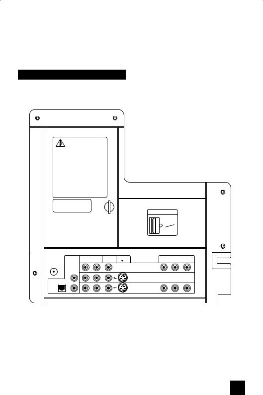
MODELS : AV-32S776, AV-32S766, AV-30W776, AV-27S776
UNPLUG THE POWER CORD FROM
AC OUTLET BEFORE REMOVING THE
REAR COVER
When the rear cover is removed, follow "CAUTION AT DISASSEMBLY" procedure in the service manual before plugging the TV's power cord into an AC outlet. Failure to follow the procedure will result in PERMANENT damage to some of the television features.
DÉBRANCHEZ LE CORDON DE LA PRISE DE COURANT C.A. AVANT DE RETIRER LE COUVERCLE ARRIÈRE.
Une fois le couvercle arrière déposé suivez la procédure ««ATTENTION LORS DU DÉMONTAGE»» décrite dans la manuel de service avant de brancher le cordon du téléviseur dans une prise c.a. L'omission de suivre la procédure causera des dommages PERMANENTS à certaines fonctions du téléviseur.
Manufactured under license from Dolby Laboratories. "Dolby" and the double-D symbol are trademarks of Dolby Laboratories.
SERVICE
ONLY
Note: The terminal labeled "SERVICE ONLY", is exclusively used to update the software version.
DIGITAL-IN
VIDEO (DIGITAL)
AUDIO (DIGITAL)
|
AUDIO |
|
AUDIO |
VIDEO |
S-VIDEO |
COMPONENT VIDEO |
|
75Ω |
OUT |
R |
L |
|
Y |
Pb |
Pr |
|
|
|
|
|
|
|
|
(VHF/UHF) |
|
|
|
|
INPUT-3 |
|
|
|
R |
|
|
|
INPUT-2 |
|
|
|
|
|
|
|
|
|
|
OPTICAL OUT |
|
|
|
|
OVER |
|
|
|
|
|
|
|
|
|
|
Digital |
L |
|
|
|
|
|
|
|
|
|
|
INPUT-1 |
|
|
|
Audio |
|
|
|
|
|
|
|
|
|
|
|
OVER |
|
|
|
9
Quick Setup |
TV Models |
|
|
NOTE: Before you connect your television to another device, please refer to the proper diagrams for your specific TV and remote. These will help assist you in understanding how to connect your television to another device, as well as use the remote to set up your television.
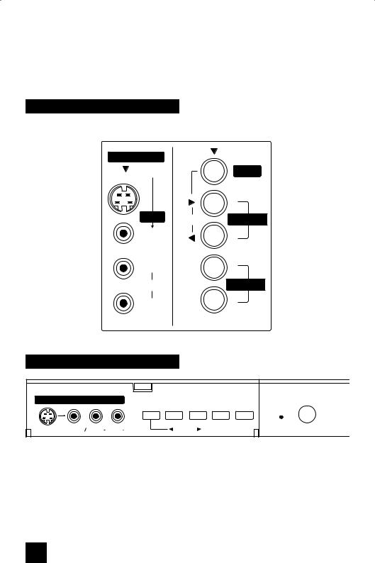
Side panel diagram
MODEL: AV-30W776
INPUT 4
S-VIDEO |
MENU |
|
|
|
+ |
OVER |
OPERATE |
CHANNEL |
|
||
VIDEO |
|
– |
|
|
|
L/MONO |
|
+ |
AUDIO |
|
VOLUME |
R |
|
– |
Front panel diagram
|
INPUT 4 |
|
MENU |
- CHANNEL + |
- VOLUME+ |
ON TIMER |
POWER |
|
|
OVER |
|
|
|
|
|
|
|
S-VIDEO |
VIDEO L |
MONO |
AUDIO R |
|
OPERATE |
|
|
|
MODELS: AV-32S776, AV-32S766, AV-27S776
10
Quick Setup |
TV Remote Control |
|
|
TV CATV VCR DVD |
POWER |
||||
|
|
|
|
|
INPUT |
SLEEP |
|
|
|
|
|
TIMER |
DISPLAY |
C.C. |
|
D/A |
|
THEATER PRO |
1 |
|
2 |
3 |
|
|
|
|
|||
VIDEO STATUS |
4 |
|
5 |
6 |
|
|
|
|
|||
ASPECT |
|
7 |
|
8 |
9 |
|
|
|
|||
SUB CH |
|
TUNE |
0 |
RETURN+ |
|
|
|
|
|
/TV |
|
FAVORITE ML/MTS |
SOUND |
GUIDE |
|||
MUTING |
|
|
|
|
OK |
|
|
CH + |
|
|
|
VOL |
|
|
|
|
VOL |
–+
CH –
MENU |
BACK |
VCR CHANNEL |
VCR/DVD |
PREV NEXT |
POWER TV/VCR |
REW PLAY FF
REC |
STOP |
PAUSE |
 OPEN/CLOSE STILL/PAUSE
RM-C1270G
TV
RM-C1270G
MODELS:
AV-32S776
AV-32S766
AV-30W776
AV-27S776
•For information on remote control buttons, see pages 52 - 61 and 65 - 66.
•SUB CHANNEL and GUIDE buttons are for digital channels. If your TV is connected to an ATSC antenna or Digital Cable, you can use these buttons.
11
Quick Setup |
Getting Started |
|
|
Getting Started
These quick setup pages will provide you, in three easy steps, with the basic information you need to begin using your new television right away.
If you have questions, or for more detailed information on any of these steps, please consult other sections of this manual.
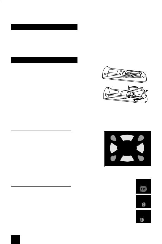
Step 1 – The Remote Control
Before you can operate your remote control, you first need to install the batteries (included).
Lift and pull the latch on the back of the remote control to open. Insert two batteries (included) carefully noting the “+” and “–” markings, placing the “–” end in the unit first. Snap the cover back into place.
When you change the batteries, try to complete the task within three minutes. If you take longer than three minutes, the remote control codes for your VCR, DVD, and/or cable box/satellite receiver may have to be reset. See pages 23 - 26.
Key Feature Buttons
The four key feature buttons at the center of the remote can be used for basic operation of the television. The top and bottom buttons will scan forward and back through the available channels. To move rapidly through the channels using JVC’s Hyperscan feature, press and hold CH+ or
CH–. The channels will zip by at a rate of five channels per second. The right and left buttons will turn the volume up or down. These buttons are also marked with four arrows and are used with JVC’s onscreen menu system. To use the onscreen menus, press the MENU button.
MUTING |
OK |
|
CH + |
VOL |
VOL |
–+
CH –
MENU |
BACK |
Basic Operation
Turn the television on and off by pressing the POWER button at the top right corner of the remote. If this is the first time you are turning on the TV, the interactive plug-in menu appears.
•Make sure the TV/CATV switch is set to TV. Move the switch to CATV only if you need to operate a cable box.
•Slide the VCR/DVD selector switch to VCR to control a VCR. Slide to
DVD to control a DVD player. Please see pages 23 to 26 for instructions on programming your remote control to operate a cable box, VCR or DVD player.
POWER
TV CATV
VCR DVD
12
Quick Setup |
Connections |
|
|
Step 2 – Connecting Your Devices
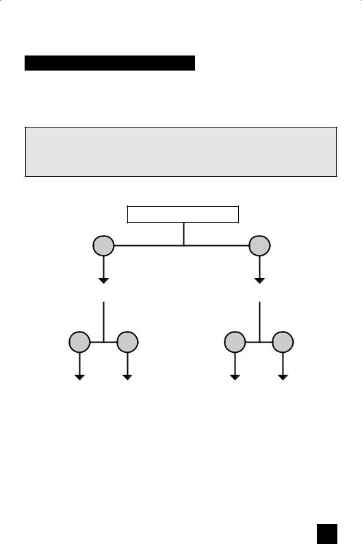
Please follow the flow chart below to determine which connection setup is right for you. Then, refer to the appropriate diagrams to connect your television to other devices that you may have. After you are finished connecting your devices, plug the power cord into the nearest power outlet and turn on the TV.
A VCR is not necessary for operation of the television. If you follow these diagrams and the television does not work properly, contact your local cable operator.
•To connect a DVD player, see Diagram #3. A DVD player is optional.
•If you have a satellite television system, please refer to the satellite TV manual.
Do you use a Cable TV Box?
Yes |
No |
Do you have a VCR? |
|
Do you have a VCR? |
|
|
|
Yes |
No |
Yes |
No |
Diagram #2 Diagram #1 |
Diagram #3 Diagram #1 |
13
Quick Setup |
Connections |
Diagram #1 |
Cable or Antenna |
|
Output |
|
Coaxial Cable |
|
75Ω |
|
(VHF/UHF) |
|
OR |
OUT IN
TV Rear Panel |
Cable Box |
Note:
•If you do not have a cable box, connect the cable wire from the wall outlet into the back of the TV.
Diagram #2
|
AUDIO |
|
AUDIO |
VIDEO |
S-VIDEO |
COMPONENT VIDEO |
|
75Ω |
OUT |
R |
L |
|
Y |
Pb |
Pr |
|
|
|
|
|
|
|
|
(VHF/UHF) |
|
|
|
|
INPUT-3 |
|
|
|
R |
|
|
|
INPUT-2 |
|
|
|
|
|
|
|
|
|
|
OPTICAL OUT |
|
|
|
|
OVER |
|
|
|
|
|
|
|
|
|
|
Digital |
L |
|
|
|
|
|
|
|
|
|
|
INPUT-1 |
|
|
|
Audio |
|
|
|
|
|
|
|
|
|
|
|
OVER |
|
|
|
Cable or Antenna Output
TV Rear Panel
OR
VCR
IN
IN
OUT R L V
OUT
Notes:
OUT IN
Cable Box
OUT OUT |
IN |
Two-Way
Splitter
Coaxial Cable
•If your VCR is a mono sound unit, it will have only one audio out jack. Connect it to the LEFT AUDIO INPUT on the front of the TV.
•Use the S-Video connection if possible for superior picture quality.
•Your VCR must be turned on to view premium cable channels.
14

Quick Setup |
Connections |
|
|
Notes:
•Green, blue and red are the most common colors for DVD cables. Some models may vary colors. Please consult the user’s manual for your DVD player for more information.
•Be careful not to confuse the red DVD cable with the red audio cable. It is best to complete one set of connections (DVD or audio output) before starting the other to avoid accidentally switching the cables.
•You may also connect the DVD player to Input 1.
Diagram #3
Cable or Antenna
Output
VCR
Two-Way Splitter |
IN |
|
|
|
OUT OUT |
R |
L V |
|
|
||
|
IN |
IN |
|
|
|
|
|
|
OUT |
OUT |
|
|
|
|
|
Coaxial Cable |
|
|
OR |
(Attachment) |
|
|
|
AUDIO |
AUDIO |
VIDEO |
S-VIDEO |
|
COMPONENT VIDEO |
|
75Ω |
OUT |
R |
L |
|
Y |
Pb |
Pr |
|
|
|
|
|
|
|
|
(VHF/UHF) |
|
|
|
|
INPUT-3 |
|
|
|
|
|
|
|
|
|
|
|
R |
|
|
|
INPUT-2 |
|
|
|
|
|
|
|
|
|
|
OPTICAL OUT |
|
|
|
OVER |
|
|
|
|
|
|
|
|
|
|
|
Digital |
L |
|
|
|
|
|
|
|
|
|
|
INPUT-1 |
|
|
|
Audio |
|
|
|
OVER |
|
|
|
|
|
|
|
|
|
||
TV Rear Panel
|
Y |
Green |
|
PB |
Blue |
AUDIO OUT |
PR |
Red |
L R |
|
OUT |
DVD Player (OPTIONAL)
15
Quick Setup |
Connections |
|
|
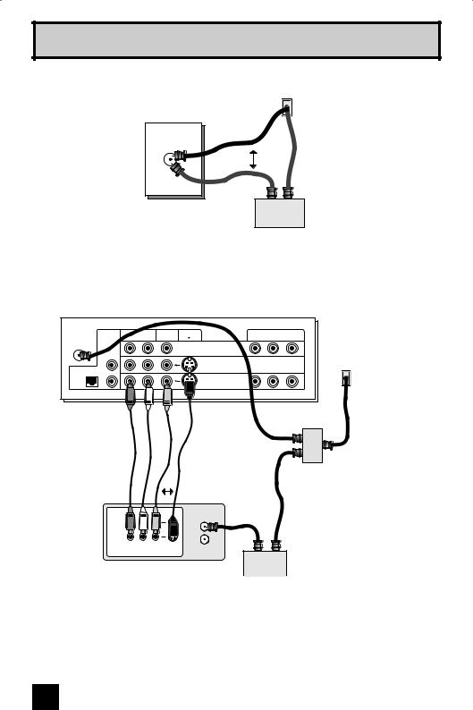
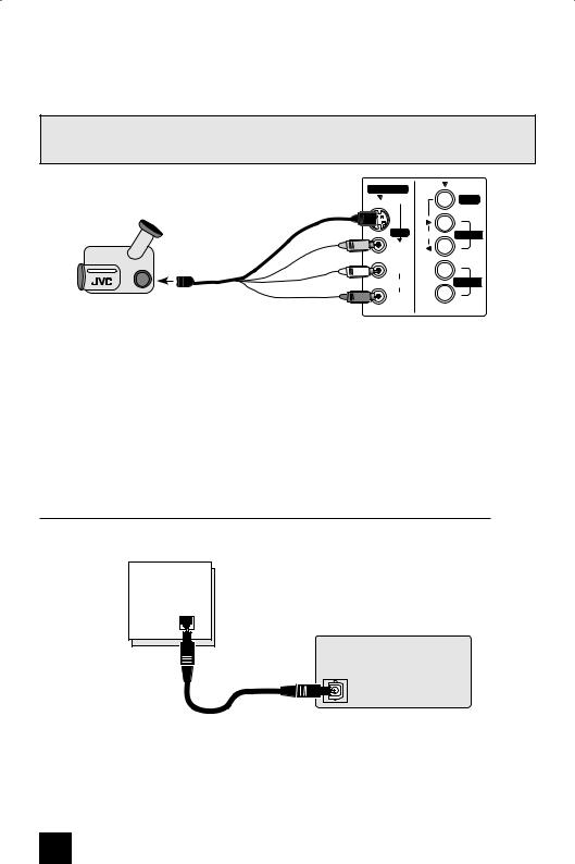
Connecting to a Camcorder
You may connect a camcorder, game console or other equipment to your television by using the input jacks (Input 4) located on the side or front of the television. You can also connect these using the television’s rear input jacks, using the same instructions.
Illustration of AV-30W776
INPUT 4 |
|
S-VIDEO |
MENU |
Camcorder |
- OR - |
+
OVER OPERATE CHANNEL
VIDEO –
L/MONO |
+ |
AUDIO |
VOLUME |
R |
– |
1)Connect a yellow composite cable from the camcorder VIDEO OUT, into the VIDEO IN on the side of the TV, OR connect an S-Video cable from the side of the TV to the camcorder.
2)Connect a white cable from the camcorder LEFT AUDIO OUT, into the LEFT AUDIO IN on the side of the TV.
3)Connect a red cable from the camcorder RIGHT AUDIO OUT, into the RIGHT AUDIO IN on the side of the TV.
Note:
•If your camcorder is a mono sound model it will have only one AUDIO OUT. Connect it to the L/MONO on the side of the TV. (AV-30W776 ONLY). For all the other models, please use the input jacks on the front control panel.
Connecting to an amplifier using your optical output
You can connect an amplifier that has an optical digital input terminal by using an optical digital cable from the optical output. The signal that is output can be PCM or Dolby Digital.
OPTICAL OUT
Digital Audio
TV Rear Panel
Amplifier
1) Connect the optical cable from the back of the TV to the back of the amplifier.
Notes:
•This terminal can only output digital audio.
•In order to use the optical output connection, select PCM or Dolby Digital on Digital Sound in the Digital Setup Menu. See page 63.
•Refer to your owners manual on using your amplifier.
16
Quick Setup |
Connections |
|
|
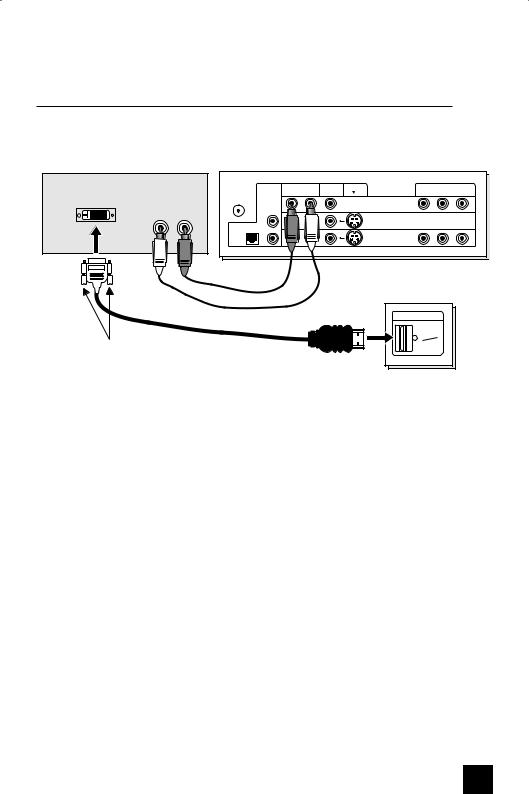
Connecting to a Digital TV Receiver
By connecting a Digital TV Reciever, high definition pictures can be displayed on your TV in their digital form.
DTV Decoder
DIGITAL OUT |
AUDIO OUT |
L R
|
AUDIO |
|
AUDIO |
VIDEO |
S-VIDEO |
COMPONENT VIDEO |
|
75Ω |
OUT |
R |
L |
|
Y |
Pb |
Pr |
|
|
|
|
|
|
|
|
(VHF/UHF) |
|
|
|
|
INPUT-3 |
|
|
|
R |
|
|
|
INPUT-2 |
|
|
|
|
|
|
|
|
|
|
OPTICAL OUT |
|
|
|
|
OVER |
|
|
|
|
|
|
|
|
|
|
Digital |
L |
|
|
|
|
|
|
|
|
|
|
INPUT-1 |
|
|
|
Audio |
|
|
|
|
|
|
|
|
|
|
|
OVER |
|
|
|
HDMI to DVI Cable
After the connections have been made, tighten the screw to secure the cables.
TV Rear Panel
DIGITAL-IN |
VIDEO |
(DIGITAL) |
AUDIO |
(DIGITAL) |
1)Connect the HDMI to DVI Cable from the DIGITAL OUT on the back of your DTV decoder, to the DIGITAL-IN on the back of your television.
2)Connect a red cable from the DTV decoder RIGHT AUDIO OUT, to the RIGHT AUDIO IN into VIDEO-3 on the back of your television.
3)Connect a white cable from the DTV decoder LEFT AUDIO OUT, to the LEFT AUDIO IN into
VIDEO-3 on the back of your television.
•The digital-in terminal is not compatible with the picture signal of a personal computer.
•Use a HDMI to DVI cable (commercially available) in order to digitally connect the television with a DTV decoder.
Notes:
•If 480p signals (640x480 or 720x480) are displayed on the screen, the horizontal balance may be slightly shifted. Access the “DIGITAL-IN” in the initial setup menu to adjust it. (Refer to page 46.)
•When you do the above connection, set DIGITAL-IN AUDIO in the Initial Setup menu to ANALOG. See "DIGITAL-IN AUDIO", page 46.
17
Quick Setup |
Connections |
|
|
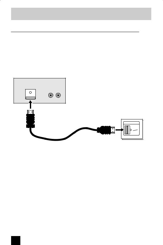
Connecting to a HDMI Compatible Device
By connecting a HDMI compatible device, high definition pictures can be displayed on your
TV in their digital form. Some HDMI devices can include DVD players, D-VHS or any HDMI compatible device.
HDMI (High Definition Multimedia Interface) is the first industry supported, uncompressed, all digital audio/video interface. HDMI provides and interface between any audio/video source, such as a set-top box, DVD player, A/V receiver or an audio and/or video monitor, such as a digital television (DTV).
HDMI Compatible Device
DIGITAL OUT |
AUDIO OUT |
LR
TV Rear Panel
HDMI Cable
DIGITAL-IN |
VIDEO |
(DIGITAL) |
AUDIO |
(DIGITAL) |
1)Connect the HDMI Cable from the DIGITAL OUT on the back of your DTV or HDMI device, to the DIGITAL-IN on the back of your television.
Note:
•When you do the above connection, set DIGITAL-IN AUDIO in the Initial Setup menu to
DIGITAL. See "DIGITAL-IN AUDIO", page 46.
•If the HDMI output device signal is changed (for example, 480i/60Hz is changed to 480p/60Hz), the screen may turn green and there may be some distortion for a short time until the signal becomes stable.
18

Quick Setup |
Connections |
|
|
Connecting to an AV Receiver using your television's V1 Smart Input
By connecting your AV Receiver to your television's V1 Smart Input, you can watch picture sources from many different devices, without having to change or use the other input connections on your TV. This allows you to free up the other input connections so you can connect more devices to your television.
AV Receiver
MONITOR |
Y |
|
OUT |
||
|
||
|
PB |
|
|
PR |
|
|
MONITOR OUT |
TV Rear Panel
|
AUDIO |
|
AUDIO |
VIDEO |
S-VIDEO |
COMPONENT VIDEO |
|
75Ω |
OUT |
R |
L |
|
Y |
Pb |
Pr |
|
|
|
|
|
|
|
|
(VHF/UHF) |
|
|
|
|
INPUT-3 |
|
|
|
R |
|
|
|
INPUT-2 |
|
|
|
|
|
|
|
|
|
|
OPTICAL OUT |
|
|
|
|
OVER |
|
|
|
|
|
|
|
|
|
|
Digital |
L |
|
|
|
|
|
|
|
|
|
|
INPUT-1 |
|
|
|
Audio |
|
|
|
|
|
|
|
|
|
|
|
OVER |
|
|
|
1)Connect an S-Video Cable from the AV Receiver's MONITOR OUT, to the S-Video INPUT-1 on the back of your television.
2)Connect a Yellow Component Cable from the AV Receiver's MONITOR OUT, into the VIDEO INPUT-1 on the back of your television.
3)Connect a Green Component Cable from the AV Receiver's Y MONITOR OUT, into the Y VIDEO INPUT-1 on the back of your television.
4)Connect a Blue Component Cable from the AV Receiver's Pb MONITOR OUT, into the
Pb VIDEO INPUT-1 on the back of your television.
5)Connect a Red Component Cable from the AV Receiver's Pr MONITOR OUT, into the Pr VIDEO INPUT-1 on the back of your television.
Notes:
•Please refer to your AV Receiver instruction manual for more information on connecting your speakers and other devices like a DVD player.
•Use your AV Receiver's remote to switch to the different devices you have connected.
•Some AV Receivers may not respond when the V1 Smart Input function is turned on.
•If you have video connections for each input device connected to your AV Receiver, you should not connect them using both S-Video and Composite connection at the same time when you are using V1 Input as the V1 Smart Input. In this case we recommend using the S-Video connection.
19

Quick Setup |
Plug-In Menu |
|
|
Step 3 – The Interactive Plug In Menu
When you turn your television on for the first time the interactive plug-in menu will appear. The plug-in menu helps you to get your TV ready to use by letting you set your preferences for:
•The language in which you want the onscreen menus to appear.
•Setting the TV’s clock to the correct time so your timer functions will work properly. You can choose “AUTO” or “MANUAL” for setting the clock.
•The auto tuner setup of which channels you wish to receive.
We recommend you complete the interactive plug-in items before you start using your television.
Notes:
•The interactive plug-in menu setting does not appear if your TV has been turned on before.
In this case use the onscreen menus to perform these settings. See pages 39, 50 and 30.
•If you press the Menu button while setting up the interactive plug-in menu, it will skip over it.
Language
After the “JVC INTERACTIVE PLUG IN MENU” has been displayed, the TV automatically switches to the LANGUAGE settings. You can choose to view your onscreen menus in three languages: English, French (Français) or Spanish (Español).
LANGUAGE/LANGUE/IDIOMA |
|
|
|
|
|
|
|
|
ENGLISH |
|
|
|
NEXT |
|
|
|
|
|
|
|
SELECT OPERATE |
MENU EXIT |
|
|
|
|
|
è To choose a language:
(English, Français or Español)
†To NEXT (To set clock)
(To be continued...)
20
Quick Setup |
Plug-In Menu |
|
|
Auto Clock Set
Before you use any of your TV’s timer functions, you must first set the clock. You may precisely set your clock using the XDS time signal broadcast by most public analog broadcasting stations. If you do not have this in your area, you will have to set the clock manually. See manual clock set below. To set the clock using the XDS signal:
|
|
|
|
è |
To choose AUTO |
SET CLOCK |
|
|
|||
|
|
|
|
† |
To TIME ZONE |
|
|
|
|
||
|
|
|
|
è |
To select your time zone: (Atlantic, Eastern, |
|
MODE |
AUTO |
|
Central, Mountain, Pacific, Alaska or |
|
|
TIME |
-- : -- -- |
|
|
Hawaii) |
|
TIME ZONE |
ATLANTIC |
|
† |
To move to D.S.T. (Daylight Savings Time) |
|
D.S.T. |
ON |
|
||
|
|
è |
To turn D.S.T. ON or OFF |
||
|
|
|
|
||
|
NEXT |
|
|
† |
To NEXT (To Auto Tuner Setup) |
|
|
|
|
|
|
|
SELECT OPERATE |
MENU EXIT |
|
|
|
Notes:
•D.S.T. can be used when it is set to ON in the SET CLOCK menu.
•Only when the MODE is set to AUTO, the Daylight Savings Time feature automatically adjusts your TV’s clock for Daylight Savings. The clock will move forward one hour at 2:00 am on the first Sunday in April. The clock will move back one hour at 2:00 am on the last
Sunday in October.
•You will have to reset the clock after a power interruption. You must set the clock before operating any timer functions.
Manual Clock Set
To set your clock manually (without using the XDS signal), choose MANUAL. If you choose AUTO, see auto clock set above.
|
|
|
|
|
è |
To choose MANUAL |
SET CLOCK |
|
|
|
|||
|
|
|
|
|
† |
To TIME |
|
|
|
|
|
è |
To set the hour |
|
|
|
|
|
† |
To minute |
|
MODE |
|
MANUAL |
|||
|
TIME |
|
-- : -- -- |
|
è |
To set the minute |
|
TIME ZONE |
|
ATLANTIC |
|
† |
To TIME ZONE |
|
D.S.T. |
|
ON |
|
è |
To select your time zone: (Atlantic, Eastern, |
|
|
START CLOCK |
|
Central, Mountain, Pacific, Alaska or |
||
|
|
|
Hawaii) |
|||
|
|
|
|
|
|
To move to D.S.T. (Daylight Savings Time) |
|
SELECT |
OPERATE |
MENU EXIT |
† |
||
|
|
|
|
|
è |
To turn D.S.T. ON or OFF |
|
|
|
|
|
† |
To START CLOCK |
Note:
•You will have to reset the clock after a power interruption. You must set the clock before operating any timer functions.
(To be continued...)
21
Quick Setup |
Plug-In Menu |
|
|
Auto Tuner Setup
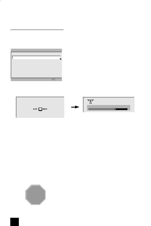
In auto tuner setup, the TV automatically scans through all available channels, memorizing the active ones and skipping over blank ones or channels with weak signals. This means when you scan (using the CHANNEL +/– buttons) you will receive only clear, active channels.
AUTO TUNER SETUP
TUNER MODE  AIR
AIR 

 START
START
 SELECT
 OPERATE MENU EXIT
è To choose CABLE or AIR (or SKIP when you skip AUTO TUNER SETUP)
†To START
After Analog Auto Tuner Setup is finished, Digital Auto
Tuner Setup starts.
NOW |
Now Programming... |
|
PROGRAMMING ! |
||
20 |
||
|
48
When the setup is finished, "THANK YOU ! SETUP IS NOW COMPLETE" is displayed. Your quick setup is now complete. You can now begin watching your television, or you can continue on in this guide for more information on programming your remote control, or using the
JVC onscreen menu system to customize your television viewing experience.
Notes:
•If you want to cancel the Auto Tuner Setup, press the MENU button.
•Noise muting will not work during Auto Tuner Setup.
•If you choose SKIP, it finished without doing the Auto Tuner Setup.
Cable Box and Satellite Users: After your auto tuner setup is complete, you may, (depending on the type of hookup), have only 1 channel, usually 3 or 4 in the auto tuner memory. This is normal.
STOP The Quick Setup is complete
22

Remote Programming
Setting the CATV, VCR and DVD Codes
You can program your remote to operate your cable box, satellite receiver, VCR or DVD player by using the instructions and codes listed below. If the equipment does not respond to any of the codes listed below or to the code search function, use the remote control supplied by the manufacturer.
Cable Box or Satellite Codes
The remote control is programmed with cable box and satellite codes for power on/off, channel up/down, and 10 key operation.
1)Find the cable box or satellite brand from the list of codes shown below.
2)Slide the 2-way selector switch to “CATV”.
3)Press and hold down the DISPLAY button, then enter the first code number listed with the 10 key pad.
4)Release the DISPLAY button, and confirm the operation of the cable box/satellite receiver.
•If your cable or satellite box does not respond to the first code, try the others listed. If it does not respond to any code, try the search codes function, on page 26.
Cable Box |
CODES |
Cable Box |
CODES |
Digital |
CODES |
|
|
|
|
|
|
|
|
ABC |
024 |
Puser |
032 |
Satellite |
|
|
Systems |
|
|||||
|
|
|
|
|
||
Archer |
032, 025 |
RCA |
061, 070 |
Echostar |
100, 113, 114, |
|
|
|
|
|
|||
Cableview |
051, 032 |
Realistic |
032 |
|||
|
115 |
|||||
|
|
|
|
|
||
Citizen |
022, 051 |
Regal |
058, 064, 040, |
|
|
|
Express VU |
100, 113 |
|||||
|
|
|
041, 042, 045, |
|||
Curtis |
058, 059 |
|
|
|
||
|
068 |
G.E. |
106 |
|||
|
|
|
||||
Diamond |
024, 032, 025 |
|
||||
Regency |
034 |
|
|
|||
|
|
G.I. |
108 |
|||
Eagle |
029 |
|||||
|
|
|||||
Rembrandt |
037, 032, 051, |
|
|
|||
|
|
Gradiente |
112 |
|||
Eastern |
034 |
|
038 |
|||
|
|
|
|
|
||
GC Brand |
032, 051 |
|
|
Hitachi |
104, 111 |
|
Samsung |
051 |
|||||
Gemini |
022, 043 |
|
|
|
|
|
Scientific Atlanta |
057, 058, 059 |
HNS (Hughes) |
104 |
|||
|
|
|||||
General Instrument |
065, 024, 025, |
|||||
|
|
|
|
|||
SLMark |
051, 047 |
Panasonic |
105 |
|||
|
026, 027, 020, |
|||||
|
021, 022, 057, |
Sprucer |
051, 056 |
Philips |
102, 103 |
|
|
023 |
Stargate |
032, 051 |
|
|
|
|
Primestar |
108 |
||||
Hamlin |
040, 041, 042, |
|||||
Telecaption |
067 |
Proscan |
106, 109, 110 |
|||
|
045, 058, 064 |
|||||
Hitachi |
049, 024 |
Teleview |
047, 051 |
RCA |
106, 109, 110 |
|
Jerrold |
065, 024, 025, |
|
|
|
|
|
Texscan |
044 |
Sony |
107 |
|||
|
026, 027, 020, |
|||||
|
|
|
|
|
||
|
021, 022, 057, |
Tocom |
035, 036, 066 |
Star Choice |
104, 108 |
|
|
023 |
Toshiba |
050 |
Toshiba |
101 |
|
|
|
|||||
Macom |
049, 050, 051, |
|
|
|
|
|
Unika |
032, 025 |
Uniden |
102, 103 |
|||
|
054 |
|
|
|
|
|
|
Universal |
022, 032 |
|
|
||
Magnavox |
033 |
|
|
|||
|
|
|
|
|||
Videoway |
052 |
|
|
|||
|
|
|
|
|||
Memorex |
030 |
|
|
|||
|
|
|
|
|||
|
|
Viewstar |
029, 030 |
|
|
|
Movietime |
032, 051 |
|
|
|||
|
|
|
|
|
|
|
Oak |
039, 037, 048 |
Zenith |
063, 046 |
|
|
|
|
|
|
|
|
|
|
Panasonic |
055, 056, 060, |
Zenith/Drake |
046 |
|
|
|
|
071, 073 |
Satellite |
|
|
|
|
Paragon |
063 |
|
|
|
|
|
|
|
|
|
|
|
|
Philips |
028, 029, 030, |
|
|
|
|
|
|
052, 053, 031, |
|
|
|
|
|
|
069 |
|
|
|
|
|
|
|
|
|
|
|
|
Pioneer |
047, 062 |
|
|
|
|
|
|
|
|
|
|
|
|
Pulsar |
051, 032 |
|
|
|
|
|
|
|
|
|
|
|
23

Remote Programming
VCR Codes
The remote control is programmed with VCR codes for power on/off, play, stop, fast-forward, rewind, pause, record, channel up/down operation.
1)Find the VCR brand from the list of codes shown below.
2)Slide the first 2-way selector switch to “TV” and the other 2-way selector switch to “VCR”.
3)Press and hold down the DISPLAY button, then enter the first code number listed with the 10 key pad.
4)Release the DISPLAY button, and confirm the operation of the VCR.
•If your VCR does not respond to the first code, try the others listed. If it does not respond to any of the codes, try the search codes function on page 26.
•After you program your remote, some VCR buttons may not work properly. If so, use the
VCR’s remote.
•To record, hold down the REC button on the remote and press PLAY.
VCRs |
CODES |
VCRs |
|
CODES |
VCRs |
CODES |
|
Admiral |
035 |
Marantz |
|
003, 004, 005 |
Samsung |
037, 060, 062, |
|
Aiwa |
027, 032, 095 |
Marta |
|
064 |
|
033, 089 |
|
|
|
|
|
|
Samtron |
089 |
|
Akai |
029, 072, 073, |
Memorex |
|
024, 067 |
|||
|
|
|
|||||
|
074 |
|
|
|
Sansui |
003, 026, 020, |
|
|
MGA |
|
038, 040, 047, |
||||
Audio Dynamic |
003, 005 |
|
|
048, 041, 042 |
|
052 |
|
|
|
|
|
|
Sanyo |
063, 067, 091, |
|
Bell & Howell |
063, 071 |
Minolta |
|
058, 045, 093 |
|||
|
|
071 |
|||||
Broksonic |
020, 026, 094 |
Mitsubishi |
|
038, 040, 047, |
|
||
|
Scott |
059, 060, 062, |
|||||
Canon |
023, 025 |
|
|
048, 041, 042, |
|||
|
|
|
067, 038, 040, |
||||
|
|
078, 090 |
|
||||
CCE |
043 |
|
|
|
047, 048, 026, |
||
Multitech |
|
047, 027, 062 |
|
||||
Citizen |
064 |
|
|
020 |
|||
|
|
|
|
||||
NEC |
|
003, 004, 005, |
|
||||
|
|
|
Sears |
063, 064, 065, |
|||
Craig |
063, 029, 064 |
||||||
|
|
|
|
000 |
|
066, 058, 000, |
|
Curtis Mathes |
045, 024, 027, |
|
|
||||
Olympic |
|
024, 023 |
|
001 |
|||
|
093 |
|
|
||||
|
Optimus |
|
028, 021, 035, |
Shintom |
075 |
||
Daewoo |
043, 059, 024, |
|
|||||
|
|
064 |
Sharp |
035, 036, 080, |
|||
|
092 |
|
|
||||
|
Orion |
|
026, 020 |
||||
DBX |
003, 004, 005 |
|
|
088 |
|||
|
|
Panasonic |
|
023, 024, 021, |
Signature 2000 |
027, 035 |
|
Dimensia |
045, 093 |
||||||
|
|
022 |
Singer |
075 |
|||
|
|
|
|
||||
Emerson |
043, 026, 077, |
|
|||||
Penney |
|
024, 058, 045, |
|||||
|
Sony |
028, 029, 030, |
|||||
|
061, 025, 042, |
|
|||||
|
|
|
063, 003, 004, |
||||
|
020, 076 |
|
|
|
053, 054, 055 |
||
|
|
|
005, 093 |
|
|||
Fisher |
063, 066, 067, |
|
|
SV 2000 |
027 |
||
Pentax |
|
058, 005, 045, |
|||||
|
065, 071, 091 |
|
Sylvania |
031, 023, 024, |
|||
|
|
|
093 |
||||
Funai |
027, 026, 020, |
|
|
|
|
027 |
|
Philco |
|
031, 024, 027, |
|
||||
|
Symphonic |
027, 081 |
|||||
|
000 |
|
|
023, 026, 020, |
|||
G.E. |
033, 045, 024 |
|
|
043 |
Tashiro |
064 |
|
Go Video |
037, 051, 049, |
Philips |
|
031, 023, 024, |
Tatung |
003, 004, 005 |
|
|
050, 089 |
|
|
086 |
Teac |
003, 004, 027, |
|
|
|
Pioneer |
|
023 |
|
005 |
|
Goldstar |
064 |
|
|||||
|
|
Proscan |
|
045, 058, 023, |
Technics |
021, 022, 023, |
|
Gradiente |
083, 084, 081, |
||||||
|
|
024, 031, 046, |
|
024 |
|||
|
000, 001 |
|
|
|
|||
|
|
|
|
059, 060, 033, |
Teknika |
024, 027, 070 |
|
Hitachi |
023, 045, 058, |
|
|||||
|
|
087, 093 |
|||||
|
|
|
|
||||
|
|
Toshiba |
059, 046, 079 |
||||
|
027, 081, 093 |
|
|
|
|||
|
Quasar |
|
021, 022, 023, |
||||
|
|
|
Vector Research |
005 |
|||
Instant Replay |
024, 023 |
|
|
024 |
|||
|
|
|
|
||||
|
|
Wards |
035, 036, 067, |
||||
|
|
Radio Shack |
|
033, 024, 063, |
|||
Jensen |
003 |
|
|||||
|
|
044, 064 |
|||||
|
|
036, 067, 040, |
|
||||
|
|
|
|
|
|||
JVC |
000, 001, 002, |
|
|
|
|
||
|
|
027 |
Yamaha |
063, 003, 004, |
|||
|
003, 004, 005 |
|
|
||||
|
RCA |
|
033, 045, 058, |
|
005 |
||
|
|
|
|
||||
Kenwood |
003, 004, 064, |
|
|
023, 024, 031, |
Zenith |
044, 082, 064, |
|
|
005 |
|
|
046, 059, 060, |
|
094 |
|
LXI |
027, 064, 058, |
|
|
083, 084, 085, |
|
|
|
|
|
087, 093 |
|
|
|||
|
065, 066, 063, |
|
|
|
|
||
|
067 |
Realistic |
|
024, 063, 036, |
|
|
|
Magnavox |
031, 023, 024, |
|
|
067, 040, 027 |
|
|
|
|
086 |
|
|
|
|
|
|
|
|
|
|
|
|
|
24
Loading...