


RM-C755
Model Number
Serial Number
NOTE TOTHE CUSTOMER:
In the spaces below, enter the model and serial number
for your television (located on the rear of the television cabinet).
Staple your sales receipt or invoice to the inside cover of this guide.
Keep this user’s guide in a convenient place for future reference.
Keep the carton and original packaging for future use.
For Models:
AV-36950
AV-35955
AV-32950
AV-27950
Color Television
User’s Guide
Illustration of AV-32950 and RM-C755
IMPORTANT SAFEGUARDS
CAUTION:
Please read and retain for your safety.
Electrical energy can perform many useful functions. This TV
set has been engineered and manufactured to assure your
personal safety. But improper use can result in potential
electrical shock or fire hazards. In order not to defeat the
safeguards incorporated in this TV set, observe the following
basic rules for its installation, use and servicing.
And also follow all warnings and instructions marked on your
TV set.
INSTALLATION
1 Your TV set is equipped with a polarized AC line plug (one
blade of the plug is wider than the other).
This safety feature allows the plug to fit into the power
outlet only one way. Should you be unable to insert the
plug fully into the outlet, try reversing the plug.
Should it still fail to fit, contact your electrician.
2 Operate the TV set only from a power source as indicated
on the TV set or refer to the operating instructions for this
information. If you are not sure of the type of power supply
to your home, consult your TV set dealer or local power
company. For battery operation, refer to the operating
instructions.
3 Overloaded AC outlets and extension cords are danger-
ous, and so are frayed power cords and broken plugs.
They may result in a shock or fire hazard. Call your service
technician for replacement.
4 Do not allow anything to rest on or roll over the power
cord, and do not place the TV set where power cord is
subject to traffic or abuse. This may result in a shock or
fire hazard.
5 Do not use this TV set near water — for example, near a
bathtub, washbowl, kitchen sink, or laundry tub, in a wet
basement, or near swimming pool, etc.
IMPORTANT SAFETY PRECAUTIONS
CAUTION
RISK OF ELECTRIC SHOCK
DO NOT OPEN
C AU T I O N :To reduce the risk of electric shock .
do not remove cover (or back ) .
No user serv i c e a ble parts inside.
R e fer servicing to qualified service pers o n n e l .
(POLARIZED-TYPE)
The lightning flash with arrowhead symbol,
within an equilateral triangle is intended to
a l e rt the user to the presence of uninsulated
“ d a n g e rous voltage” within the pro d u c t ’s
e n c l o s u re that may be of sufficient magnitude
to constitute a risk of electric shock to
p e r s o n s .
The exclamation point within an equilateral
triangle is intended to alert the user to the
presence of important operating and mainte-
nance (servicing) instructions in the literature
accompanying the appliance.
HAZARDS, DO NOT EXPOSE THIS TV
SET TO RAIN OR MOISTURE.
OBSERVE THE FOLLOWING RULES
REGARDING THE USE OF THIS UNIT.
1. Operate only from the power source specified
on the unit.
2. Avoid damaging the AC plug and power cord .
3. Avoid Improper installation and never position
the unit where good ventilation is unattain-
able.
4. Do not allow objects or liquid into the cabinet
openings.
5. In the event of trouble, unplug the unit and
call a service technician. Do not attempt to
repair it yourself or remove the rear cover.
Changes or modifications not approved by JVC
could void the warranty.
* When you don’t use this TV set for a long
period of time, be sure to disconnect both the
power plug from the AC outlet and antenna for
your safety.
* To prevent electric shock do not use this
polarized plug with an extension cord, recepta-
cle or other outlet unless the blades can be fully
inserted to prevent blade exposure.
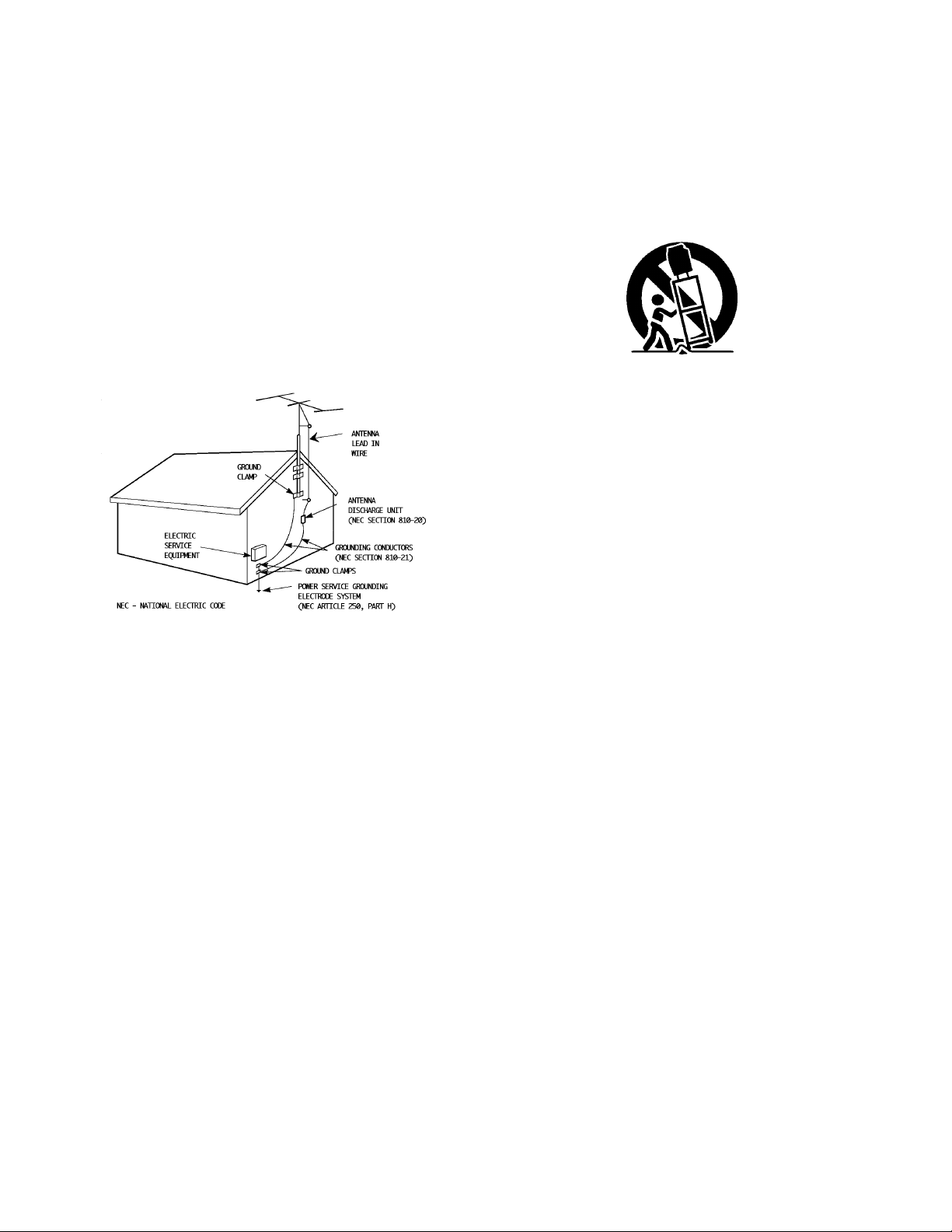
6 If an outside antenna is connected to the TV set, be sure the
antenna system is grounded so as to provide some pro t e c t i o n
against voltage surges and built-up static charges. Section 810
of the National Electrical Code provides information with re s p e c t
to proper grounding of the mast and supporting stru c t u re ,
g rounding of the lead-in wire to an antenna discharge unit, size
of grounding conductors, location of antenna discharge unit,
connection re q u i rements for the grounding electro d e .
7 An outside antenna system should not be located in the
vicinity of overhead power lines or other electric light or
power circuits, or where it can fall into such power lines or
circuits. When installing an outside antenna system, extreme
care should be taken to keep from touching such power
lines or circuits as contact with them might be fatal.
8 TV sets are provided with ventilation openings in the cabinet
to allow heat generated during operation to be released.
Therefore:
— Never block the bottom ventilation slots of a portable TV
set by placing it on a bed, sofa, rug, etc.
— Never place a TV set in a “built-in” enclosure unless
proper ventilation is provided.
— Never cover the openings with a cloth or other material.
— Never place the TV set near or over a radiator or heat re g i s t e r.
9 To avoid personal injury:
— Do not place a TVset on a sloping shelf unless properly secure d .
— Use only a cart or stand recommended by the TV s e t
m a n u f a c t u re r.
— Do not try to roll a cart with small casters across thresh-
olds or deep pile carpets.
— Wall or shelf mounting should follow the manufacturer’s
instructions, and should use a mounting kit approved by
the manufacturer.
USE
10 Caution children about dropping or pushing objects into the TV set
t h rough cabinet openings. Some internal parts carry hazard o u s
voltages and contact can result in a fire or electrical shock.
11 Unplug the TV set from the wall outlet before cleaning. Do
not use liquid or an aerosol cleaner.
12 Never add accessories to a TV set that has not been designed for
this purpose. Such additions may result in a hazard .
13 For added protection of the TVset during a lightning storm or
when the TV set is to be left unattended for an extended period
of time, unplug it from the wall outlet and disconnect the
antenna. This will prevent damage to product due to lightning
s t o rms or power line surg e s .
14 A TVset and cart combination should be moved with care .
Quick stops, excessive force, and uneven surfaces may cause
the TV set and cart combination to overt u rn .
SERVICE
15 Unplug this TV set from the wall outlet and refer servicing to
q u a l i fied service personnel under the following conditions:
A. When the power cord or plug is damaged or frayed.
B. If liquid has been spilled into the TV set.
C. If the TV set has been exposed to rain or water.
D. If the TV set does not operate normally by following the
operating instructions. Adjust only those controls that are
c o v e red in the operating instructions as improper adjust-
ment of other controls may result in damage and will often
re q u i re extensive work by a qualified technician to re s t o re
the TV set to normal operation.
E. If the TVset has been dropped or damaged in any way.
F. When the TV set exhibits a distinct change in perfor-
mance — this indicates a need for service.
1 6 Do not attempt to service this TVset yourself as opening or
removing covers may expose you to dangerous voltage or
other hazards. Refer all servicing to qualified service personnel.
17 When replacement parts are re q u i red, have the serv i c e
technician verify in writing that the replacement parts he uses
have the same safety characteristics as the original part s .
Use of manufacture r’s specified replacement parts can
p revent fire, shock, or other hazard s .
18 Upon completion of any service or repairs to this TVs e t ,
please ask the service technician to perf o rm the safety check
described in the manufacture r’s service literature .
19 When a TV set reaches the end of its useful life, impro p e r
disposal could result in a picture tube implosion. Ask a
q u a l i fied service technician to dispose of the TV set.
20 Note to CATV system installer.
This reminder is provided to call the CATV system installer’s
attention to Article 820-40 of the NEC that provides
guidelines for proper grounding and, in particular, specifies
that the cable ground shall be connected to the grounding
system of the building, as close to the point of cable entry
as practical.
EXAMPLE OF ANTENNA GROUNDING
AS PER NATIONAL ELECTRICAL CODE

CONNECTIONS
Connections Checklist . . . . . . . . . . . . . . . . 5
Front & Rear Panel Diagrams . . . . . . . . . . . . 5
Cable & VCR Connections . . . . . . . . . . . . . . 6
Audio/Video Connections — Stereo . . . . . . . . . 7
Connecting to a Camcorder . . . . . . . . . . . . . 8
Connecting to an External Amplifier . . . . . . . . . 8
Connecting to JVC AV Compu Link
Capable Components . . . . . . . . . . . . . . . 9
GETTING STARTED
Remote Control . . . . . . . . . . . . . . . . . . . 10
Power . . . . . . . . . . . . . . . . . . . . . . . . . 11
Adjusting Volume . . . . . . . . . . . . . . . . . . 11
Changing Channels . . . . . . . . . . . . . . . . . 11
Setting the CATV and VCR codes . . . . . . . . . 12
MENU FUNCTIONS
Symbols Used in this Guide . . . . . . . . . . . . 14
Onscreen Menus. . . . . . . . . . . . . . . . . . . 14
Plug In Menu . . . . . . . . . . . . . . . . . . . . . 15
Language
Auto Tuner Setup
Set Clock . . . . . . . . . . . . . . . . . . 16
Finish
Initial Setup . . . . . . . . . . . . . . . . . . . . . 17
Channel Summary
Channel Guard-Lock
Picture Adjust . . . . . . . . . . . . . . . . . . . . 18
Tint
Color
Picture
Bright
Detail
Notch
Noise Muting
Set Video Status
Sound Adjust . . . . . . . . . . . . . . . . . . . . . 19
Bass
Treble
Balance
MTS (Multi-channel Stereo Sound)
Some Sound Advice
Clock/Timers . . . . . . . . . . . . . . . . . . . . . 20
On/Off Timer
Set Lock Code
Initial Setup . . . . . . . . . . . . . . . . . . . . . . 21
TV Speaker
Audio Out
Closed Caption
BUTTON FUNCTIONS
Display . . . . . . . . . . . . . . . . . . . . . . . . 2 2
Closed Caption . . . . . . . . . . . . . . . . . . . . 22
Video Status . . . . . . . . . . . . . . . . . . . . . 22
Sleep Timer . . . . . . . . . . . . . . . . . . . . . . 22
Hyper Surround . . . . . . . . . . . . . . . . . . . 23
T V / Video . . . . . . . . . . . . . . . . . . . . . . . 2 3
100+ . . . . . . . . . . . . . . . . . . . . . . . . . . 23
VCR Buttons . . . . . . . . . . . . . . . . . . . . . 23
Menu Buttons . . . . . . . . . . . . . . . . . . . . . 23
Muting . . . . . . . . . . . . . . . . . . . . . . . . . 23
R e t u rn +. . . . . . . . . . . . . . . . . . . . . . . 2 3
Number Buttons (10 Key Pad) . . . . . . . . . . . 23
PIP (Picture In Picture) . . . . . . . . . . . . . . . . 24
Channel -/+ for PIP . . . . . . . . . . . . . . . . . . 24
S o u rce . . . . . . . . . . . . . . . . . . . . . . . . 2 4
Freeze . . . . . . . . . . . . . . . . . . . . . . . . . 24
Swap . . . . . . . . . . . . . . . . . . . . . . . . . 2 4
Move . . . . . . . . . . . . . . . . . . . . . . . . . 2 4
APPENDICES
Troubleshooting . . . . . . . . . . . . . . . . . . . 2 5
Limited Warranty . . . . . . . . . . . . . . . . . . . 26
Authorized Service Centers . . . . . . . . . . . . . 27
S p e c i fications . . . . . . . . . . . . . . . . . . . . 2 8
WELCOME!
Congratulations on your new television purchase! We thank you for choosing JVC.
We know you are anxious to start watching your new television, but before you operate it,
please read this guide and then keep it handy for future re f e rence. After all, you just bought a gre a t
TV with a lot of terr i fic features, you should know what each feature is and how to use it pro p e r l y !
Please note that the illustrations, diagrams, and menu pictures are not exact replicas of the
actual television features. They are for reference only.
Again, congratulations and thank you for choosing JVC! Enjoy!
TABLE OF CONTENTS
C O N N E C T I O N S 5
1) Refer to the connection instructions in the user’s
guide for each component you plan to connect.
They will provide more detailed information about
their products, and they will tell you what plugs and
cables are required.
2) Most A/V input jacks and plugs are color coded:
• Yellow plugs are Video connections
• Red plugs are for Right Audio connections
• White plugs are Left Audio (Mono) connections
3) Perform one hookup at a time.
If you have many accessories to connect, make sure
each connection is correct by checking to see that it
works properly before attempting the next connection.
(For example, always start with the RF or Cable
connections, make sure it works, then move on to
video or VCR connections.)
4) Unplug the power cord between each connection.
5) Each jack on the back of the TV is labeled. If you
read these instructions and still do not fully under-
stand the connections process, seek assistance.
6) The AV Compu Link Cable is supplied with the
JVC device which you want to connect. If you do
not have one, but you do have a JVC Compu Link
capable VCR or HiFi, contact your local JVC dealer.
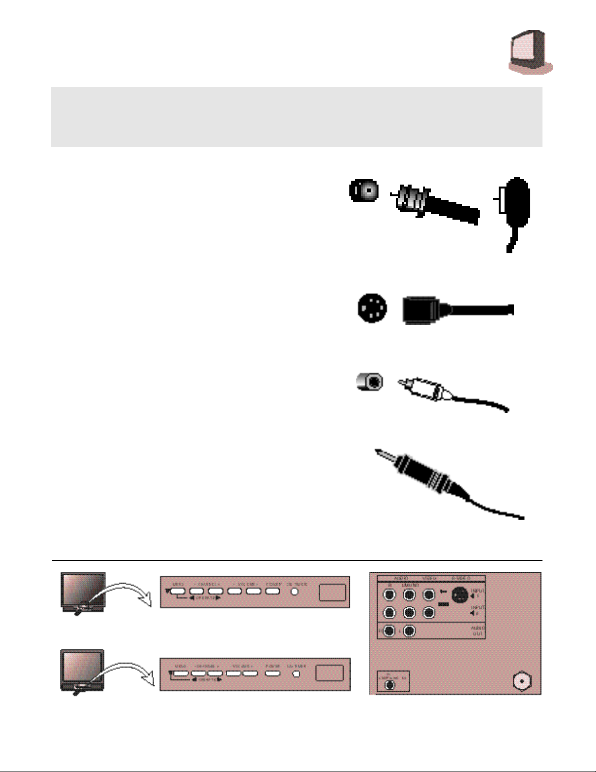
RF Connectors
AV Compu Link Cable
A/V Input Plug
S-Video Plug
The Connections Checklist — Read Me First! section of this guide is a list of ideas to keep in mind when you
set out to perform your connections. It is designed to help us not-so-technically-advanced individuals. If you
read this section, and can’t identify the plugs, connectors, and components you have, do not be afraid to
seek help.
FRONT & REAR PANEL DIAGRAMS
FRONT PANEL DIAGRAM
AV-32950 • AV-27950
FRONT PANEL DIAGRAM
AV-36950 • AV-35955
REAR PANEL DIAGRAM
Common to all models in this book.
6 C O N N E C T I O N S
#1
#2
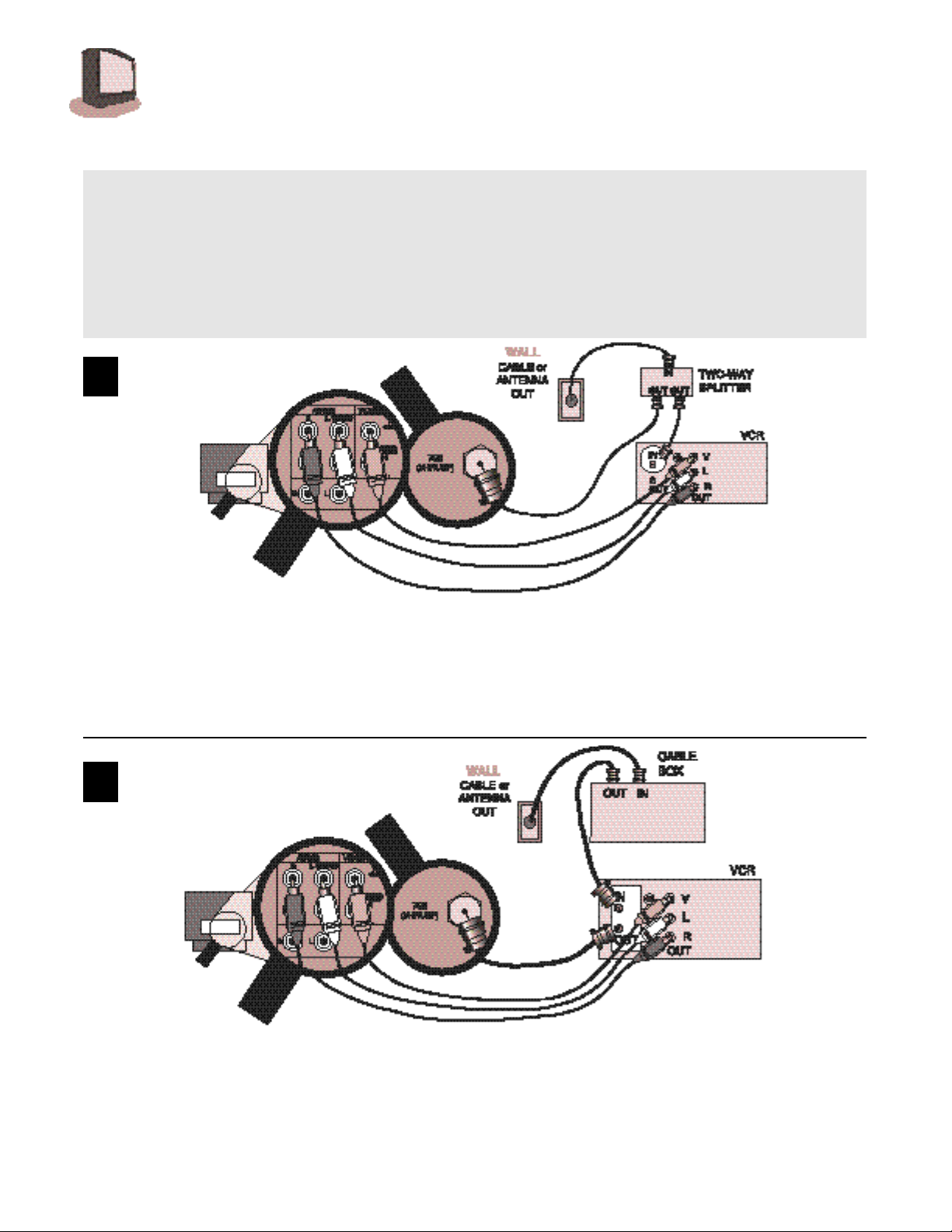
CABLE & VCR CONNECTIONS
T h e re are two basic types of antenna or cable hookups. If you have an antenna, or have a cable TV
system that does not re q u i re you to use a cable box to tune channels, use D i ag r a m # 1 .If you have a
cable system that re q u i res you to use a cable box to access all channels, use D i agram #2. If you have
a cable system that re q u i res you to use a cable box to access certain premium channels, but not
regular basic channels, use D i agram # 3 .
N OT E : To get stereo sound from a hi-fi s t e reo VCR, you must connect it to the TVwith Audio/Video cables. Also, t o
get the best picture quality from any VCR use Audio/Video cables. (Use them! You’ll be glad you did.)
1) Connect cable or antenna RF wire out from the wall, in to the splitter RF input.
2) Connect RF wire Out from the splitter RF output, in to the VCR RF input.
3) Connect RF wire Out from the splitter RF output, in to the TV VHF/UHF input.
4) Connect yellow video cable out from the VCR Video output, in to the TV Video input jack.
5) Connect white audio cable out from the VCR Left Audio output, in to the TV Left Audio input jack.
6) Connect red audio cable o u t f rom the VCR RightAudio output, i nto the TV Right Audio input jack.
❒ If your VCR is mono it has only one audio out jack, connect it to TV L/Mono input.
1) Connect the cable RF wire out from the wall, in to the cable box input.
2) Connect RF wire Out from the cable box RF output, in to the VCR RF input.
3) Connect RF wire O u t f rom the VCRRF output, i n to the TV VHF/UHF input.
4) Connect yellow video cable out from the VCR Video output, in to the TV Video input jack.
5) Connect white audio cable out from the VCR Left audio output, in to the TV Left Audio input jack.
6) Connect red audio cable o u tf rom the VCR Right Audio output, i nto the TV Right Audio input jack.
❒ If your VCR is mono it has only one audio out jack, connect it to TV L/Mono input.
C O N N E C T I O N S 7
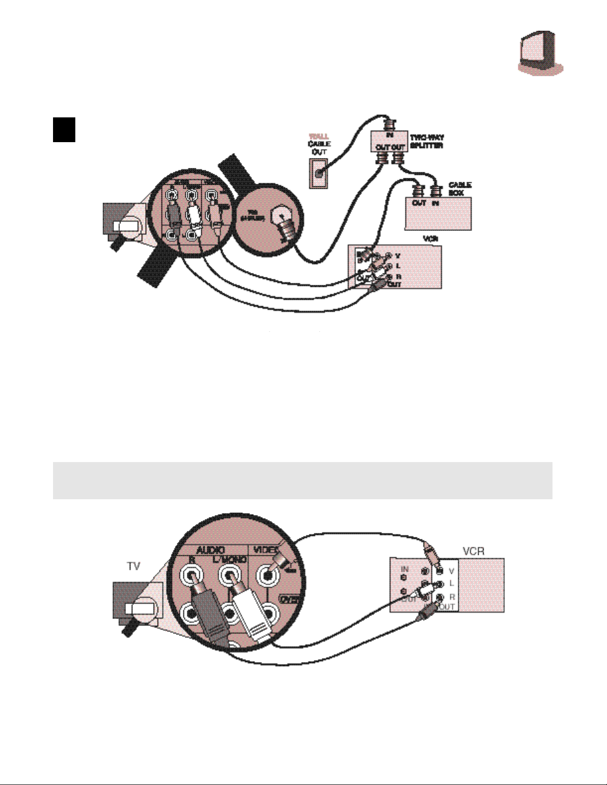
#3
CABLE & VCR CONNECTIONS CONTINUED
1) Connect Cable RF wire out from wall, in to splitter RF input.
2) Connect RF Out from splitter RF output, in to cable box RF input.
3) Connect RF wire Out from cable box RF output, in to VCR RF input.
4) Connect RF wire Out from splitter RF output, in to TV VHF/UHF input.
5) Connect yellow video cable out from VCR Video output, in to TV Video input jack.
6) Connect white audio cable out from VCR Left audio output, in to TV Left Audio input jack.
7) Connect red audio cable o u t f rom VCR Right Audio output, i nto TV Right Audio input jack.
❒ If your VCR is mono it has only one audio out jack, connect it to TV L/Mono input.
To get stereo sound from a hi-fi s t e reo VCR, you must connect it to the TV with Audio/Video cables.
To get the best picture quality from any VCR, you should connect it to the TV with Audio/Video cables.
1) Yellow video cable out from VCR, in to TV Video input jack.
2) White audio cable out from VCR Left Audio output, in to TV Left Audio input jack.
3) Red audio cable o u t f rom VCR RightAudio output, i nto TV Right Audio input jack.
NOTE: If your VCR is mono, it has only one audio out jack. Connect it to the TV L/Mono input.
AUDIO/VIDEO CONNECTIONS — STEREO

8 C O N N E C T I O N S
Play your home movies back through your TV by connecting your camcorder to the TV’s A/V I n p u t s .
1) White audio cable out from camcorder, in to TV Left Audio input jack.
2) Yellow video cable out from camcorder, in to TV Video input jack.
3) If you have a stereo model camcorder, connect the Red Audio cable out from the camcorder, in
to the TV Right Audio input jack.
TO CONNECT TO S-VHS ACCESSORIES:
Keep the audio connections the same as for a non-S-VHS VCR or camcorder (above), and use the
special S-VHS cable that came with the VCR or Camcorder.
1) S-VHS Plug out from VCR, in to TV’s S-Video input.
CONNECTING TO A CAMCORDER
CONNECTING TO AN EXTERNAL AMPLIFIER
1) White audio cable out from TV Left Audio output jack, in to Amplifier [Left] input.
2) Red audio cable out from TV Right Audio output jack, in to Amplifier [Right] input.
NOTE: A) Set the TV Speaker to OFF (page 21), switch the audio output to VARI (page21), and
adjust the sound with the TV remote’s VOLUME button.
C O N N E C T I O N S 9
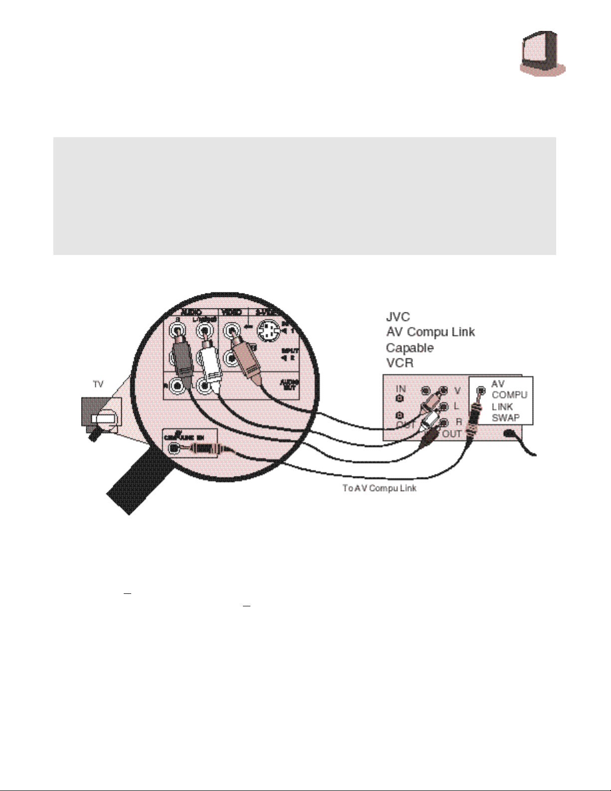
CONNECTING TO JVC AV COMPU LINK
CAPABLE COMPONENTS
AV Compu Link makes playing video tapes totally automatic. Simply insert a pre-recorded tape* into
the JVC brand VCR, and the VCR automatically turns on and starts playing. At the same time, the
VCR sends an AV Compu Link signal to the television telling it to turn on and switch to the correct
video input.
NOTE: The AV Compu Link cable should be included with the AV Compu Link capable accessory
you intend to connect. If it is not, contact an authorized JVC Service Center for Part # EWP 805-012.
NOTES:
A) The AV Compu Link cable has a male 3.5 mm (mono) mini plug on each end.
B) If your JVC brand VCR has A Code/B Code Remote Control Switching (see your VCR instructions),
using VCR
A Code will switch the TV to Video Input 1. If you use Input 1 for Video out from the
cable box, use Input 2 here. Using
B Code will switch the TV to Video Input 2.
C) To connect a JVC HiFi receiver or amplifier for a completely automated home theater, see the HiFi
receiver's instructions for detailed hookup diagrams.
* In order for the VCR to start playback automatically, the recording tabs must be removed from the
VHS tape. If the tab is in place, automatic switching starts when you push the VCR P
LAY
button.
** AV COMPULINK EX is compatible with the following 1998 receivers: RX-664V, RX-665V, RX-774V,
RX-884V, RX-1024V, and later receiver models.
 Loading...