


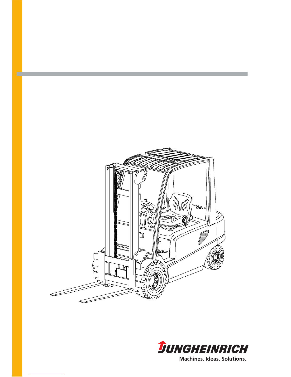
EFG-Vac 30
Jungheinrich EFG-Vac 30, EFG-Vac 25L, EFG-Vac 22, EFG-Vac 22-30, 25L Service Manual
...
Operating instructions
50116333
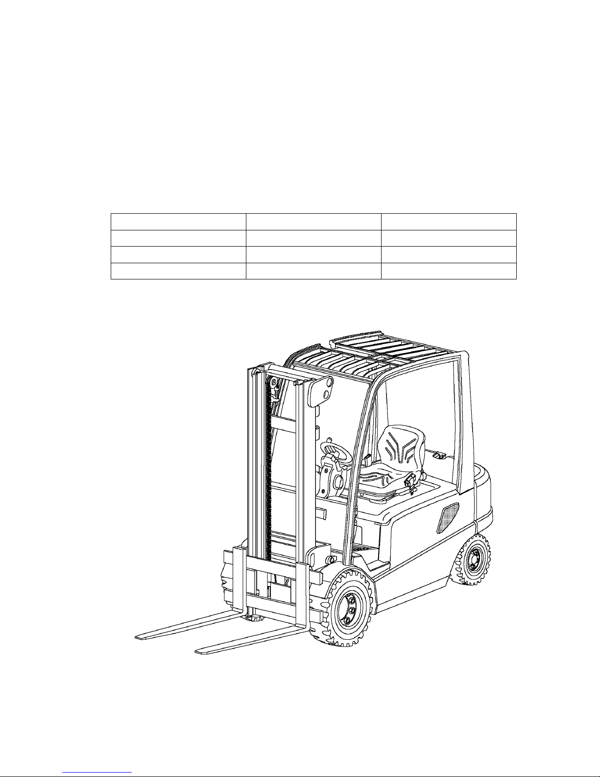
EFG-Vac 22-30 / 25L/S/SL
G
01.01-
12.03
Downloaded from www.Manualslib.com manuals search engine

0108.GB
Foreword
The present ORIGINAL OPERATING INSTRUCTIONS are designed to provide
sufficient instruction for the safe operation of the industrial truck. The information is
provided clearly and concisely. The chapters are arranged by letter. Each chapter
starts with page 1. The page identification consists of a chapter letter and a page
number.
For example: Page B 2 is the second page in chapter B.
The operating instructions detail different truck models. When operating and servicing
the truck, make sure that the instructions apply to your truck model.
Safety instructions and important explanations are indicated by the following
graphics:
f
Used before safety instructions which must be observed to avoid danger to
personnel.
m
Used before notices which must be observed to avoid material damage.
A
Used before notices and explanations.
t Used to indicate standard equipment.
o Used to indicate optional equipment.
Our trucks are subject to ongoing development. Jungheinrich reserves the right to
alter the design, equipment and technical features of the truck. No guarantee of
particular features of the truck should therefore be inferred from the present operating
instructions.
Copyright
Copyright of these operating instructions remains with JUNGHEINRICH AG.
Jungheinrich Aktiengesellschaft
Am Stadtrand 35
22047 Hamburg - GERMANY
Telephone: +49 (0) 40/6948-0
www.jungheinrich.com
Downloaded from www.Manualslib.com manuals search engine

0108.GB
0108.GB
Downloaded from www.Manualslib.com manuals search engine

I 1
5082973 - 50116333 GB
Table of contents
A Correct use and application of the truck
B Description of the truck
1 Design and application ........................................................................ B 1
2 Description of assembly groups and functions .................................... B 2
2.1 Truck ................................................................................................... B 3
3 Technical data - standard version ....................................................... B 4
3.1 Performance data ................................................................................ B 7
3.2 Weight (all weights in kg) .................................................................... B 8
3.3 Tyres ................................................................................................... B 8
3.4 Trailer loads ........................................................................................ B 8
3.5 EN standards ...................................................................................... B 9
3.6 Conditions for application .................................................................... B 9
4 Label positions and identification plates .............................................. B 10
4.1 Identification plate, truck ..................................................................... B 12
4.2 Truck load diagram ............................................................................. B 12
4.3 Fork arm load diagram (basic device) ................................................. B 13
4.4 Attachment load diagram .................................................................... B 13
C Transportation and commissioning
1 Transportation by crane ...................................................................... C 1
2 Commissioning .................................................................................... C 2
3 Moving the truck with the drive unit inoperative .................................. C 3
4 Towing the truck .................................................................................. C 3
D Battery - Servicing, recharging, replacement
1 Safety regulations governing the handling of lead-acid batteries ........ D 1
2 Battery types ....................................................................................... D 2
3 Opening the battery hood with support system (optional) ................... D 3
4 Exposing the battery ........................................................................... D 4
5 Charging the battery ............................................................................ D 5
6 Removing and installing the battery .................................................... D 6
7 Closing battery cover .......................................................................... D 7
8 Battery discharge indicator, exhaustive discharge protection
device, operating hour meter .............................................................. D 7
Downloaded from www.Manualslib.com manuals search engine

5082973 - 50116333 GB
I 2
E Operation
1 Safety regulations governing the operation of the fork lift truck .......... E 1
2 Description of Operating and Display Elements .................................. E 2
2.1 Switch at instrument panel .................................................................. E 4
2.2 Switches at operating panel ................................................................ E 4
2.3 Multifunction display ............................................................................ E 5
3 Starting up the truck ............................................................................ E 8
3.1 Checks and operations to be performed before starting daily work .... E 8
3.2 Adjusting the driver seat ...................................................................... E 8
3.3 Safety restraint belt ............................................................................. E 10
3.4 Automatic/Mechanical Support System (optional) .............................. E 12
3.5 Adjusting the steering column ............................................................. E 14
3.6 Providing operational readiness .......................................................... E 14
4 Operation of the fork lift truck .............................................................. E 15
4.1 Safety regulations applicable when operating the truck ...................... E 15
4.2 Driving ................................................................................................. E 16
4.3 Steering ............................................................................................... E 19
4.4 Braking ................................................................................................ E 19
4.5 Operating the lifting unit and attachments (MULTIPILOT) .................. E 21
4.6 Operating the lifting equipment and attachments (SOLOPILOT) ........ E 23
4.7 Picking up, transporting, and putting down load units ......................... E 24
4.8 Safe parking of the truck ..................................................................... E 27
4.9 Trailer towing ....................................................................................... E 28
4.10 Trailer loads ........................................................................................ E 28
5 Troubleshooting .................................................................................. E 29
Downloaded from www.Manualslib.com manuals search engine

I 3
5082973 - 50116333 GB
F Maintenance of the fork lift truck
1 Operational safety and environmental protection .................................F 1
2 Safety regulations applicable to truck maintenance .............................F 1
3 Servicing and inspection ......................................................................F 3
4 Maintenance checklist EFG-Vac ..........................................................F 4
5 Lubrication schedule EFG-Vac ............................................................F 6
5.1 Fuels, coolants and lubricants ..............................................................F 7
6 Description of servicing and maintenance operations ..........................F 8
6.1 Prepare truck for the servicing and maintenance operations ...............F 8
6.2 Check attachment of tyres ...................................................................F 8
6.3 Tyre pressure .......................................................................................F 8
6.4 Check hydraulic oil level .......................................................................F 9
6.5 Check transmission oil level .................................................................F 10
6.6 Draining oil ...........................................................................................F 10
6.7 Refilling oil ............................................................................................F 10
6.8 Changing the hydraulic filter .................................................................F 10
6.9 Changing the vacuum filter ..................................................................F 11
6.10 Check oil level for brake system ..........................................................F 11
6.11 Restrain safety belt service ..................................................................F 12
6.12 Checking the electric fuses ..................................................................F 13
6.13 Recommissioning after cleaning or maintenance operations ...............F 14
7 Decommissioning the fork lift truck ......................................................F 14
7.1 Operations to be performed prior to decommissioning ........................F 14
7.2 Measures to be taken during decommissioning ...................................F 14
7.3 Recommissioning the truck ..................................................................F 15
8 Safety checks to be performed at regular intervals and following any
untoward incidents (D: Accident prevention check according
to BGV D27) .........................................................................................F 15
Downloaded from www.Manualslib.com manuals search engine

5082973 - 50116333 GB
I 4
5082973 - 50116333 GB
I 4
Downloaded from www.Manualslib.com manuals search engine

A 1
5082973 - 50116333 GB
A Correct use and application of the truck
A
The „Guidelines for the Correct Use and Application of Industrial Trucks“ (VDMA) are
included in the scope of delivery for this truck. The guidelines are part of these
operating instructions and must always be heeded. National regulations are fully
applicable.
The fork-lift truck described in these operating instructions is a truck that is suitable
for lifting and transporting loads.
It must be used, operated and maintained according to the information in these
operating instructions. Any other uses are outside the design envelope and can lead
to injury to persons or damage to equipment and property. Above all, overloading
caused by excessively heavy or unbalanced loads must be avoided. The max.
admissible load to be picked up is indicated on the identification plate or load diagram
label shown on the truck. The operator must ensure that damaged and/or poorly
readable load diagrams are renewed. The fork-lift truck must not be operated in
spaces subject to fire or explosion hazards, or in spaces where corrosive or very
dusty atmospheres prevail.
Duties of the user: A „user“ within the meaning of these operating instructions is
defined as any natural or legal person who either uses the fork-lift truck himself, or on
whose behalf it is used. In special cases (e.g. leasing or renting), the user is
considered the person, who, in accordance with existing contractual agreements
between the owner and the user of the fork-lift truck, is charged with the observance
of the operating duties.
The user must ensure that the truck is not abused and only used within its design
limits and that all danger to life and limb of the operator, or third parties, is avoided.
In addition to this, it must be ensured that the relevant accident prevention regulations
and other safety-related provisions, as well as the operating, servicing and
maintenance guidelines, are observed. The user must also ensure that all persons
operating the truck have read and understood these operating instructions.
m
If these operating instructions are not observed the warranty becomes void. The
same applies if improper works are carried out at the device by the customer and/or
third parties without permission of our Customer Service.
Mounting of attachments: The mounting or installation of any attachments which
will interfere with, or supplement, the functions of the truck is permitted only after
written approval by the manufacturer has been obtained. If necessary, the approval
of local authorities has to be obtained.
Any approval obtained from local authorities does not, however, make the approval
by the manufacturer unnecessary.
Trailing and slipping loads: The truck may only be used for trailing or slipping loads
for which the truck has been approved.
Downloaded from www.Manualslib.com manuals search engine

5082973 - 50116333 GB
A 2
5082973 - 50116333 GB
A 2
Downloaded from www.Manualslib.com manuals search engine
B 1
5082973 - 50116333 GB
B Description of the truck
1 Design and application
EFG-Vac is an electric rider-controlled fork lift truck in four-wheel construction with
front drive which picks up, transports, and lifts its load outside the wheelbase. It is a
cantilevered counterbalance truck which can – due to its load lifting device being
located in front of the lift truck – unload lorries and deliver the load on ramps or in
racks unimpededly. It can be used to stack and transport DIN 15142 pallets,
DIN 15144 lattice box pallet, and other palletised loads.
Truck types and maximum carrying capacity:
*) The load diagrams attached to the trucks are binding for the carrying capacity
Type max. carrying capacity *) Load centre
EFG-Vac 22 2,200 kg 500 mm
EFG-Vac 25 2,500 kg 500 mm
EFG-Vac 30 3,000 kg 500 mm
Downloaded from www.Manualslib.com manuals search engine
5082973 - 50116333 GB
B 2
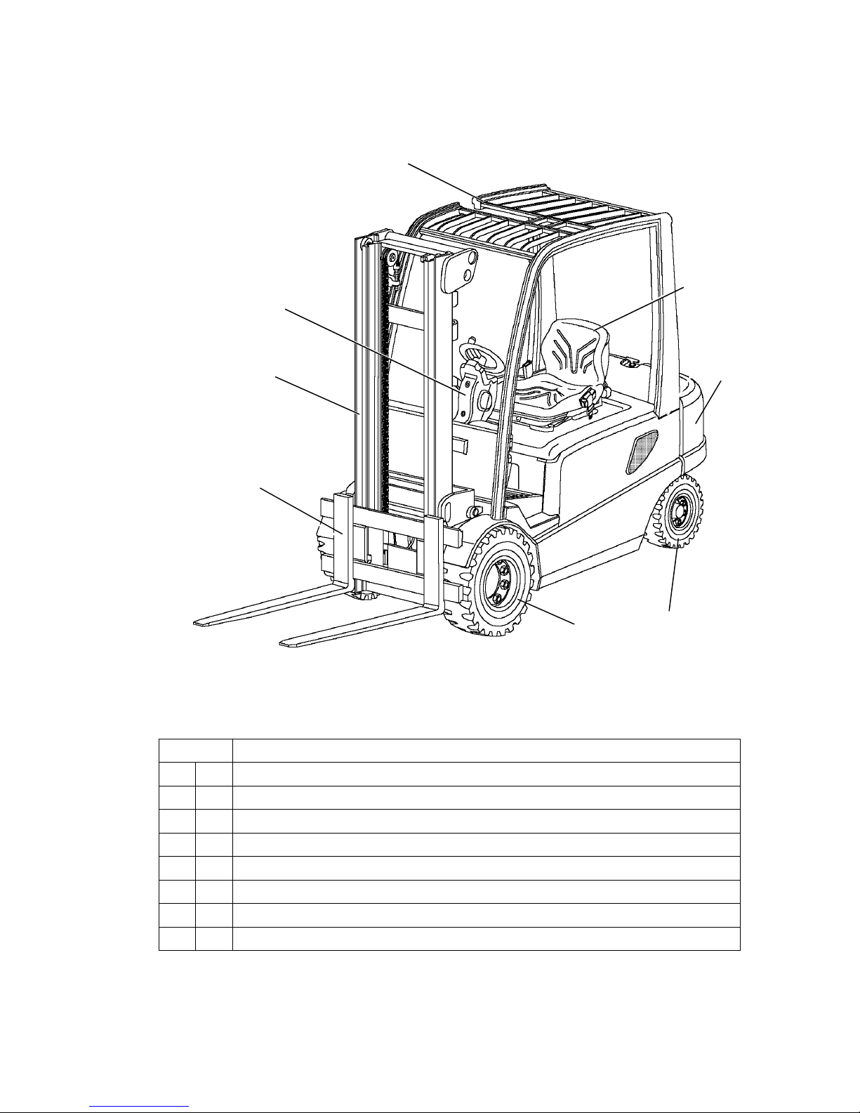
2 Description of assembly groups and functions
Item Designation
1 t Overhead guard
2 t Driver seat
3 t Counterweight
4 t Steering axle
5 t Drive axle
6 t Fork arm carriage
7 t Lifting mast
8 t Steering
1
2
3
4
5
6
7
8
5082973 - 50116333 GB
B 2
2 Description of assembly groups and functions
Item Designation
1 t Overhead guard
2 t Driver seat
3 t Counterweight
4 t Steering axle
5 t Drive axle
6 t Fork arm carriage
7 t Lifting mast
8 t Steering
1
2
3
4
5
6
7
8
Downloaded from www.Manualslib.com manuals search engine

B 3
5082973 - 50116333 GB
2.1 Truck
Steering (8): When a load is applied to the driver seat the steering is switched to
Standby. The steering unit runs at a preset idle speed. Depending on the steering
request the steering pump is increased and the travel speed is reduced depending on
the steering arc (“CurveControl”). The steering angle is indicated in the display.
Driver seat (2): The driver seat is a comfort seat and the steering column is
adjustable. There are storage places for documents or personal belongings of the
driver. The MULTI-PILOT combines all hydraulic functions and the travel direction
switch in one single lever. The overhead guard (1) is prepared for a cabin installation
and thus can be easily retrofitted.
Electric/electronic system: Sophisticated three-phase AC technology enables data
transfers with few cables only (CAN bus). Thus we achieve decreased susceptibility
to faults caused be broken cables as well as considerably faster fault isolation. The
complex TC system (Total Control) is designed for simply, safe, and flexible usage.
Depending on the load the driver can select from different operating programmes:
from high-performance to energy-saving. Convenient and very fast fault analysis and
programming can be performed via PC.
Drive and brake system: The front drive offers ideal traction to the drive wheels at
all times.
The hydraulically actuated oil-bath multi-disk brake used a service brake is practically
maintenance-free. The encapsulation in the transmission allows applications even in
aggressive environments. In addition, the lift truck is generatively braked via the travel
motor. Thus the energy consumption is minimised.
After approximately 15 sec standstill of the truck or 1 to 15 sec (adjustable) after the
driver seat is relieved the spring-loaded brake engages.
When actuating the accelerator the spring-loaded brake is automatically disengaged.
Hydraulic system: All functions must be executed sensitively, proportionally, and
simultaneously (only if this does not impair the safety). For higher efficiency a
hydraulic unit and a steering booster motor function separately from each other. The
micro pressure filter can be changed from the top (without spilling hydraulic oil).
Lifting mast (7): Our goal is optimising the view. The high-strength steel profiles are
narrow, which is especially notable in the three-stage lifting mast with its good view
to the fork arms. The same good results are achieved for the fork arm carriage.
The lifting mast as well as the fork arm carriage move on prelubricated and thus
maintenance-free cocked support rollers.
Downloaded from www.Manualslib.com manuals search engine

5082973 - 50116333 GB
B 4
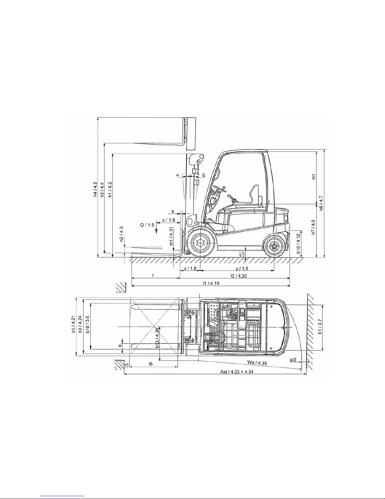
3 Technical data - standard version
1)
= +25 mm DZ mast
Designation
EFG-
Vac 22
EFG-
Vac 25
EFG-
Vac 25L
h1Height with mast retracted 2,200 2,200 2,200 mm
h
2
Free lift height 150 150 150 mm
h
3
Lift 3,100 3,100 3,100 mm
h
4
Height with mast extended 3,696 3,696 3,696 mm
h
6
Height above overhead guard 2,215 2,215 2215 mm
h
7
Seating height/standing height 1,060 1,060 1,060 mm
Seating room H1 1,105 1,105 1,105
h
10
Coupling height
390/
550
390/
550
390/
550
mm
L
1
Overall length including fork 3,428 3,428 3,572 mm
L2Length including fork back 2,278 2,278 2,422 mm
b1 Overall width 1,196 1,196 1,196 mm
b3 Width of fork arm carriage 1,120 1,120 1,120 mm
m1Ground clearance with load under lifting mast 110 110 110 mm
m2Ground clearance at centre of wheelbase 125 125 125 mm
Ast
Width of aisle
with pallets 800 × 1,200 lengthwise
3,875 3,875 4,025 mm
Ast
Width of aisle
with pallets 1,000 × 1,200 crossways
3,675 3,675 3,825 mm
W
a
Turning radius 2,050 2,050 2,200 mm
x Load distance 425
1)
425
1)
425
1)
mm
y Wheel-base 1,537 1,537 1,681 mm
5082973 - 50116333 GB
B 4
3 Technical data - standard version
1)
= +25 mm DZ mast
Designation
EFG-
Vac 22
EFG-
Vac 25
EFG-
Vac 25L
h1Height with mast retracted 2,200 2,200 2,200 mm
h
2
Free lift height 150 150 150 mm
h
3
Lift 3,100 3,100 3,100 mm
h
4
Height with mast extended 3,696 3,696 3,696 mm
h
6
Height above overhead guard 2,215 2,215 2215 mm
h
7
Seating height/standing height 1,060 1,060 1,060 mm
Seating room H1 1,105 1,105 1,105
h
10
Coupling height
390/
550
390/
550
390/
550
mm
L
1
Overall length including fork 3,428 3,428 3,572 mm
L2Length including fork back 2,278 2,278 2,422 mm
b1 Overall width 1,196 1,196 1,196 mm
b3 Width of fork arm carriage 1,120 1,120 1,120 mm
m1Ground clearance with load under lifting mast 110 110 110 mm
m2Ground clearance at centre of wheelbase 125 125 125 mm
Ast
Width of aisle
with pallets 800 × 1,200 lengthwise
3,875 3,875 4,025 mm
Ast
Width of aisle
with pallets 1,000 × 1,200 crossways
3,675 3,675 3,825 mm
W
a
Turning radius 2,050 2,050 2,200 mm
x Load distance 425
1)
425
1)
425
1)
mm
y Wheel-base 1,537 1,537 1,681 mm
Downloaded from www.Manualslib.com manuals search engine

B 5
5082973 - 50116333 GB
1)
= +25 mm DZ mast
Designation
EFG-
Vac 25S
EFG-Vac
25SL
EFG-
Vac 30
h1Height with mast retracted 2,200 2,200 2,200 mm
h
2
Free lift height 150 150 150 mm
h3Lift 3,100 3,100 3,100 mm
h4Height with lifting mast extended 3,696 3,696 3,806 mm
h
6
Height above overhead guard 2,215 2,215 2,215 mm
h7Seating height/standing height 1,060 1,060 1,060 mm
Seat clearanceH1 1,105 1,105 1,105
h
10
Coupling height 390/550 390/550 390/550 mm
L1Overall length including fork 3,428 3,572 3,577 mm
L2Overall length including fork back 2,278 2,422 2,427 mm
b1 Overall width 1,196 1,196 1,196 mm
b3 Width of fork arm carriage 1,120 1,120 1,120 mm
m
1
Ground clearance under lifting mast
with load
110 110 110 mm
m
2
Ground clearance at centre of wheelbase 125 125 125 mm
Ast
Width of aisle
with pallets 800 × 1,200 lengthwise
3,875 4,025 4,030 mm
Ast
Width of aisle
with pallets 1,000 × 1,200 crossways
3,675 3,825 3,830 mm
W
a
Turning radius 2,050 2,200 2,200 mm
x Load distance 425
1)
425
1)
430
1)
mm
y Wheel-base 1,537 1,681 1,681 mm
Downloaded from www.Manualslib.com manuals search engine
5082973 - 50116333 GB
B 6
5082973 - 50116333 GB
B 6
Downloaded from www.Manualslib.com manuals search engine

B 7
5082973 - 50116333 GB
3.1 Performance data
Designation
EFG-Vac
22
EFG-Vac
25
EFG-Vac
25L
Q Carrying capacity/load 2.2 2.5 2.5 t
c Load centre 500 500 500 mm
Travel speed with/without load 17/18 17/18 17/17 km/h
Lifting speed
with/without load
0.46/0.54 0.44/0.54 0.44/0.54 m/s
Lowering speed
with/without load
0.58/0.56 0.58/0.56 0.58/0.56 m/s
Negotiable gradient
with/without load S2 30 min.
10/15 8.5/14 7.5/13 %
Max. negotiable gradient
with/without load S2 5 min.
20/31 18/29 17/27 %
Acceleration time
with/without load for 10 m
4.2/3.9 4.3/4,0 4.4/4.1 s
Designation
EFG-
Vac 25S
EFG-Vac
25SL
EFG-Vac
30
Q Carrying capacity/load 2.5 2.5 3.0 t
c Load centre 500 500 500 mm
Travel speed with/without load 20/20 20/20 20/20 km/h
Lifting speed
with/without load
0.55/0.60 0.55/0.60 0.50/0.60 m/s
Lowering speed
with/without load
0.58/0.56 0.58/0.56 0.58/0.56 m/s
Negotiable gradient
with/without load S2 30 min.
12/19 11/17 10/17 %
Max. negotiable gradient
with/without load S2 5 min.
21/35 20/32 18/29 %
Acceleration time
with/without load for 10 m
4.1/3.7 4.1/3.7 4.2/3.8 s
Downloaded from www.Manualslib.com manuals search engine

5082973 - 50116333 GB
B 8
3.2 Weight (all weights in kg)
3.3 Tyres
3.4 Trailer loads
Designation
EFG-Vac
22
EFG-Vac
25
EFG-Vac
25L
Dead weight (incl. battery) 4,300 4,600 4,750 kg
Battery weight 1,558 1,558 1,872 kg
Load per axle with load front/rear 5,800/700 6,300/800 6,400/850 kg
Load per axle without load front/rear 2,300/2,000 2,300/2,300 2,530/2,220 kg
Designation
EFG-Vac
25 S
EFG-Vac
25 SL
EFG-Vac
30
Dead weight (incl. battery) 4,600 4,750 5,100 kg
Battery weight 1,558 1,872 1,872 kg
Load per axle with load front/rear 6,300/800 6,400/850 7,250/850 kg
Load per axle without load front/rear 2,300/2,300 2,530/2,220 2,600/2,500 kg
Designation
EFG-Vac
22
EFG-Vac
25
EFG-Vac
25L
Solid rubber tyres,
SE (= solid), air
Solid Solid Solid
Tyre size, front 23 x 9-10 23 x 9-10 23 x 9-10
Tyre size, rear 18 x 7-8 18 x 7-8 18 x 7-8
Number of wheels, front/rear
(x=driven)
2x / 2 2x / 2 2x / 2
b
10
Track, front 990 990 990 mm
b
11
Track, rear 920 920 920 mm
Designation
EFG-Vac
25S
EFG-Vac
25SL
EFG-Vac
30
Solid rubber tyres,
SE (= solid), air
Solid Solid Solid
Tyre size, front 23 x 9-10 23 x 9-10 23 x 10-12
Tyre size, rear 18 x 7-8 18 x 7-8 18 x 7-8
Number of wheels, front/rear
(x=driven)
2x / 2 2x / 2 2x / 2
b
10
Track, front 990 990 956 mm
b11Track, rear 920 920 920 mm
Max. permissible trailer
loads
EFG-Vac 22 EFG-Vac 25 EFG-Vac 25L
12,900 13,800 13,800 kg
EFG-Vac 25S EFG-Vac 25SL EFG-Vac 30
13,800 13,800 15,300 kg
Downloaded from www.Manualslib.com manuals search engine

B 9
5082973 - 50116333 GB
3.5 EN standards
Continuous sound pressure:
EFG-Vac 22/25/25L = 70 dB(A)
EFG-Vac 25S/25SL/30 = 71 dB(A)
according to EN 12053 as stipulated in ISO 4871
A
The continuous sound level is a value averaged according to standard regulations,
taking the sound pressure level into account when driving, lifting and idling. The
sound pressure level is measured at the ear.
Vibration: EFG-Vac 22-30 = aw,zS = 0.45 m/s
2
According to EN 13059
A
The swinging acceleration acting on the body in its operating position is, according to
standard regulations, the linear integrated, weighted acceleration in the vertical
plane. It is determined by driving over bumps with a constant speed.
Electromagnetic compatibility (EMC)
The manufacturer confirms compliance with the limit values for electromagnetic emission and interference immunity as well as testing of static electricity discharge according to EN 12895 and the references to other
standards contained therein.
A
Electrical or electronic components and their arrangement may only be modified after
written approval by the manufacturer has been obtained.
3.6 Conditions for application
Ambient temperature:
- during operation: -20°C to 40°C
A
Industrial trucks must be specially equipped and approved for continuous use in
environments with temperatures below 5°C or in cold stores respectively with
extreme temperatures or humidity changes.
B 9
5082973 - 50116333 GB
3.5 EN standards
Continuous sound pressure:
EFG-Vac 22/25/25L = 70 dB(A)
EFG-Vac 25S/25SL/30 = 71 dB(A)
according to EN 12053 as stipulated in ISO 4871
A
The continuous sound level is a value averaged according to standard regulations,
taking the sound pressure level into account when driving, lifting and idling. The
sound pressure level is measured at the ear.
Vibration: EFG-Vac 22-30 = aw,zS = 0.45 m/s
2
According to EN 13059
A
The swinging acceleration acting on the body in its operating position is, according to
standard regulations, the linear integrated, weighted acceleration in the vertical
plane. It is determined by driving over bumps with a constant speed.
Electromagnetic compatibility (EMC)
The manufacturer confirms compliance with the limit val-
ues for electromagnetic emission and interference immu-
nity as well as testing of static electricity discharge ac-
cording to EN 12895 and the references to other
standards contained therein.
A
Electrical or electronic components and their arrangement may only be modified after
written approval by the manufacturer has been obtained.
3.6 Conditions for application
Ambient temperature:
- during operation: -20°C to 40°C
A
Industrial trucks must be specially equipped and approved for continuous use in
environments with temperatures below 5°C or in cold stores respectively with
extreme temperatures or humidity changes.
Downloaded from www.Manualslib.com manuals search engine
5082973 - 50116333 GB
B 10
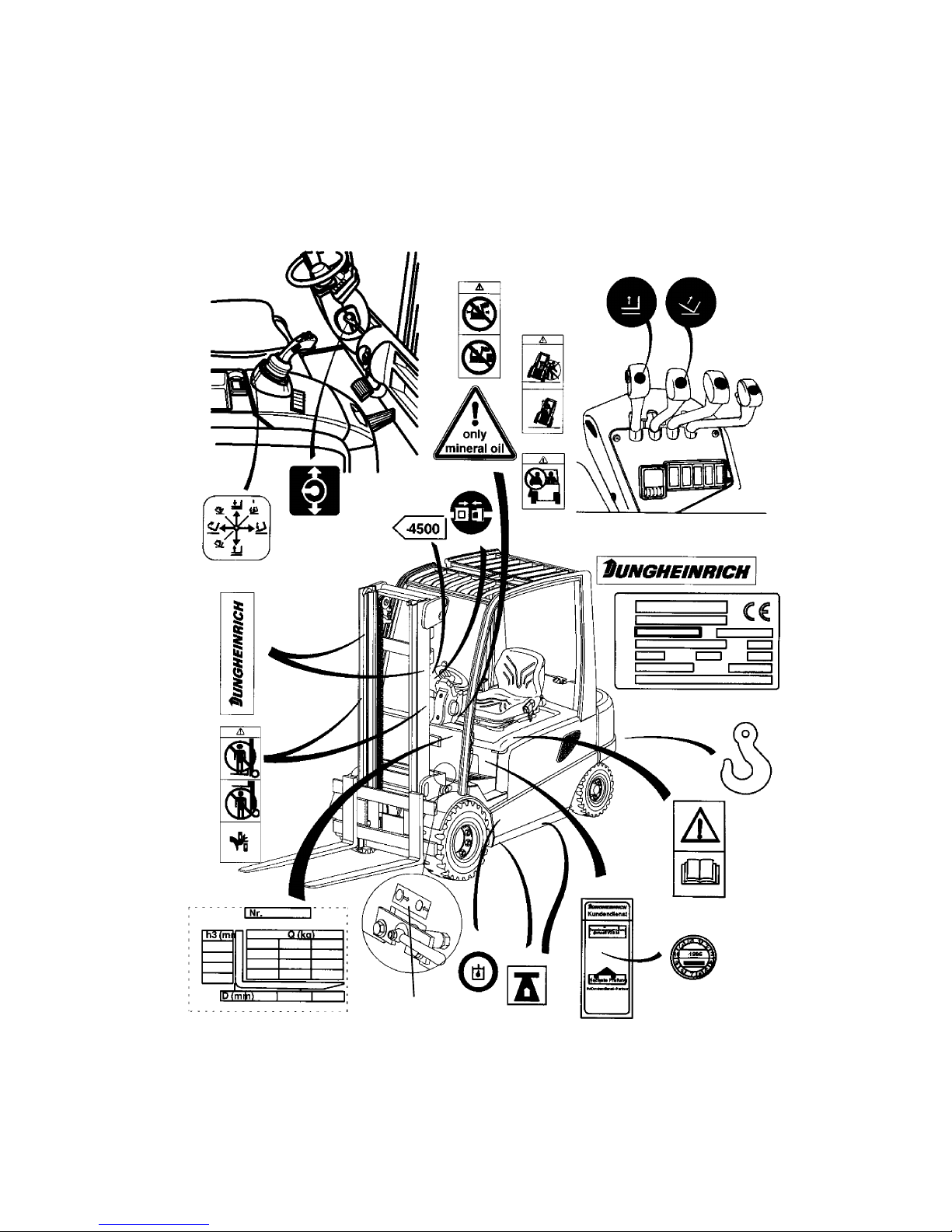
4 Label positions and identification plates
f
Warning and information labels such as load diagrams, sling points, and ID plates
must be readable at all times and must be renewed, if necessary.
2
3
4
1
5
6
7
8
9
10
11
12
13
20
21
18
17
16
15
21
19
14
4
5082973 - 50116333 GB
B 10
4 Label positions and identification plates
f
Warning and information labels such as load diagrams, sling points, and ID plates
must be readable at all times and must be renewed, if necessary.
2
3
4
1
5
6
7
8
9
10
11
12
13
20
21
18
17
16
15
21
19
14
4
Downloaded from www.Manualslib.com manuals search engine

B 11
5082973 - 50116333 GB
Item Designation
1 Label, sling points
2 Label, hydraulic functions (MULTI-PILOT)
3 Label, safety belt
4 Label, No passengers allowed
5 Label, observe operating instructions
6 Label, refill hydraulic oil
7 Label, capacity
8 Label, do not step on or under load, danger of crushing
9 Label, do not drive with elevated load, forward mast tilt with
elevated load prohibited
10 Label, warning when turning over
11 Label, lifting/lowering
12 Label, tilt forward/backward
13 Identification plate
14 Label, mineral oil
15 Label, spring-loaded brake
16 Label, lifting point
17 Accident prevention inspection label
18 Label, inspection plate
19 Label, lift limitation
20 Label, steering column adjustment
21 Label, Jungheinrich
Downloaded from www.Manualslib.com manuals search engine
5082973 - 50116333 GB
B 12
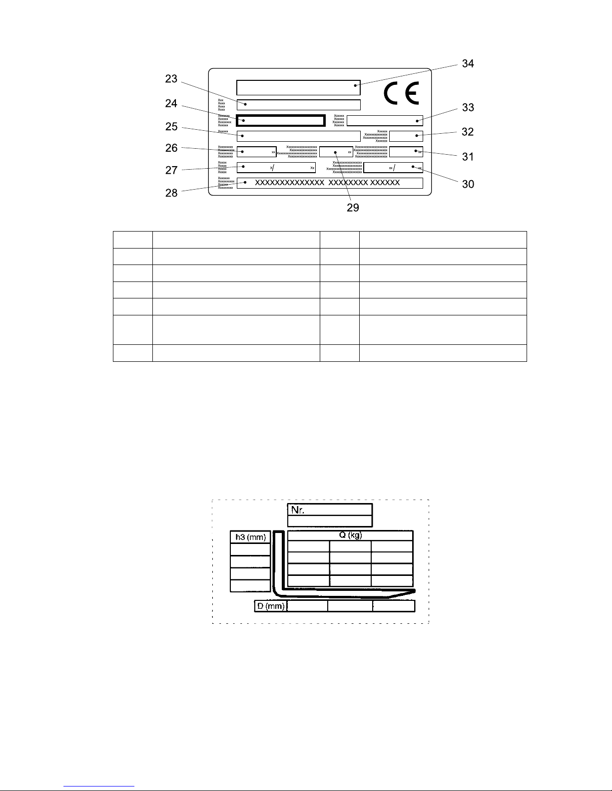
4.1 Identification plate, truck
A
In the event of queries relating to the truck or spare part orders, please state the serial
No. (24) of the truck.
4.2 Truck load diagram
The truck load diagram indicates the carrying capacity Q kg of the truck with the lifting
mast in vertical position. The table shows the maximum carrying capacity at a
standard load centre distance D (in mm) and the desired lifting height H (in mm).
Example for determining the maximum carrying capacity:
At a load centre distance of D = 600 mm and maximum lifting height H = 3,600 mm
the maximum carrying capacity Q = 1,105 kg.
Item Designation Item Designation
23 Type 29 Load centre distance in mm
24 Serial no. 30 Min./max. battery weight in kg
25 Order No. 31 Dead weight without battery in kg
26 Carrying capacity in kg 32 Year of manufacture
27 Battery: Voltage V
Ampere hours Ah
33 Type No.
28 Manufacturer 34 Manufacturer's logo
4,250
3,600
2,900
1,250 1,250
850
500
600 700
1,105
1,105
850
850
850
600
Example:
5082973 - 50116333 GB
B 12
4.1 Identification plate, truck
A
In the event of queries relating to the truck or spare part orders, please state the serial
No. (24) of the truck.
4.2 Truck load diagram
The truck load diagram indicates the carrying capacity Q kg of the truck with the lifting
mast in vertical position. The table shows the maximum carrying capacity at a
standard load centre distance D (in mm) and the desired lifting height H (in mm).
Example for determining the maximum carrying capacity:
At a load centre distance of D = 600 mm and maximum lifting height H = 3,600 mm
the maximum carrying capacity Q = 1,105 kg.
Item Designation Item Designation
23 Type 29 Load centre distance in mm
24 Serial no. 30 Min./max. battery weight in kg
25 Order No. 31 Dead weight without battery in kg
26 Carrying capacity in kg 32 Year of manufacture
27 Battery: Voltage V
Ampere hours Ah
33 Type No.
28 Manufacturer 34 Manufacturer's logo
4,250
3,600
2,900
1,250 1,250
850
500
600 700
1,105
1,105
850
850
850
600
Example:
Downloaded from www.Manualslib.com manuals search engine
B 13
5082973 - 50116333 GB
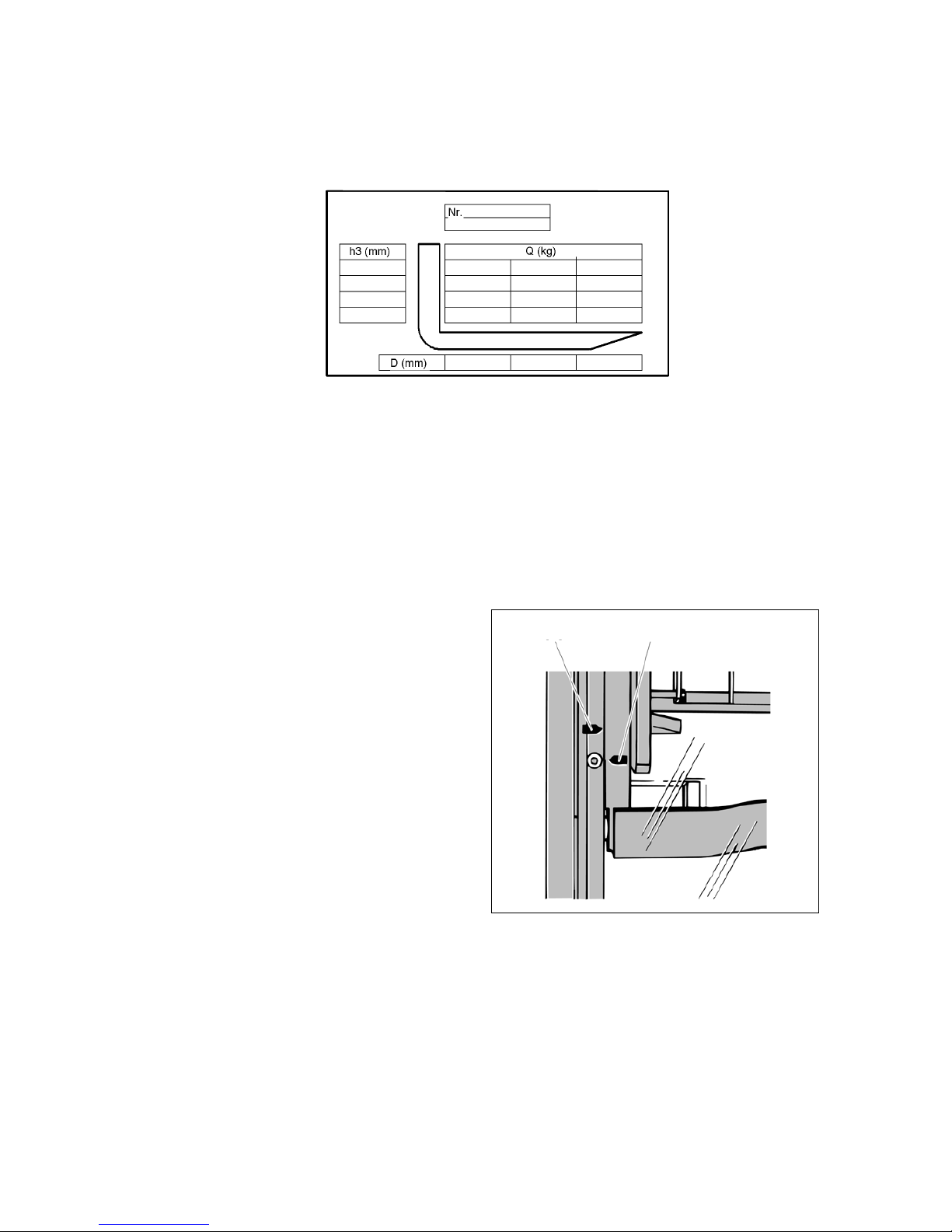
4.3 Fork arm load diagram (basic device)
The fork arm load diagram indicates the carrying capacity Q of the truck in kg. In the
diagram the maximum carrying capacity for different load centres D (in mm) is shown.
4.4 Attachment load diagram
The attachment load diagram indicates the carrying capacity Q of the truck in
connection with the respective attachment in kg. The attachment serial number
indicated in the load diagram must correspond to the ID plate of the attachment, since
the manufacturer must state the carrying capacity specially for each attachment. It is
indicated in the same way as the carrying capacity of the truck itself and must be
determined accordingly.
The arrow markings (46 and 47) at the
inner respectively outer mast indicate to
the driver that the lift limitations
prescribed in the load diagram have
been reached.
46 47
B 13
5082973 - 50116333 GB
4.3 Fork arm load diagram (basic device)
The fork arm load diagram indicates the carrying capacity Q of the truck in kg. In the
diagram the maximum carrying capacity for different load centres D (in mm) is shown.
4.4 Attachment load diagram
The attachment load diagram indicates the carrying capacity Q of the truck in
connection with the respective attachment in kg. The attachment serial number
indicated in the load diagram must correspond to the ID plate of the attachment, since
the manufacturer must state the carrying capacity specially for each attachment. It is
indicated in the same way as the carrying capacity of the truck itself and must be
determined accordingly.
The arrow markings (46 and 47) at the
inner respectively outer mast indicate to
the driver that the lift limitations
prescribed in the load diagram have
been reached.
46 47
Downloaded from www.Manualslib.com manuals search engine

5082973 - 50116333 GB
B 14
5082973 - 50116333 GB
B 14
Downloaded from www.Manualslib.com manuals search engine
C 1
5082973 - 50116333 GB
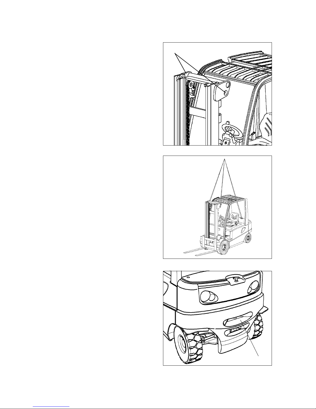
C Transportation and commissioning
1 Transportation by crane
m
Only lifting gear of adequate capacity
must be used
(loading weight = own weight + battery
weight; see identification plate of the
truck).
– Safe parking of the truck
(refer to chapter E)
– Fasten hoisting gear at lifting mast
crossbeam (1) and at trailer coupling
(2).
m
Transporting by crane is only provided
for transport for first commissioning.
For application conditions that require
frequent shipment (changing usage
locations) it is required to consult the
manufacturer.
m
Hoisting belts or chains may only be
hooked into the top lug of the
counterweight and the lugs of the end
crosshead (lifting mast).
The lifting mast must be fully tilted back.
The hoisting belt or chain at the mast
must have a minimum free length of
2m.
m
The crane hoisting gear must be
attached in such a way that it cannot
touch any attached components or the
overhead guard during lifting.
1
2
C 1
5082973 - 50116333 GB
C Transportation and commissioning
1 Transportation by crane
m
Only lifting gear of adequate capacity
must be used
(loading weight = own weight + battery
weight; see identification plate of the
truck).
– Safe parking of the truck
(refer to chapter E)
– Fasten hoisting gear at lifting mast
crossbeam (1) and at trailer coupling
(2).
m
Transporting by crane is only provided
for transport for first commissioning.
For application conditions that require
frequent shipment (changing usage
locations) it is required to consult the
manufacturer.
m
Hoisting belts or chains may only be
hooked into the top lug of the
counterweight and the lugs of the end
crosshead (lifting mast).
The lifting mast must be fully tilted back.
The hoisting belt or chain at the mast
must have a minimum free length of
2m.
m
The crane hoisting gear must be
attached in such a way that it cannot
touch any attached components or the
overhead guard during lifting.
1
2
Downloaded from www.Manualslib.com manuals search engine

5082973 - 50116333 GB
C 2
2 Commissioning
f
Commissioning and instructing drivers may only be performed by appropriately
trained personnel. If several trucks are delivered, care must be taken that only load
carrying units, lifting masts, and basic truck with identical serial numbers are
assembled.
m
The truck must only be operated on
battery current. Rectified alternate
current will damage the electronics.
Cables connected to the battery (trailing
cables) must be less than 6 meters in
length.
In order to prepare the truck for work
following delivery or transportation, the
following operations must be performed:
– Check equipment for completeness.
– Check battery connections and acid
level (refer to chapter D, section 6).
– Check tightening torque of wheel nuts
(refer to chapter F, section 6.3).
– Bring the truck into service as
prescribed
(refer to chapter E, section 3).
Downloaded from www.Manualslib.com manuals search engine
 Loading...