


Jøtul GF 300 DV
Allagash
Gas Heater
Installation and Operation Instructions
WARNING:
IF THE INFORMATION IN THESE INSTRUCTIONS ARE NOT FOLLOWED EXACTLY, A FIRE OR EXPLOSION MAY RESULT CAUSING PROPERTY DAMAGE, PERSONAL INJURY OR LOSS OF LIFE.
FOR YOUR SAFETY:
DO NOT STORE OR USE GASOLINE OR OTHER FLAMMABLE VAPORS AND LIQUIDS IN THE VICINITY OF THIS OR ANY OTHER APPLIANCE.
INSTALLATION:
INSTALLATION AND SERVICE MUST BE PERFORMED BY A QUALIFIED INSTALLER, SERVICE AGENCY OR LICENSED GAS SUPPLIER.
WHAT TO DO IF YOU SMELL GAS:
•DO NOT TRY TO LIGHT ANY APPLIANCE.
•DO NOT TOUCH ANY ELECTRICAL SWITCHES.
•DO NOT USE THE PHONE IN YOUR BUILDING. IMMEDIATELY CALL YOUR GAS SUPPLIER FROM A NEIGHBOR’S PHONE.
•FOLLOW YOUR GAS SUPPLIER’S INSTRUCTIONS.
•IF YOU CANNOT REACH YOUR GAS SUPPLIER, CALL THE FIRE DEPARTMENT.
AVERTISSEMENT:
ASSUREZ-VOUS DE BIEN SUIVRE LES INSTRUCTIONS DANS CETTE NOTICE POUR REDUIRE AU MINIMUM LE RISQUE D’INCENDIE OU POUR EVITER TOUT DOMMAGE MATERIEL, TOUTE BLESSURE OU MORTALIT’E.
NE PAS ENTREPOSER NI UTILISER D’ESSENCE NI OU LIQUIDES INFLAMMABLES DANS LE VOISINAGE DE CET APPAREIL OU DE TOUT AUTRE APPAREIL.
L’INSTALLATION LE SERVICE DOIVENT ETRE EXECUTES PAR UN INSTALLATEUR QUALIFIE, AGENCE DE SERVICE OU LE FOURNISSEUR DE GAZ.
QUE FAIRE SI VOUS SENTEZ UNE ODEUR DE GAZ.
•NE PAS TENTER D’ALLUMER L’APPAREIL
•NE TOUCHEZ A AUCUM NTERRUPTEUR.
•NE PAS VOUS SERVIR DES TELEPHONES SE TROUVANT DANS LE BATIMENT OU VOUS VOUS TROUVEZ.
•APPELEZ IMMEDIATEMENT VOTRE FOURNISSEUR DE GAZ CHEZ UN VOISIN. SUIVEZ LES INSTRUCTIONS DU FOURNISSEUR.
•SI VOUS NE POUVEZ REJOINDRE LE FOURNISSEUR DE GAZ, APPELEZ LE SERVICE DES INCENDIES.
1

Welcome to Jøtul...
Congratulations on the purchase of your new
Jøtul GF 300 DV Allagash Gas Heater.
We at Jøtul are glad you’ve made the decision to warm your hearth with a Jøtul product.
Your new GF 300 DV Allagash exemplifies our experience gained over 150 years as the world’s largest manufacturer of solid fuel burning appliances. We’ve been making fine quality cast iron wood and coal stoves and fireplaces continuously since 1853.
The GF 300 DV Allagash combines advanced gas technology with the warm, traditional elements of cast iron. With proper care and use, your Jøtul stove will provide you with many years of safe, dependable and satisfying service.
The Jøtul GF 300 DV Allagash is a direct vented gas heater designed and approved for installation into a variety of configurations where close clearance to combustible material is required. Please take a few minutes to familiarize yourself with this manual and the features of your new Jøtul stove.
2
Table of Contents |
|
|
Service Tools .............................................. |
|
3 |
Specifications ........................................... |
|
4 |
General Information ............................... |
|
5 |
Safety Information .................................. |
|
6 |
Installation Requirements |
|
|
Location ................................................. |
|
6 |
Hearth Protection .............................. |
|
6 |
Clearances ............................................ |
|
7 |
Mantel & Trim ..................................... |
|
7 |
Alcove..................................................... |
|
7 |
Vent Requirements ................................. |
|
8 |
Adding Restriction.............................. |
|
8 |
Vertical Termination .......................... |
|
9 |
Co-linear Termination .................. |
|
12 |
Coaxial Chimney Conversion..... |
13 |
|
Horizontal Termination................... |
|
14 |
Vent Terminal Clearances |
............... |
15 |
Mobile Home Installation ................... |
|
16 |
Fuel Conversion ...................................... |
|
16 |
Gas Connection ...................................... |
|
18 |
Gas Pressure............................................ |
|
19 |
High Altitude Adjustment .................. |
|
19 |
Air Shutter Adjustment ....................... |
|
20 |
Wall Thermostat .................................... |
|
20 |
Remote Control ...................................... |
|
20 |
Log Set Installation ............................... |
|
21 |
System Check.......................................... |
|
22 |
Operation ................................................. |
|
23 |
Maintenance ........................................... |
|
24 |
Glass Replacement ............................ |
|
24 |
Optional Blower Installation .............. |
25 |
|
Optional Brick Kit Installation ........... |
27 |
|
Illustrated Parts Breakdown |
............... |
28 |
Replacement Parts List......................... |
|
29 |
Lighting Instructions ............ |
Back Cover |
|
THIS PRODUCT MUST BE INSTALLED
BY A LICENSED PLUMBER OR
GAS-FITTER WHEN INSTALLED IN THE COMMONWEALTH OF MASSACHUSETTS.
Jøtul GF 300 DV
Direct Vent Gas Heater
Manufactured and Distributed by:
Jøtul A.S.A.
Fredrikstad, Norway
Jøtul North America
Portland, Maine
Test Standards
This appliance complies with National Safety standards and is tested and listed by Intertek Testing Services of Middleton,
Wisconsin to ANSI Z21.88-2002•CSA 2.33-M02 and CAN/CGA 2.17--M91, CSA P.4.-01.2 for Canada.
DO NOT ATTEMPT TO ALTER OR MODIFY THE CONSTRUCTION OF THE APPLIANCE OR ITS COMPONENTS. ANY MODIFICATION OR ALTERATION WILL VOID THE WARRANTY, CERTIFICATION AND LISTING OF THIS APPLIANCE.
www.nficertified.org
We at Jøtul North America are dedicated to manufacturing the finest quality hearth products you can be assured will give you many years of safe, dependable service.
To ensure your confidence, we recommend that whenever possible, our products be installed and serviced by professionals who are certified by the National Fireplace Institute (NFI) or, in Canada, by
Wood Energy Technical Training (WETT).
3
GF 300 DV Specifications
Input Rates
Natural Gas
26,000 BTU/hr. maximum input
14,000 BTU/hr. minimum input
Propane
26,000 BTU/hr. maximum input
14,000 BTU/hr. minimum input
Inlet Pressure: |
MIN |
MAX |
Natural Gas: |
5.0 WC (1.24 kPa) |
7.0 WC (1.74 kPa) |
Propane: |
12.0 WC (2.99 kPa) |
14.9 WC (3.71 kPa) |
Manifold Pressure: MIN |
MAX |
|
Natural Gas: |
1.2 WC (.30 kPa) |
3.8 WC (.95 kPa) |
Propane: |
2.9 WC (.722 kPa) |
11.0 WC (2.74 kPa) |
Piezo Ignitor / Standing Pilot
Suggested Tools for
Installation and Service
•External regulator (for Propane only)
•Piping which complies with local code
•Manual shutoff valve (T-Handle in Massachusetts)
•Sediment trap - if required by code
•Tee joint
•Pipe wrench
•Pipe sealant
•10 mm open end wrench
•1/2”, 7/16” open end wrench or deep socket
•Phillips head screwdriver
•Flat head screwdriver
•1/4” nut driver
•4 mm allen wrench
•Gloves
•Safety glasses
•Torx T20 screwdriver
•Leak test solution
•Reciprocating Saw
•Power Drill
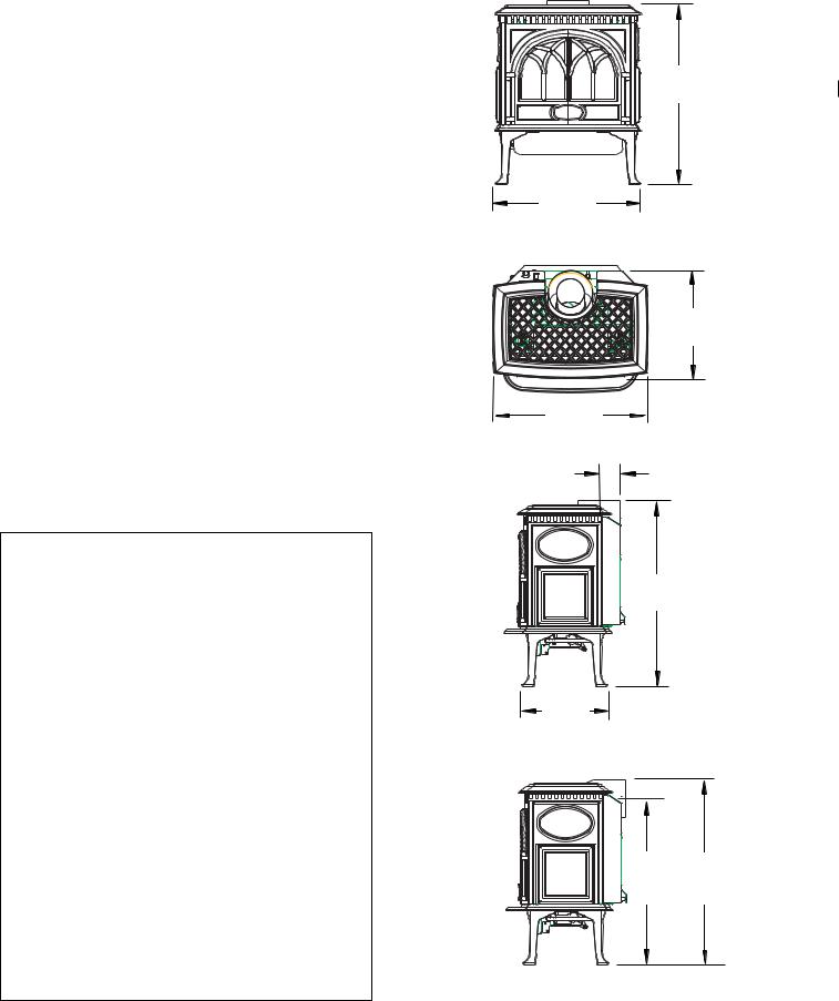
27 1/2”
698 mm
22 1/4”
565 mm
15 1/4”
500 mm
22 1/2”
572 mm
C
L
3 1/4”
83 mm
28 1/2”
724 mm
13” 330 mm
C
L
25 |
” |
28 |
” |
635 mm |
711 |
mm |
|
4
General Information
THIS HEATER MUST BE INSTALLED AND MAINTAINED BY A QUALIFIED SERVICE AGENCY.
The installation and repair of this appliance must be done by a qualified service person. Failure to properly install and maintain this heater could result in an unsafe or hazardous installation, which may result in a fire, explosion, property damage, personal injury or loss of life.
This appliance should be inspected before use and at least annually. More frequent cleaning may be required due to excessive lint from carpeting, bedding material, etc. It is imperative that control compartments, burners, and circulating air passageways of the appliance be kept clean.
THIS APPLIANCE MUST NOT BE CONNECTED TO A CHIMNEY OR FLUE SERVING ANY OTHER APPLIANCE.
The installation must conform to local codes. Your local Jøtul dealer can assist you in determining what is required in your area for a safe and legal installation. Some areas require a permit to install a gas burning appliance. Always consult your local building inspector, or authority having jurisdiction, to determine what regulations apply in your area.
CODE COMPLIANCE : Your local officials have final authority in determining if a proposed installation is acceptable. Any requirement that is requested by the local authority having jurisdiction, that is not specifically addressed in this manual, defaults to local code. In the absence of local codes, the installation requirements must comply with the current edition of National codes. In the U.S., these requirements are established in the National Fuel Code, ANSI Z223.1.(NFPA 54) current edition. In Canada, the codes have been established in CAN/CGA B149 Fuel Installation Code, current edition..
Installer l’appareil selon les codes ou reglements locaux, ou, en l’absence de tels reglements, selon les Codes d’installation CAN/CGA-B149.
DO NOT OPERATE THIS STOVE IF ANY PART HAS BEEN UNDER WATER. Call a qualified service technician to inspect the heater and to replace any part of the control system and any gas control which may have been under water.
Ne pas se servir de cet appareil s’il a ete’ plonge dans l’eau, completement ou en partie. Appeler un technicien qualifie pour inspecter l’appareil et remplacer toute partie du syste’me de controle et toute commande qui ont ete plonges dans l’eau.
Glass Panel
Do not operate this appliance with the glass front removed, cracked, or broken. Replacement of the glass should be done by a licensed or qualified service person. Only remove glass for routine service. Always handle glass carefully.
Unpacking your stove
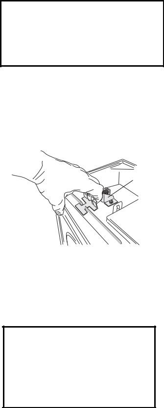
1.Remove the Top Plate of the stove by simply lifting it straight off of the stove body.
2.To open the firebox, disengage the two Glass Frame Latches located on top of the firebox. Pull each handle forward to clear the latch from the notch in the frame.
Glass Frame
Latch
3.Familiarize yourself with the installation requirements specified in this manual, before beginning the installation.
Hardware Bag Contents
•Fuel Conversion Kit - LP................................ 155372
•Ember Bag , 4 oz. ............................................ 220702
THIS FIREPLACE IS SHIPPED FROM THE FACTORY FOR USE WITH NATURAL GAS ONLY. IF USE WITH PROPANE IS DESIRED, THE APPLIANCE MUST FIRST BE CONVERTED USING THE FUEL CONVERSION KIT PROVIDED, #155372. CONVERSION SHOULD BE MADE BEFORE THE APPLIANCE IS INSTALLED. SEE PG. 17.
5
Safety Information
During normal operation, the GF 300 DV gas stove will reach high surface temperatures. Therefore:
Due to the high operating temperatures, this appliance should be located out of traffic areas and away from furniture and draperies.
Children and adults should be alerted to the hazards of high surface temperatures and should stay away to avoid burns and/or clothing ignition.
Young children should be supervised while they are in the same room as the GF 300 DV gas stove.
Clothing or other flammable materials should not be placed ON or NEAR the GF 300 DV gas stove. Surveiller les enfants. Garder les vetements, les meubles, l’essence ou autres liquides a vapeur inflammables loin de l’appareil.
NEVER store or use gasoline or any other flammable vapors or liquids in the vicinity of the GF 300 DV gas stove.
Never burn any other materials in your GF 300 DV Allagash gas stove, it is strictly designed for use with natural gas or propane fuel ONLY.
· Any safety screen, glass or guard removed for servicing the appliance must be replaced prior to operating the appliance.
Location
In selecting a location for the stove, consider the following points:
1)Heat distribution
2)Vent termination requirements
3)Gas supply line routing
4)Traffic areas, furniture, draperies, etc.
The GF 300 DV may be located on or near conventional construction materials, however, proper clearance to combustibles must be maintained in order to provide adequate air circulation around the appliance. Also, it is important to provide adequate access around the stove for servicing and proper operation.
The clearance and hearth specifications listed in this manual are the minimum requirements for combustible material. A combustible material is anything that can burn (i.e. sheet rock, wall paper, wood, fabrics etc.). These surfaces are not limited to those that are visible and also include materials that may be located behind noncombustibles.
If you are not sure of the combustible nature of a material, consult your local fire officials. Remember, “Fire Resistant” materials are considered combustible: they are difficult to ignite, but will burn. Also, “fire-rated” sheet rock is considered combustible.
Hearth Requirements
The GF 300 DV gas stove CANNOT be installed directly on carpeting, vinyl, linoleum or Pergo®.
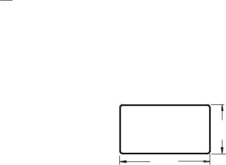
If this appliance will be installed on any combustible material OTHER THAN WOOD, a floor pad must be installed that is either metal or wood, or a listed hearth pad. This floor protection must extend the full width and depth of the appliance. It is not necessary to remove carpeting, vinyl or linoleum from underneath the floor protection. See fig. 1.
Figure 1. Minimum Hearth Protection.
14” (356 mm)
24” (686 mm)
6
Stove and Vent Clearance
Requirements
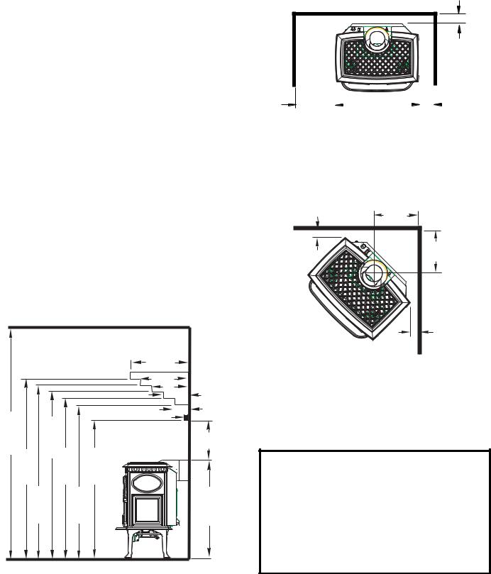
Minimum Clearances from the Stove to Combustibles: See figs. 2-4.
Rear: |
2” (51 mm) |
|
Ceiling: |
33” (838 mm) |
|
Corner: |
2” |
(51 mm) |
Right Side: |
3” |
(76 mm) |
Left Side: |
10” (254 mm) - for access to Lighting Instruction plate |
|
Minimum Clearances from the Vent Pipe to Combustibles:
Horizontal Run: |
|
|
Off the top of the pipe 2” |
(50 mm) |
|
Off the sides and bottom 1” |
(25 mm) |
|
Vertical Run: |
|
|
All sides |
1” (25 mm) |
|
Minimum Ceiling or Alcove Height
|
|
|
Max. Mantel Depth |
|
|
|
|
12.5” |
|
|
|
|
10.25” |
|
|
|
|
8” |
|
|
|
|
5.75” |
|
|
|
|
Min. Mantel Depth |
3.5” |
61” 1550mm |
551/2” 1410mm |
Max. Top Trim Depth = 1” |
|
|
|
18 1/2” |
|||
|
|
|
|
(419 mm) |
|
58 1/2” 1486 mm |
54” 1372 mm |
46 1/2” 1182 mm |
|
|
57” 1449 mm |
52 1/2” 1334 mm |
|
28” 711 mm |
Figure 2. Mantel and Trim Clearance specifications. Subtract 2 1/4” with Short Legs.
2” (51 mm)
To Rear Wall
10” * |
|
|
|
|
|
|
|
|
3” |
|
|
|
|
|
|
|
|
||
(254 mm) |
|
|
|
|
|
|
|
|
(76mm) |
|
|
|
|
|
|
|
|
||
Left Side |
|
|
|
Right Side |
|||||
* Allow 10” on left side of the appliance for complete access to the lighting instructions and control valve.
Figure 3. Parallel Installation Clearances.
|
11” |
|
280 mm |
2” |
11” |
51 mm |
280 mm |
|
2” |
|
51 mm |
Figure 4. Vent adaptor centerline at minimum clearance to corner walls.
Alcove Installation
Maximum Alcove Depth: |
24” (610 mm) |
Minimum Alcove Width: |
36 3/4” (934 mm) |
Minimum Ceiling Height: |
61” (1549 mm) |
With Short Legs (6”): |
58 3/4 (1486 mm) |
7
Venting Requirements
The Jøtul GF 300 DV gas stove may be installed with a vertical or horizontal termination and must conform to the configuration requirements described below.
This appliance is approved for use with vent systems from the following manufacturers:
•Simpson Dura-Vent GS
•Amerivent Corporation
•Security Vent Ltd.
•Selkirk Metalbestos
Use parts of one manufacturer only - DO NOT MIX VENT COMPONENTS FROM DIFFERENT MANUFACTURERS IN THE SAME SYSTEM.
Installation of any components not manufactured or approved by Jøtul or failure to meet all clearance requirements will void all warranties and could result in property damage, bodily injury, or serious fire.
The approved vent configurations described in this manual are derived from extensive testing under controlled laboratory conditions. Gas appliance performance can be negatively affected by variables present in the installation environment, i.e: atmospheric pressure, strong prevailing winds, adjacent structures and trees, snow accumulation, etc. These conditions should be taken into consideration by the installer and stove owner when planning the vent system design.
IMPORTANT
•JOINT SEALING REQUIREMENT: APPLY A 1/8” BEAD OF HIGH-TEMPERATURE (750°F) SEALANT TO THE MALE SECTION OF THE INNER VENT
PIPE. THE CEMENT SHOULD FORM A SEAL BETWEEN THE INNER AND OUTER PIPES.
•NEVER MODIFY ANY VENTING COMPONENT, OR USE
ANY DAMAGED VENTING |
SEALANT |
|
PRODUCT.
• THE GAS APPLIANCE AND VENT SYSTEM MUST BE
VENTED DIRECTLY TO THE |
|
|
OUTSIDE OF THE BUILDING |
|
|
AND NEVER ATTACHED TO A |
Figure 5. |
|
CHIMNEY SERVING A SOLID |
||
|
||
FUEL OR GAS BURNING |
|
|
APPLIANCE. EACH DIRECT VENT GAS APPLIANCE MUST |
||
HAVE ITS OWN SEPARATE VENT SYSTEM. COMMON |
||
VENT SYSTEMS ARE PROHIBITED. |
|
|
• IF VENTING SYSTEM IS DISASSEMBLED FOR ANY REASON, REINSTALL PER THE INSTRUCTIONS PROVIDED FOR THE INITIAL INSTALLATION.
Vent Restriction
The GF 300 DV is equipped with an Exhaust Restrictor Plate which enables you to regulate the flow of exhaust gas. The plate prevents overly strong draft that can cause poor combustion and weak flame picture. Follow the guidelines below, and on the following pages, to determine the correct restrictor plate setting for your particular installation configuration.
Exhaust Restrictor
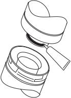
The Exhaust Restrictor is an adjustable shutter located at the top right side of the firebox. It is adjusted by moving a pivot pin into one of four positions. It is set in the FULLY OPEN (D) position at the factory. See Fig. 7. The four positions correlate to the termination zones (A,B,C,D) diagramed in figures 9-12. Consult these Vent Window diagrams on pages 10-11 to determine the setting you should use.
Additional restriction may be needed depending the overall vent height. If necessary, use Simpson Dura-Vent Restrictor Disk #929.
Adjusting Exhaust Restrictor Plate:
1.Use the Vent Window diagrams to determine which setting position to use.
2.Remove the Top Plate.
3.Locate the pivot pin at the right side of the firebox top. Use a 7 mm or 9/32 nut driver to loosen the nut on the pivot pin and then push the pin to the left to disengage it from the current factory-set position. Move the pin forward and into the slot appropriate for your specific vent configuration. See figs. 6 and 7.
4.Tighten the lock nut and replace the Top Plate.
8
|
D |
|
B |
C |
|
A |
||
|
Figure 6. Exhaust restrictor positions - viewed from front with top plate removed.
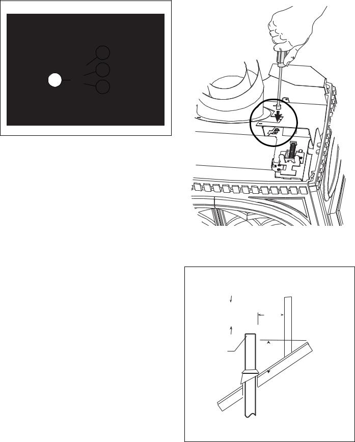
Vertical Vent Termination
The Jøtul GF 300 DV can be vertically vented through a ceiling or to a roof termination with the following guidelines:
The termination should fall within the shaded areas of the grids depicted in the Vent Window diagrams on pages 10 - 11.
Maximum Vertical run should not exceed 35 ft. (10.66 m).
Minimum Vertical run must be at least 8 ft. (2.43 m).
Max. Colinear Horizontal run is 2 ft. (61 cm).
Vent Terminus Clearance: In no case shall any discharge opening on the cap be less than 18 in. (610 mm) horizontally from the roof surface.
Steep roofs, nearby trees, and predominantly windy conditions can contribute to poor draft and/or promote down-draft occurances. Increasing the height of the vent may alleviate these conditions.
Use Wall Straps to support an offset pipe run at three feet intervals to avoid excessive stress on the offsets.
Elbows: Four 45°, or two 90° elbows may be used. Do not include the 45° elbow attached to the stove. Whenever possible use 45° elbows instead of 90° elbows as they are less restrictive to exhaust gas and intake air flow.
A firestop is required at every floor. The opening should be framed to 10" X 10" inside dimension.
Any venting that is exposed above the first floor, regardless of attic space or living space, must be enclosed. Always maintain the required 1" clearance from all sides of the vertical vent system.
See Fig. 6
Detail
Figure 7. Use a nut driver to change the Exhaust Restrictor setting.
|
|
|
|
Horizontal Overhang |
all |
|||||||||||
|
|
|
|
|
|
|
|
|
|
|
|
|
|
|
|
|
18”. |
|
|
|
18”. |
W |
|||||||||||
|
|
|
Vertical |
|||||||||||||
min. |
|
|
|
|
|
|
|
|
|
|
||||||
|
|
|
min. |
|||||||||||||
|
|
|
|
|||||||||||||
|
|
|
|
|
|
|
|
|
|
|
|
|
|
|
|
Lowest Discharge |
|
|
|
|
|
|
|
|
|
|
|
|
|
|
|
|
|
|
|
|
|
|
|
|
|
|
|
|
|
|
|
|
|
Opening |
Termination |
|
|
|
|
|
|
|
|
|
|
||||||
|
|
|
|
|
|
|
|
|
|
|
||||||
Cap |
|
|
|
|
|
|
|
|
|
|
|
|||||
|
18” min. |
|
||||||||||||||
|
|
|
|
|
|
|
|
|||||||||
|
|
|
|
|
|
|
|
|
|
|
|
|
|
|
|
|
|
|
|
|
|
|
|
|
|
|
|
|
|
|
|
|
|
|
|
|
|
|
|
|
|
|
|
|
|
|
|
|
|
|
|
|
|
|
|
|
|
|
|
|
|
|
|
|
|
|
|
Figure 8. Vertical vent termination height above roof.
9

Vent Windows for Natural Gas |
|
|
|
|||||
|
35 Ft. |
|
|
|
|
|
COLINEAR VENT |
|
(10.67 m) |
|
|
|
|
|
|||
|
|
|
|
|
|
|
|
35 Ft. |
|
|
|
|
COAXIAL VENT |
|
|
(10.67 m) |
|
|
|
|
|
|
|
|
||
|
30 Ft. |
|
|
|
|
|
|
|
|
(9.14 m) |
|
|
|
|
|
RUN |
|
|
|
|
|
Up to four 45° or |
|
|
||
RUN |
|
|
|
|
VERTICAL |
|
||
25 Ft. |
|
|
two 90° elbows |
|
|
|||
|
|
|
|
|
|
|||
|
|
|
permitted in |
|
|
|
||
|
(7.62 m) |
|
|
|
|
|
||
|
|
|
addition to the |
|
|
|
||
|
A |
|
|
|
|
25 Ft. |
||
|
|
|
starter elbow. |
|
|
(7.62 m) |
||
VERTICAL |
|
|
|
|
|
|||
20 Ft. |
A |
|
|
|
|
|
|
|
|
|
|
|
|
|
|
||
|
(6.10 m) |
|
|
|
|
|
|
B |
|
|
|
|
|
|
|
|
|
|
15 Ft. |
|
B |
|
|
|
|
|
|
(4.57 m) |
|
|
|
|
|
|
|
|
12 Ft. |
|
|
C |
|
|
|
|
|
(3.65 m) |
|
|
|
|
|
|
|
|
B |
|
|
|
D |
|
|
Minimum |
|
8 Ft. |
Min. Vertical |
|
|
|
|
Vertical |
|
|
Termination |
|
|
|
|
Termination |
||
|
(2.43 m) |
|
|
|
|
|
|
8 Ft. |
|
|
|
|
|
|
|
|
(2.43 m) |
|
5 Ft. |
|
|
|
|
|
|
|
|
(1.52 m) |
|
|
|
|
|
|
|
|
Min. Rise |
|
|
|
|
|
|
45° |
|
2 Ft. |
|
|
|
|
|
Elbow |
|
|
(.60 m) |
|
|
|
|
|
|
Up |
|
|
5 Ft. |
10 Ft. |
15 Ft. |
20 Ft. |
27 Ft. |
|
2 Ft. |
|
|
(1.52 m) |
(3.05 m) |
(4.57 m) |
(6.09 m) |
(8.22m) |
|
(16 cm) |
HORIZONTAL RUN |
|
HORIZONTAL RUN |
|
• ALL VENTING MUST TERMINATE (END) WITHIN ONE OF |
|
|
|
THE SHADED AREAS. |
• VENTING MUST TERMI- |
||
• SET STOVE EXHAUST RESTRICTOR TO THE POSITION THAT |
|||
|
NATE (END) WITHIN THE |
||
CORRESPONDS TO THE VENT TERMINATION AREA IN THE |
|
||
|
SHADED AREA. |
||
DIAGRAM ABOVE. |
|
||
• |
Adjust the Exhaust |
||
• ALWAYS MAINTAIN THE PROPER CLEARANCES TO |
|||
|
Restrictor to position B |
||
COMBUSTIBLES. |
|
||
The circled letter designations in the vent diagram correspond |
|
for any NG colinear |
|
|
termination. |
||
to the Exhaust Restrictor Setting on the stove. First, determine |
• Max. Offset: 2 ft. (610 |
||
which vent termination zone is appropriate for your installation |
|||
|
mm) |
||
and fuel type, then adjust the restrictor to the corresponding |
|
||
|
|
||
position as shown in figure 7, page 9. |
|
|
|
Figure 9. Coaxial Vent Termination Window / NG |
Figure 10 . Colinear Termination / NG |
10
 Loading...