


Allagash BV 300 GF
Stove Gas
Installation and Operation Instructions
WARNING:
IF THE INFORMATION IN THESE INSTRUCTIONS ARE NOT FOLLOWED EXACTLY, A FIRE OR EXPLOSION MAY RESULT CAUSING PROPERTY DAMAGE, PERSONAL INJURY OR LOSS OF LIFE.
FOR YOUR SAFETY:
DO NOT STORE OR USE GASOLINE OR OTHER FLAMMABLE VAPORS AND LIQUIDS IN THE VICINITY OF THIS OR ANY OTHER APPLIANCE.
INSTALLATION:
INSTALLATION AND SERVICE MUST BE PERFORMED BY A QUALIFIED INSTALLER, SERVICE AGENCY OR LICENSED GAS SUPPLIER.
THIS PRODUCT MUST BE INSTALLED BY A LICENSED PLUMBER OR GAS-FITTER WHEN INSTALLED IN THE COMMONWEALTH OF MASSACHUSETTS.
A CARBON MONOXIDE (CO) DETECTOR SHALL BE INSTALLED IN THE SAME ROOM AS THE APPLIANCE.
WHAT TO DO IF YOU SMELL GAS:
•DO NOT TRY TO LIGHT ANY APPLIANCE.
•DO NOT TOUCH ANY ELECTRICAL SWITCHES.
•DO NOT USE THE PHONE IN YOUR BUILDING. IMMEDIATELY CALL YOUR GAS SUPPLIER FROM A NEIGHBOR’S PHONE.
•FOLLOW YOUR GAS SUPPLIER’S INSTRUCTIONS.
•IF YOU CANNOT REACH YOUR GAS SUPPLIER, CALL THE FIRE DEPARTMENT.
AVERTISSEMENT:
ASSUREZ-VOUS DE BIEN SUIVRE LES INSTRUCTIONS DANS CETTE NOTICE POUR REDUIRE AU MINIMUM LE RISQUE D’INCENDIE OU POUR EVITER TOUT DOMMAGE MATERIEL, TOUTE BLESSURE OU MORTALIT’E.
NE PAS ENTREPOSER NI UTILISER D’ESSENCE NI OU LIQUIDES INFLAMMABLES DANS LE VOISINAGE DE CET APPAREIL OU DE TOUT AUTRE APPAREIL.
L’INSTALLATION LE SERVICE DOIVENT ETRE EXECUTES PAR UN INSTALLATEUR QUALIFIE, AGENCE DE SERVICE OU LE FOURNISSEUR DE GAZ.
QUE FAIRE SI VOUS SENTEZ UNE ODEUR DE GAZ.
•NE PAS TENTER D’ALLUMER L’APPAREIL
•NE TOUCHEZ A AUCUM NTERRUPTEUR.
•NE PAS VOUS SERVIR DES TELEPHONES SE TROUVANT DANS LE BATIMENT OU VOUS VOUS TROUVEZ.
•APPELEZ IMMEDIATEMENT VOTRE FOURNISSEUR DE GAZ CHEZ UN VOISIN. SUIVEZ LES INSTRUCTIONS DU FOURNISSEUR.
•SI VOUS NE POUVEZ REJOINDRE LE FOURNISSEUR DE GAZ, APPELEZ LE SERVICE DES INCENDIES.
1

Welcome to Jøtul...
Congratulations on the purchase of your new
Jøtul GF 300 BV Allagash gas stove.
We at Jøtul are glad you’ve made the decision to warm your hearth with a Jøtul product. Your new stove exemplifies our experience gained over 150 years as the world’s largest manufacturer of solid fuel burning appliances. We’ve been making fine quality cast iron stoves and fireplaces continuously since 1853.
The Jøtul GF 300 BV Allagash combines advanced gas technology with the warm, traditional elements of cast iron. With proper care and use, your stove will provide you with many years of safe, dependable and satisfying service.
Please take a few minutes to familiarize yourself with this manual and the features of your new Jøtul fireplace.
2
Table of Contents |
|
Service Tools .............................................. |
4 |
Specifications ........................................... |
4 |
General Information ............................... |
5 |
Safety Information .................................. |
6 |
Installation Requirements |
|
Location ................................................. |
6 |
Hearth Protection .............................. |
6 |
Clearances ............................................ |
7 |
Mantel & Trim ..................................... |
7 |
Alcove..................................................... |
7 |
Vent Requirements ............................... |
10 |
Fuel Conversion ...................................... |
11 |
Gas Connection ...................................... |
13 |
Gas Pressure............................................ |
14 |
Log Set Installation ............................... |
15 |
Flame Adjustment................................. |
16 |
Wall Thermostat .................................... |
16 |
Remote Control ...................................... |
16 |
Decorative Pipe ...................................... |
17 |
System Check.......................................... |
17 |
Operation ................................................. |
18 |
Maintenance ........................................... |
19 |
Glass Replacement ............................ |
19 |
Optional Blower ..................................... |
20 |
Optional Antique Brick Kit .................. |
22 |
High Altitude Adjustment .................. |
23 |
Illustrated Parts Breakdown |
............... 24 |
Replacement Parts List......................... |
25 |
Lighting Instructions ............ |
Back Cover |
THIS OWNER’S MANUAL PROVIDES |
|
INFORMATION TO ENSURE SAFE INSTALLATION |
|
AND EFFICIENT, DEPENDABLE OPERATION OF |
|
YOUR FIREPLACE INSERT. PLEASE READ THESE |
|
INSTRUCTIONS IN THEIR ENTIRETY AND MAKE |
|
THEM AVAILABLE TO ANYONE USING OR |
|
SERVICING THIS GAS INSERT. |
|
THIS PRODUCT MUST BE INSTALLED
BY A LICENSED PLUMBER OR
GAS-FITTER WHEN INSTALLED IN THE COMMONWEALTH OF MASSACHUSETTS.
Jøtul GF 300 BV
Allagash
Gas Heater
Manufactured and Distributed by:
Jøtul A.S.A.
Fredrikstad, Norway
Jøtul North America
Gorham, Maine U.S.A.
M.E.A. 369-04-E
Test Standards
This appliance complies with National Safety standards and is tested and listed by Intertek Testing Services of Middleton, Wisconsin to
ANSI Z21.88-2002 • CSA 2.33-M02 and CAN/ CGA 2.17--M91, CSA P.4.-01.2 for Canada.
DO NOT ATTEMPT TO ALTER OR MODIFY THE CONSTRUCTION OF THE APPLIANCE OR ITS COMPONENTS. ANY MODIFICATION OR ALTERATION WILL VOID THE WARRANTY, CERTIFICATION AND LISTING OF THIS APPLIANCE.
3
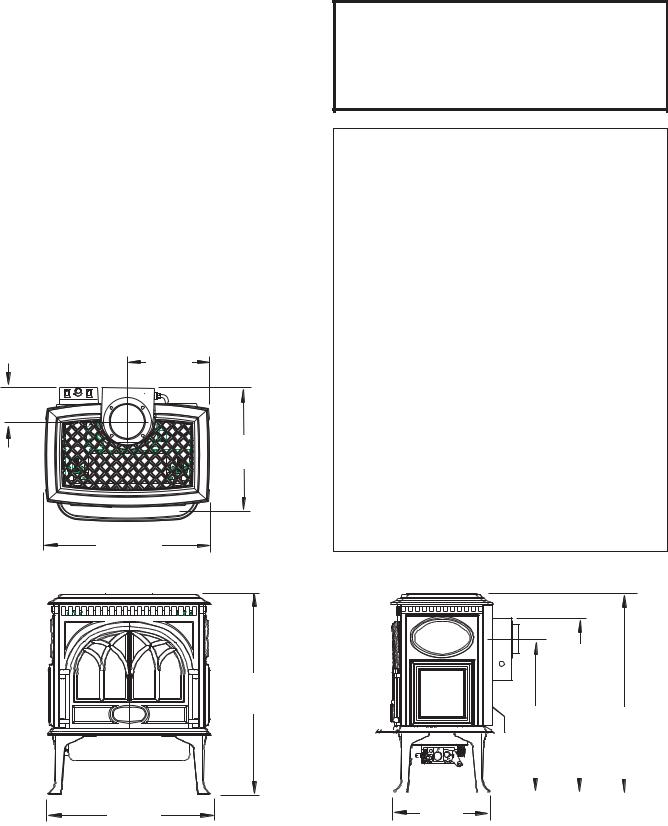
GF 300 BV Allagash
Specifications
The Jøtul GF300 BV Allagash is a atmosphericallyvented gas fireplace heater designed only for vertical venting directly to the outside of the house, using listed, Type B-vent pipe.
Input Rates
Natural Gas
26,000 BTU/hr. maximum input
15,000 BTU/hr. minimum input
Propane
26,000 BTU/hr. maximum input
13,500 BTU/hr. minimum input
Inlet Pressure: |
MIN |
MAX |
||
Natural Gas: |
5.0 WC (1.24 kPa) |
7.0 WC (1.74 kPa) |
||
Propane: |
12.0 WC (2.99 kPa) |
14.9 WC (3.71 kPa) |
||
Manifold Pressure: MIN |
MAX |
|||
|
|
|
|
|
Natural Gas: |
1.2 WC (.30 kPa) |
3.8 WC (.95 kPa) |
||
Propane: |
2.9 WC (.722 kPa) |
11.0 WC (2.74 kPa) |
||
Piezo Ignitor / Standing Pilot
C
L
11 1/2”
292 mm
4 1/2”
114 mm
C
L
16 1/2”
420 mm
23” 584 mm
27 3/4”
705 mm
22 1/4”
565 mm
THIS FIREPLACE IS SHIPPED FROM THE FACTORY FOR USE WITH NATURAL GAS ONLY. FOR USE WITH PROPANE, THE APPLIANCE MUST FIRST BE CONVERTED USING #155592 FUEL CONVERSION KIT PROVIDED. CONVERSION SHOULD BE MADE BEFORE THE APPLIANCE IS INSTALLED. SEE PG. 11.
Suggested Tools for
Installation and Service
•External regulator (for Propane only)
•Piping which complies with local code
•Manual shutoff valve (T-Handle in Massachusetts)
•Sediment trap - if required by code
•Tee joint
•Pipe wrench
•Pipe sealant
•10 mm open end wrench
•1/2”, 7/16” open end wrench or deep socket
•Phillips head screwdriver
•Flat head screwdriver
•1/4” nut driver
•4 mm allen wrench
•Gloves
•Safety glasses
•Torx T20 screwdriver
•Leak test solution
•Reciprocating Saw
•Power Drill
With Short Legs, reduce height by 2 1/4” ( 51 mm)
C
L
Top
ExitFlue
Collar 25” 635 mm
|
|
|
|
|
|
|
|
|
|
|
|
|
|
|
Rear |
|
Exit |
Top |
Plate |
||
|
|
|
|
|
|
|
|
|
21 |
5/8 ” |
27 |
3/4” |
|||||||||
|
|
|
|
|
|
|
|
|
|||||||||||||
|
|
|
|
|
|
|
|
|
|
550 |
mm |
705 |
mm |
||||||||
|
|
|
|
|
|
|
|
|
|
|
|
|
|
|
|
|
|
|
|
|
|
|
|
|
|
|
|
|
|
|
|
|
|
|
|
|
|
|
|
|
|
|
|
|
|
|
|
|
|
|
|
|
|
|
|
|
|
|
|
|
|
|
|
|
|
|
|
|
|
|
|
|
|
|
|
|
|
|
|
|
|
|
|
|
|
|
|
|
|
|
|
|
|
|
|
|
|
|
|
|
|
|
|
|
|
|
|
|
|
|
|
|
|
|
|
|
|
|
|
|
|
|
|
|
|
|
|
|
|
|
|
13” 330 mm
4
General Information
THIS HEATER MUST BE INSTALLED AND MAINTAINED
BY A QUALIFIED SERVICE AGENCY.
The installation and repair of this appliance must be done by a qualified service person. Failure to properly install and maintain this heater could result in an unsafe or hazardous installation, which may result in a fire, explosion, property damage, personal injury or loss of life.
This appliance may be installed in an aftermarket permanently located, manufactured (mobile) home, where not prohibited by local codes.
This appliance is only for use with the type(s) of gas indicated on the rating plate. This appliance is not convertible for use with other gases, unless a certified kit is used.
Cet appareil peut être installé dans un maison préfabriquée (mobile) déjà installée à demeure si les règlements locaux le permettent.
Cet appareil doit être utilisé uniquement avec les types de gas indiqués sur la plaque signalétique. Ne pas l’utiliser ave d’autres gas sauf si un kitde conversion certifié est installé.
This appliance should be inspected before use and at least annually. More frequent cleaning may be required due to excessive lint from carpeting, bedding material, etc. It is imperative that control compartments, burners, and circulating air passageways of the appliance be kept clean.
THIS APPLIANCE MUST NOT BE CONNECTED TO A CHIMNEY OR FLUE SERVING ANY OTHER APPLIANCE.
The installation must conform to local codes. Your local Jøtul dealer can assist you in determining what is required in your area for a safe and legal installation. Some areas require a permit to install a gas burning appliance. Always consult your local building inspector, or authority having jurisdiction, to determine what regulations apply in your area.
CODE COMPLIANCE: Your local officials have final authority in determining if a proposed installation is acceptable. Any requirement that is requested by the local authority having jurisdiction, that is not specifically addressed in this manual, defaults to local code. In the absence of local codes, the installation requirements must comply with the current edition of National codes. In the U.S., these requirements are established in the National Fuel Code, ANSI Z223.1.(NFPA 54) current edition. In Canada, the codes have been established in CAN/CGA B149 Fuel Installation Code, current edition.
Consult the local or national installation code(s) to assure that adequate combustion and ventilation air is available.
Installer l’appareil selon les codes ou reglements locaux, ou, en l’absence de tels reglements, selon les Codes d’installation CAN/CGA-B149.
DO NOT OPERATE THIS STOVE IF ANY PART HAS BEEN
UNDER WATER. Call a qualified service technician to inspect the heater and to replace any part of the control system and any gas control which may have been under water.
Ne pas se servir de cet appareil s’il a ete’ plonge dans l’eau, completement ou en partie. Appeler un technicien qualifie pour inspecter l’appareil et remplacer toute partie du syste’me de controle et toute commande qui ont ete plonges dans l’eau.
Glass Panel
Do not operate this appliance with the glass front removed, cracked, or broken. Replacement of the glass should be done by a licensed or qualified service person. Only remove glass for routine service. Always handle glass carefully.
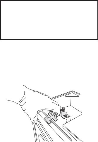
Unpacking your stove
1.Remove the Top Plate of the stove by simply lifting it straight off of the stove body.
2.To open the firebox, disengage the two Glass Frame Latches located on top of the firebox. Pull each handle forward to clear the latch from the notch in the frame.
Glass Frame
 Latch
Latch
3.Familiarize yourself with the installation requirements specified in this manual, before beginning the installation.
Hardware Bag Contents |
|
|
• |
Fuel Conversion Kit - LP................................ |
155592 |
* |
Decorative Pipe Brackets ............................. |
129469 |
5
Safety Information
During normal operation, the GF 300 BV gas stove will reach high surface temperatures. Therefore:
Due to the high operating temperatures, this appliance should be located out of traffic areas and away from furniture and draperies.
Children and adults should be alerted to the hazards of high surface temperatures and should stay away to avoid burns and/or clothing ignition.
Young children should be supervised while they are in the same room as the GF 300 BV gas stove.
Clothing or other flammable materials should not be placed ON or NEAR the GF 300 BV gas stove. Surveiller les enfants. Garder les vetements, les meubles, l’essence ou autres liquides a vapeur inflammables loin de l’appareil.
NEVER store or use gasoline or any other flammable vapors or liquids in the vicinity of the GF 300 BV gas stove.
Never burn any other materials in your GF 300 BV Allagash gas stove, it is strictly designed for use with natural gas or propane fuel ONLY.
· Any safety screen, glass or guard removed for servicing the appliance must be replaced prior to operating the appliance.
Location
In selecting a location for the stove, consider the following points:
1)Heat distribution
2)Vent termination requirements
3)Gas supply line routing
4)Traffic areas, furniture, draperies, etc.
The GF 300 BV may be located on or near conventional construction materials, however, proper clearance to combustibles must be maintained in order to provide adequate air circulation around the appliance. Also, it is important to provide adequate access around the stove for servicing and proper operation.
The clearance and hearth specifications listed in this manual are the minimum requirements for combustible material. A combustible material is anything that can burn (i.e. sheet rock, wall paper, wood, fabrics etc.). These surfaces are not limited to those that are visible and also include materials that may be located behind noncombustibles.
If you are not sure of the combustible nature of a material, consult your local fire officials. “Fire Resistant” materials are considered combustible: they are difficult to ignite, but will burn. Also, “fire-rated” sheet rock is considered combustible.
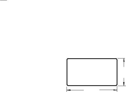
Hearth Requirements
The GF 300 BV gas stove CANNOT be installed directly on carpeting, vinyl, linoleum or Pergo®.
If this appliance will be installed on any combustible material OTHER THAN WOOD, a floor pad must be installed that is either metal or wood, or a listed hearth pad. This floor protection must extend the full width and depth of the appliance. It is not necessary to remove carpeting, vinyl or linoleum from underneath the floor protection. See fig. 1.
Figure 1. Minimum Hearth Protection.
14” (356 mm)
24” (686 mm)
6

Stove and Vent Clearance
Requirements
Minimum Clearances from the Stove to Combustibles
Rear: |
2” (51 mm) - measured from Draft Hood |
|
Ceiling: |
32 1/4” (819 mm) - measured from stove top |
|
Corner: |
3” |
(76 mm) - measured from stove top |
Sides: |
3” |
(76 mm - measured from stove top) |
|
2” |
|
(51 mm) |
|
To Rear Wall |
3” |
3” |
(76 mm) |
(76 mm) |
Minimum Clearances from the Vent Pipe to Combustibles
Horizontal Run: |
|
Top: Off the top of the pipe |
2” (50 mm) |
Sides: Off the sides and bottom |
2” (50mm) |
Vertical Run:
All sides: 1” (25 mm)
All vent components must be installed in accordance with the manufacturer’s instructions and within the terms of their listing. Refer to the manufacturer’s instructions for approved clearances from the vent pipe to combustible materials.
Minimum Alcove Dimensions
Maintain clearances to combustibles as noted above.
Width: |
36” (914 mm) |
|
Depth: |
24” |
(610 mm) |
Height: |
61” |
(1550 mm) |
Figure 2. Parallel Installation Clearances.
|
11 3/4” |
|
|
(298 mm) |
|
3” |
34” |
11 3/4” |
(76 mm) |
||
|
(864 mm) |
(298 mm) |
|
HEARTH |
|
|
3” |
|
|
(76 mm) |
|
Figure 3. Vent adaptor centerline at minimum clearance to corner walls.
Mantel Clearances - Stove shown with standard legs. With Short Legs, subtract 2 1/4” (51 mm) from the clearances indicated below.
Max. Mantel Depth
56 3/4” |
|
|
|
|
|
|
|
|
|
|
|
|
|
|
|
|
|
|
|
|
|
|
|
|
|
|
|
|
53 3/4” |
50 3/4” |
||||
1441 mm |
|
1365 mm |
1289 mm |
|||
55 |
|
1/4” |
|
|
27 3/4” |
|
|
|
|
|
|||
|
52 1/4” |
|
||||
1403 mm |
1327 mm |
705 mm |
||||
|
|
|
|
|
|
|
|
|
|
|
|
|
|
11.5” |
|
|
|
|
|
|
|
9.5” |
|
|
|
|
|
|
|
7.5” |
|
|
|
|
|
|
|
5.5” |
|
|
|
|
|
Mantel Depths |
Mantel Sheild: |
3.5” |
Min. Mantel Depth |
|
|
|
|
||
|
|
|
|
as in Fig.4. |
Min. 24 ga. steel |
||
|
|
|
|
|
|
|
26” wide on 1” |
|
Max. Top Trim |
|
|
|
|
|
spacers |
|
|
|
|
|
|
|
|
|
Depth = 1” |
|
|
|
|
|
|
1” |
|
|
|
|
|
No Top Trim |
|
11” (266 mm) |
|
|
|
|
|
|
|
|
44 |
1/4” |
41 |
1/4” |
38 |
1/4” |
|
|
1124 mm |
1047 mm |
972 mm |
|
|||
|
|
42 3/4” |
39 3/4” |
27 3/4” |
|
||
|
|
1086 mm |
1010 mm |
705 mm |
|
||
|
|
|
|
|
|
|
|
|
|
|
|
|
|
|
|
|
|
|
|
|
|
|
|
|
|
|
|
|
|
|
|
|
|
|
|
|
|
|
|
|
|
|
|
|
|
|
|
|
|
|
|
|
|
|
|
|
|
|
|
|
|
|
|
|
|
|
|
|
|
|
|
|
|
|
|
|
|
|
|
|
|
|
|
|
|
|
|
|
|
|
|
|
|
|
|
|
|
|
|
|
|
|
|
|
|
|
|
|
|
|
|
|
|
|
|
|
|
|
|
|
|
|
|
|
|
|
|
|
|
|
|
|
|
|
|
|
|
|
|
|
|
|
|
|
|
|
|
|
|
|
|
|
|
Max. |
|
||||
|
|
|
|
|
|
|
|
|
|
|
|
|
|
|
|||||
|
|
|
|
|
|
|
|
|
|
|
|
|
6 |
1/2” |
|
||||
|
|
|
|
|
|||||||||||||||
|
|
||||||||||||||||||
|
|
|
|
|
|
|
|
|
|
|
|
|
|
||||||
|
|
|
|
|
|
|
|
|
|
|
|
|
165 mm |
||||||
|
|
|
|
|
|
|
|
|
|
|
|
|
|||||||
|
|
|
|
|
|
|
|
|
|
|
|
|
|||||||
Figure 4. Mantel and Trim specifications - |
Figure 4a. Mantel specifications - |
Stove installed flush with fireplace face. |
Stove recessed into fireplace no more than 6 1/2”. |
7
Vent Requirements
The GF 300 BV Allagash is specifically designed to operate using 4” Type B vent pipe components or a Listed Flexible gas liner.
•All venting components must be installed in accordance with the terms of their listing and manufacturer’s instructions.
•The minimum height of a vertically terminated system shall be no less than 7', and the maximum height shall be no more than 35'. See diagrams page 9.
•With steep roofs, nearby trees, and in predominant windy conditions, poor draft or down draft conditions can occur. In these cases, increasing the height of the vent or high wind termination caps may improve the situation.
•ELBOWS: If an offset or elbow is necessary in the vertical rise, it is important to support the vent pipe every three feet, to avoid excessive stress on the offsets.
•Whenever possible use 45° elbows opposed to 90° elbows. This offers less restrictions for the flow of flue gases.
Maximum number of 90° elbows: three Maximum number of 45° elbows: four
•TOTAL MAXIMUM HORIZONTAL RUN ANYWHERE IN THE VENTING CONFIGURATION IS 4 FEET. The distance between any 45° elbows is considered a horizontal run. See diagrams, page 10.
•Any Type B vent passing through a roof must have a flashing, storm collar, thimble and a Type B cap is required. See diagrams, page 10.
•Venting on the Allagash CANNOT be less than 4” in diameter or greater than 4” in diameter.
•Any unused flue or masonry enclosure can be used as a passage way for venting, but the flue must be relined using Type B 4” vent or Listed Flexible Gas Liner.
•The remaining space around the liner in a masonry or zero-clearance flue CANNOT be used to vent any other appliance.
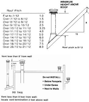
Figure 5. Termination Height Requirements.
•When terminating through the roof refer to the Gas Vent Rule for proper vent termination height.
See fig. 5.
•NO venting may terminate horizontally or below roof eaves.
•Passage through combustibles (walls, ceilings) must be with Type B venting and must maintain listed clearances.
•Any horizontal run should have an upward slope of 1/4” per foot toward the termination cap.
•When venting through a thimble into a masonry flue, any venting exposed in the room must be Type B venting, or a flexible liner sleeve within 24 ga. 6” stove pipe.
•Listed Flexible Gas Liners may not be exposed in any living space.
8
•When 6” diameter decorative pipe is installed to cover the venting any Listed Flexible Gas liner must be connected directly to the stove’s draft hood.
•Use of single wall connector pipe as a vent is prohibited for use with the GF300 Allagash B-Vent stove.
•A firestop is required at every floor.
•Any venting that is exposed above the first floor, regardless of attic space or living space, must be enclosed. Always maintain the required clearance from all sides of the vertical vent system according to manufacture.
•Installation of any components not manufactured or approved by Jøtul or failure to meet all clearance requirements will void all warranties and could result in property damage, bodily injury, or serious fire.
•Never modify any venting component, or use any damaged venting product.
•THE GAS APPLIANCE AND VENT SYSTEM MUST BE VENTED DIRECTLY TO THE OUTSIDE OF THE BUILDING, AND NEVER ATTACHED TO A CHIMNEY SERVING A SOLID FUEL OR GAS BURNING APPLIANCES.
•BE SURE TO MAINTAIN THE PROPER CLEARANCES TO COMBUSTIBLES AS DEFINED IN THIS MANUAL AND IN THE INSTRUCTIONS PROVIDED WITH EACH VENTING COMPONENT.
•When installing at an altitude above 2000’ the minimum vertical rise becomes 12’ from the draft hood.
NOTE:
A chimney system located outside the building envelope may be subject to downdrafting and/or flow reversal. Atmospherically-vented appliances, such as B-Vents, may not be compatible with these chimney systems.
All atmospherically-vented appliances (B-Vents) are affected by atmospheric conditions and house pressurization. For example, a B-Vent appliance vented to an outside chimney system in a basement will likely be subject to negative pressure. This type of installation is not recommended.
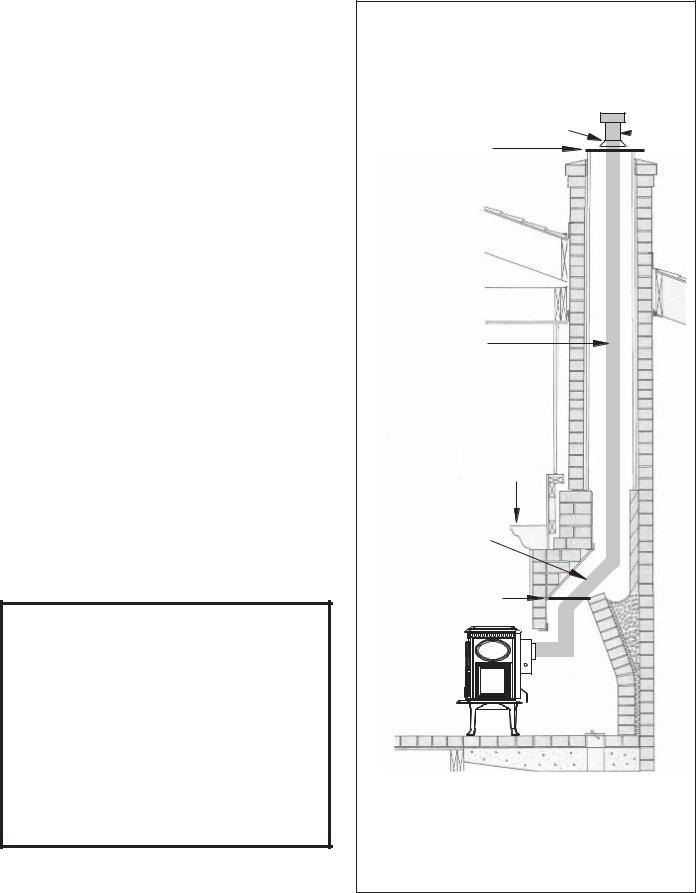
Venting through a Masonry or Prefabricated Manufactured Chimney
Storm collar required
Top sealing
achor plate
Type B vent or Listed Flexible Gas
Liner.
Use of Type B vent liner within outside chimneys is recommended to help keep the gases warm and stabilize draft.
Max. Height 35 ft. Min. Height 7 ft.
Always maintain the proper clearance to mantel and trim
Maximum offset is 4 ft.
Recommended damper sealing plate to seal flue chamber to prevent heat loss
Listed termination cap required
WARNING: FAILURE TO POSITION THE PARTS IN ACCORDANCE WITH THIS DIAGRAM OR FAILURE TO USE ONLY PARTS SPECIFICALLY APPROVED WITH THIS APPLIANCE MAY RESULT IN PROPERTY DAMAGE OR PERSONAL INJURY.
Figure 6. GF 300 BV venting through a masonry chimney.
9
 Loading...