


Jøtul GF3 DVII
Allagash
Direct Vent
Gas Heater
Installation and Operation Instructions
Warnock Hersey
C 

 US
US
WARNING:
IF THE INFORMATION IN THESE INSTRUCTIONS ARE NOT FOLLOWED EXACTLY, A FIRE OR EXPLOSION MAY RESULT CAUSING PROPERTY DAMAGE, PERSONAL INJURY OR LOSS OF LIFE.
FOR YOUR SAFETY:
DO NOT STORE OR USE GASOLINE OR OTHER FLAMMABLE VAPORS AND LIQUIDS IN THE VICINITY OF THIS OR ANY OTHER APPLIANCE.
INSTALLATION:
INSTALLATION AND SERVICE MUST BE PERFORMED BY A QUALIFIED INSTALLER, SERVICE AGENCY OR LICENSED GAS SUPPLIER.
WHAT TO DO IF YOU SMELL GAS:
•DO NOT TRY TO LIGHT ANY APPLIANCE.
•DO NOT TOUCH ANY ELECTRICAL SWITCHES.
•DO NOT USE THE PHONE IN YOUR BUILDING. IMMEDIATELY CALL YOUR GAS SUPPLIER FROM A NEIGHBOR’S PHONE.
•FOLLOW YOUR GAS SUPPLIER’S INSTRUCTIONS.
•IF YOU CANNOT REACH YOUR GAS SUPPLIER, CALL THE FIRE DEPARTMENT.
AVERTISSEMENT:
ASSUREZ-VOUS DE BIEN SUIVRE LES INSTRUCTIONS DANS CETTE NOTICE POUR REDUIRE AU MINIMUM LE RISQUE D’INCENDIE OU POUR EVITER TOUT DOMMAGE MATERIEL, TOUTE BLESSURE OU MORTALIT’E.
NE PAS ENTREPOSER NI UTILISER D’ESSENCE NI OU LIQUIDES INFLAMMABLES DANS LE VOISINAGE DE CET APPAREIL OU DE TOUT AUTRE APPAREIL.
L’INSTALLATION LE SERVICE DOIVENT ETRE EXECUTES PAR UN INSTALLATEUR QUALIFIE, AGENCE DE SERVICE OU LE FOURNISSEUR DE GAZ.
QUE FAIRE SI VOUS SENTEZ UNE ODEUR DE GAZ.
•NE PAS TENTER D’ALLUMER L’APPAREIL
•NE TOUCHEZ A AUCUM NTERRUPTEUR.
•NE PAS VOUS SERVIR DES TELEPHONES SE
TROUVANT DANS LE BATIMENT OU VOUS VOUS TROUVEZ.
•APPELEZIMMEDIATEMENTVOTRE FOURNISSEUR DE GAZ CHEZ UN VOISIN. SUIVEZ LES INSTRUCTIONS DU FOURNISSEUR.
•SI VOUS NE POUVEZ REJOINDRE LE FOURNISSEUR DE GAZ, APPELEZ LE SERVICE DES INCENDIES.

Welcome to Jøtul...
Congratulations on the purchase of your new Jøtul GF3 DVII Allagash gas stove.
We at Jøtul are happy you’ve made the decision to warm your hearth with a Jøtul product. Your new Allagash benefits from our experience as the world’s largest manufacturer of solid fuel burning appliances for over 140 years. We’ve been making fine quality cast iron wood and coal stoves and fireplaces continuously since 1853.
In the Allagash, we’ve combined advanced gas technology with the warm, traditional elements of cast iron. With proper care and use, your Jøtul heater will provide you with many years of safe, dependable, and satisfying service.
The Jøtul Allagash is a direct vented gas heater designed and approved for installation into a variety of installation configurations. Please take a few minutes to familiarize yourself with this manual and the features of your new stove.
Jøtul GF3 DVII Allagash
Direct Vent Gas Heater
Manufactured and Distributed by:
Jøtul A.S.A.
Fredrikstad, Norway
Jøtul North America
Portland, Maine
Test Standards
This appliance complies with |
Warnock Hersey |
|
National Safety standards and is |
C |
US |
tested and listed by Intertek Testing Services of Middleton,
Wisconsin to ANSI Z21.88-1998
(NFPA 54) and CSA 2.33-M98 for Canada.
THIS STOVE IS CONFIGURED TO BURN NATURAL GAS ONLY. IF USE WITH PROPANE GAS IS DESIRED, THE BURNER MUST FIRST BE CONVERTED. FOR YOUR CONVENIENCE, A PROPANECONVERSIONKIT IS INCLUDED WITH THE STOVE.
THIS PRODUCT MUST BE INSTALLED BY A LICENSED MASTER OR JOURNEYMAN PLUMBER OR GAS-FITTER WHEN INSTALLED IN THE COMMONWEALTH OF MASSACHUSETTS.
SUGGESTED TOOL LIST FOR INSTALLATION AND SERVICE:
•External regulator (for LPG only)
•Piping which complies with local code
•Manual shutoff valve
•Sediment trap
•Tee Handle Gas Cock - required for Massachusetts
•Pipe wrench
•Pipe sealant
•10 mm open end wrench
•1/2”, 7/16” open end wrench
•Phillips head screwdriver
•Flat head screwdriver
•1/4” nut driver
•Gloves
•Safety glasses
•Torx T20 screwdriver
•Leak test solution
Table of Contents |
|
Standards ............................................ |
3 |
General Information ........................ |
3 |
Safety Information .......................... |
4 |
Location ............................................... |
4 |
Hearth Requirements ...................... |
4 |
Stove Clearances............................... |
5 |
Mantel and Trim ................................ |
5 |
Venting Requirements .................... |
6 |
Vertical Venting................................. |
6 |
Horizontal Venting ........................... |
7 |
Co-linear Hearthmount .................. |
8 |
Mobile Home Installation .............. |
9 |
Vent Window .................................. |
10 |
Vent Terminal Clearances ............ |
11 |
Fuel Conversion ............................. |
12 |
Gas Connection .............................. |
14 |
Gas Pressures ................................. |
14 |
High Altitude Adjustment .......... |
15 |
Air Shutter Settings ...................... |
16 |
Log Set Installation ....................... |
16 |
Blower Installation ........................ |
17 |
Remote Control / Thermostat ... 18 |
|
System Check ................................. |
19 |
Operation Instructions................. |
20 |
Maintenance ................................... |
20 |
Illustrated Parts List ............... |
22, 23 |
PLEASE READ THESE INSTRUCTIONS IN THEIR ENTIRETY AND MAKE THEM AVAILABLE TO ANYONE USING OR SERVICING THE APPLIANCE.
KEEP THESE INSTRUCTIONS FOR FUTURE USE.
1
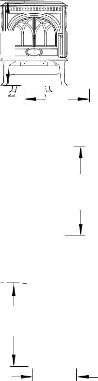
28” 711 mm
22 3/4”
578 mm
Top Exit
27 3/4”
705 mm
Rear Exit
Centerline
24 3/4”
629 mm
13 1/4”
337 mm
Specifications
The Jøtul GF3 DVII Allagash is a Direct Vent wall furnace and is designed as a sealed combustion, air circulating gas appliance for residential applications. The following vent components are approved for use with the Jøtul GF3 DVII, vented directly to the outside of the house:
•Simpson Dura-Vent 6 5/8" X 4" GS pipe
•Security Direct Vent 6/4 vent pipe
•Amerivent 6/4 vent pipe.
The Jøtul GF3 DVII Allagash gas stove is designed to operate on NATURAL GAS or PROPANE only. It manufactured and shipped prepared to burn Natural Gas. For safe and efficient operation the stove is equipped with a millivolt gas control valve with a piezo ignitor. Electrical power is only required when operating the OPTIONAL forced air blower.
Input Rates
Natural Gas
26,000 BTU/hr. maximum input
20,000 BTU/hr. minimum input
Propane
26,000 BTU/hr. maximum input
20,000 BTU/hr. minimum input
Minimum Inlet Pressure:
Natural Gas: |
5.0 WC |
(1.25 kPa) |
Propane: |
11.0 WC |
(2.75 kPa) |
Manifold Pressure: MIN |
MAX |
|
Natural Gas: |
2.0 WC (.85 kPa) |
3.5 WC (.85 kPa) |
Propane: |
6.4 WC (1.60 kPa) |
10.0 WC (2.50 kPa) |
Steady State Efficiency: 82%
A.F.U.E.: 73%
Piezo Ignitor / Standing Pilot
2
Standards
This appliance complies with National Safety standards and is tested and listed by Intertek Testing Services of Middleton,WI
In addition, the Jøtul GF3 DVII Allagash gas stove complies with and has been tested and listed as a direct vent heater and listed to ANSI Z21.88-1998 (NFPA 54), and CSA 2.33-M98 for Canada.
DO NOT ATTEMPT TO ALTER OR MODIFY THE CONSTRUCTION OF THE APPLIANCE OR ITS COMPONENTS. ANY MODIFICATION OR ALTERATION WILL VOID THE WARRANTY, CERTIFICATION AND LISTING OF THIS APPLIANCE.
•Installer l’appareil selon les codes ou reglements locaux, ou, en l’absence de tels reglements, selon les Codes d’installation CAN/CGA-B149.
•DO NOT OPERATE THIS STOVE IF ANY PART HAS BEEN UNDER WATER. Immediately call a qualified service technician to inspect the heater and to replace any part of the control system and any gas control which has been under water.
•Ne pas se servir de cet appareil s’il a ete’ plonge dans l’eau, completement ou en partie. Appeler un technicien qualifie pour inspecter l’appareil et remplacer toute partie du syste’me de controle et toute commande qui ont ete plonges dans l’eau.
General Information
•THIS HEATER MUST BE INSTALLED AND MAINTAINED BY A QUALIFIED SERVICE AGENCY.
•The installation and repair of this appliance must be done by a qualified service person. Failure to properly install and maintain this heater could result in an unsafe or hazardous installation, which may result in a fire, explosion, property damage, personal injury or loss of life.
•This appliance should be inspected before use and at least annually. More frequent cleaning may be required due to excessive lint from carpeting, bedding material, etc. It is imperative that control compartments, burners and circulating air passageways of the appliance be kept clean.
•NOTE: THIS APPLIANCE MUST NOT BE CONNECTED TO A CHIMNEY OR FLUE SERVING ANY OTHER APPLIANCE.
•The installation must conform to local codes. Your local Jøtul dealer can assist you in determining what is required in your area for a safe and legal installation. Some areas require a permit to install a gas burning appliance. Always consult your local building inspector or authority having jurisdiction to determine what regulations apply in your area.
•Your local officials have final authority in determining if a proposed installation is acceptable. Any requirement that is requested by the local authority having jurisdiction, that is not specifically addressed in THIS manual, defaults to local code. In the absence of local codes, the installation requirements must comply with the current National codes. In the U.S. these requirements are established in the National Fuel Code,ANSI Z223.1.(NFPA 54). In Canada, the codes have been established in CAN/CGA B149 Fuel Installation Code.
Glass Front
Do not operate this appliance with the glass front removed, cracked or broken. Replacement of the glass should be done by a licensed or qualified service person. Only remove glass for routine service. Always handle glass carefully.
3

Safety Information
This appliance will reach high surface temperatures during normal operation. Please read the following notes to help ensure safe operation.
•Due to the high operating temperatures this appliance should be located out of traffic and away from furniture and draperies.
•Children and adults should be alerted to the hazards of high surface temperatures and should stay away to avoid burns or clothing ignition.
•Young children should be supervised while they are in the same room as the Allagash gas stove.
•Clothing or other flammable materials should not be placed ON or NEAR the Allagash gas stove. Surveiller les enfants. Garder les vetements, les meubles, l’essence ou autres liquides a vapeur inflammables loin de l’appareil.
•NEVER store or use gasoline or any other flammable vapors or liquids in the vicinity of the Allagash gas stove.
•Never burn any other materials in your Allagash gas stove, it is strictly designed for use with natural gas or propane fuel ONLY.
•Any safety screen, glass or guard removed for servicing the appliance must be replaced prior to operating the appliance.
Location
In selecting a location for the stove, consider the following points:
1)Heat distribution
2)Vent termination requirements
3)Gas supply line routing
4)Traffic areas, furniture, draperies, etc.
The GF100 Nordic QT may be located on or near conventional construction materials, however, proper clearance to combustibles must be maintained in order to provide adequate air circulation around the appliance. Also, it is important to provide adequate access around the stove for servicing and proper operation.
The clearance and hearth specifications listed in this manual are the minimum requirements for combustible material. A combustible material is anything that can burn (i.e. sheet rock, wall paper, wood, fabrics etc.). These surfaces are not limited to those that are visible and also include materials that may be located behind non-combustibles.
If you are not sure of the combustible nature of a material, consult your local fire officials. Remember, “Fire Resistant” materials are considered combustible: they are difficult to ignite, but will burn. Also,“firerated” sheet rock is considered combustible.
Electrical Hazard
When the Allagash gas stove is installed with the optional forced air Blower Kit, the stove must be electrically grounded in accordance with local codes or, in the absence of local codes, with the current NFPA 70National Electrical Code or CSA C22.1-Canadian Code.
The Allagash Blower Kit is supplied with a threeprong (grounding) plug for protection against shock hazard and should be plugged directly into a properly grounded three-prong receptacle.
DO NOT CUT OR REMOVE THE GROUNDING PRONG FROM THE PLUG.
Always unplug the Blower Kit when performing routine service to the Allagash gas stove.
Hearth Requirements
The Allagash gas stove CAN NOT be installed directly on carpeting, vinyl flooring, linoleum or Pergo®. If you wish to install this appliance on any combustible material OTHER THAN WOOD, a floor pad must be installed that is either metal, wood or a listed hearth pad. This floor protection must extend the full width and depth of the appliance. It is not necessary to remove the carpeting, vinyl or linoleum from underneath the floor protection.
Note: the hearth requirements are the same when using the optional short leg package.
4

Clearance Requirements
Minimum clearances for the GF3 DVII Allagash
Rear: 4” / 102 mm Ceiling: 12” / 305 mm Corner: 4” / 102 mm Right Side: 4” / 102 mm
Left Side: 10” / 254 mm (required for complete access of the lighting instructions)
Minimum Clearance for Vent Pipe
Horizontal Runs: |
|
|
Off the top of the pipe: |
|
2" (50mm) |
Off the sides and bottom: |
1" (25 mm) |
|
Vertical Runs, all sides: 1" (25 mm) |
|
|
Alcove Installation |
|
|
Minimum Height off stove top: |
40” / 1006 mm |
|
MinimumWidth of alcove: |
38” / 965 mm |
|
(Assumes 10” off the left side and 4” off the right |
||
side) |
|
|
Maximum Alcove Depth: |
24” / 607 mm |
|
Pipe Clearances:
1” on vertical runs
2” off top of horizontal runs, 1” on other sides.
Mantel and Trim Clearances
Mantel or Trim Depth
|
24” / 607 mm |
|
18” / 457 mm |
A |
5” / 127 mm |
|
B |
|
C |
|
Minimum |
|
Clearance from |
|
the Top Plate |
|
A = 12” |
|
B = 9” |
|
C = 4” |
Figure 1.
Parallel Installation
|
4” |
|
|
102 mm |
|
Left Side |
Right |
|
Side |
||
10” |
4” |
|
254 mm |
||
102 mm |
||
|
Figure 2. Allow 10” on left side of the appliance for complete access to the lighting instructions and control valve.
Corner Installation |
13 1/2” |
|
|
|
337 mm |
4”
102 mm
13 1/2” 16” 
 337 mm 406
mm
36” 910 mm
27” |
|
|
|
|
|
|
|
|
|
|
|
|
|
|
|
|
|
|
|
|
|
|
|
|
|
|
|
686 mm |
|
|
|
|
|
|
|
|
4” |
||||
|
|
|
|
|
|
102 mm |
|||||||
This is not a required |
|
|
|
|
|
|
|
|
|
|
|
|
|
hearth size, although it |
|
|
|
|
|
|
|
|
|
|
|
|
|
|
|
|
|
16” |
|||||||||
is aesthetically |
|
|
|
|
|||||||||
proportional. Assumes |
|
|
406 mm |
||||||||||
|
|
||||||||||||
the stove is 4” off the |
|
|
|
|
|
|
|
|
|
|
|
|
|
corners. |
|
|
|
|
|
|
|
|
|
|
|
|
|
Figure 3. Top Exit Centerlines and possible hearth configuration.
5
Venting Requirements
There are two types of venting configurations approved for use with the Allagash gas stove - Horizontal Termination and Vertical Termination.
The GF3 DVII Allagash is approved for use with the following vent components:
Simpson Dura-Vent GS
Secure Vent - Security Chimneys Intl. Ltd. Amerivent Direct
Installation of any components not manufactured or approved by Jøtul or failure to meet all clearance requirements will void all warranties and could result in property damage, bodily injury, or serious fire. Use parts from one manufacturer only - DO NOT MIX VENT COMPONENTS FROM DIFFERENT MANUFACTURERS IN THE SAME SYSTEM.
The approved vent configurations described herein are derived from extensive testing under controlled laboratory conditions. Gas appliance performance can be negatively affected by variables present in the installation environment, i.e: strong prevailing winds, snow accumulation, etc. These conditions should be taken into consideration by the installer and stove owner.
IMPORTANT
•JOINT SEALING REQUIREMENT: APPLY A 1/8” BEAD OF HIGH-TEMPERATURE (750°F) SEALANT TO THE MALE SECTION OF THE INNER VENT PIPE.
THE CEMENT SHOULD FORM A SEAL BETWEEN THE INNER AND OUTER PIPES.
•NEVER MODIFY ANY VENTING COMPONENT, OR USE ANY DAMAGED VENTING
•FOLLO THE INSTALLATION SEALANT INSTRUCTIONS PRO-
VIDED BY THE VENT MANUFACTURER FOR EACH VENT PART.
•THE GAS APPLIANCE AND VENT SYSTEM MUST BE VENTED DIRECTLY TO THE OUTSIDE OF THE BUILDING AND NEVER ATTACHED TO A CHIMNEY SERVING A SOLID FUEL OR GAS BURNING APPLIANCE. EACH DIRECT VENT GAS APPLIANCE MUST HAVE ITS OWN SEPARATE VENT SYSTEM. COMMON VENT SYSTEMS ARE PROHIBITED.
•IF VENTING SYSTEM IS DISASSEMBLED FOR ANY
REASON, REINSTALL PER THE INSTRUCTIONS PROVIDED FOR THE INITIAL INSTALLATION.PRODUCT.
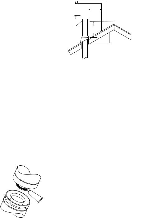
Horizontal Overhang
2 ft. min.
Termination
Cap
|
|
|
2 ft. |
|
Wall |
|
||
|
|
|
|
|
||||
|
|
|
min. |
|
|
|
Vertical |
Lowest |
|
|
|
|
|
|
|
||
|
|
|
|
|
|
|
||
|
|
|
|
|
|
|
||
|
|
|
|
|
|
|
|
Discharge |
|
|
|
|
|
|
|
|
|
2 ft. min.
12 is
2 ft. = minimum height from roof to lowest discharge opening
Figure 4. Vertical Vent Roof Penetration Height.
Vertical Venting Requirements
(Vertical Termination)
·The minimum height of a vertically terminated system shall be no less than 7'. The maximum height shall be no more than 35'.
·With steep roofs, nearby trees, and predominant windy conditions, poor draft or down draft conditions can occur. In these cases, increasing the height of the vent may improve the situation.
·If an offset or elbow is necessary in the vertical rise, it is important to support the vent pipe every three feet, to avoid excessive stress on the offsets. Jøtul recommends the use of Simpson Dura-Vent’s Wall Straps. (#988).
·Whenever possible use 45° elbows opposed to 90° elbows. This offers less restrictions for the flow of flue gases and intake air.
NOTE: Vertical termination may result in reduced flame height and heat output due to the“suction” of natural draft.
·Vertical Termination Height: In no case shall any discharge opening on the cap be less than 2' (610 mm) horizontally from the roof surface. See Figure 4.
·A firestop is required at every floor. The opening should be framed to 10" X 10" inside dimension. Jøtul recommends the use of Simpson Dura-Vent Firestop (#963).
·Any venting that is exposed above the first floor, regardless of attic space or living space, must be enclosed. Always maintain the required 1" clearance from all sides of the vertical vent system.
·It may be necessary to add restriction to a vertical venting installation, so that the draft is not too strong and creates incomplete combustion.
The Allagash is equipped with sliding restriction plates that can be adjusted to compensate for excessive draft. See Figure 5.
6
Restrictor Sliders
|
|
First Restriction |
|
|
Setting - install |
|
|
|
2 |
|
screw into the |
2 |
|
|
12 |
OUTER hole of |
|
12 |
sliders. |
|
|
|
|
Second Restriction Setting - screw installed into
MIDDLE hole of slider.
Figure 5. Vent restrictor settings.
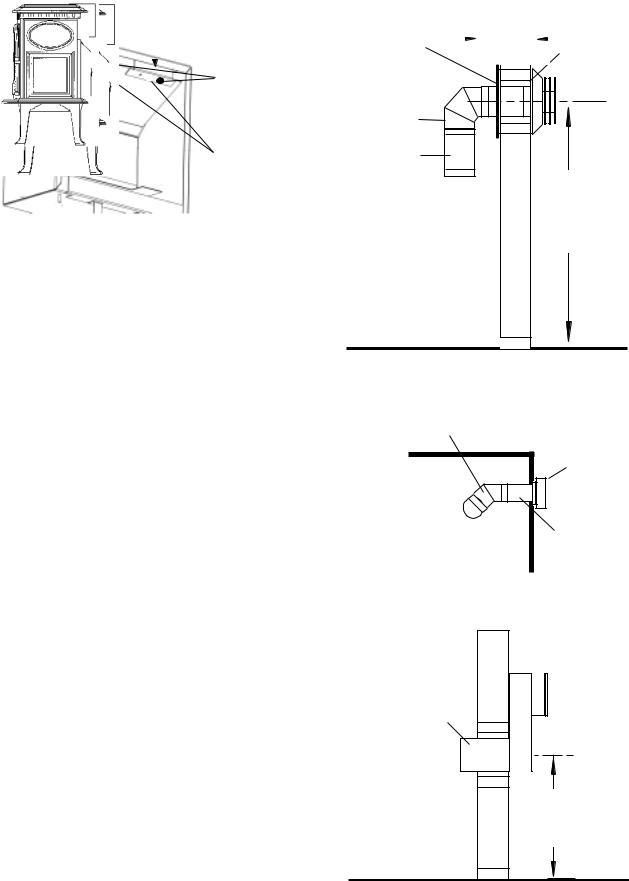
Horizontal Venting Requirements
Follow these guidelines if any part of the installation incorporates a horizontal run or terminates horizontally.
•The maximum horizontal run made directly off the rear of the stove shall be no more than 12" and must then be connected to a 14" snorkel cap (Simpson Dura-vent #982).
•The horizontal termination cap must maintain a 3" clearance to any overhead combustible projections exceeding 2 1/2" or less. Maintain 12" clearance from projections exceeding 2 1/2". See Figure 8, page for complete termination clearance information.
•Any horizontal run of vent must be level or have a 1/4" rise for every foot of run toward the termination cap.
NEVER ALLOW THE VENTING TO SLOPE DOWNWARD, AS HIGH TEMPERATURES MAY RESULT AND CREATE A HAZARDOUS CONDITION.
•Vent Pipe Clearance to Combustible Materials: For all horizontal runs, a 2" top clearance and a 1" side and bottom clearance must be maintained.
•Wall Pass-through: A minimum 10" X 10" square cutout is required to maintain proper clearances through combustible wall construction. The opening must be framed in. Simpson Dura-Vent Wall Thimble #942 or Secure Vent Wall Radiation Shield SV4RSM must be used for the wall pass-through. Optional decorative plates are available to finish the interior side of the wall pass-through.
•IMPORTANT: Follow the vent manufacturer’s installation instructions provided with each vent component.
•DONOTFILLAIRSPACEWITHANYTYPEOFINSULATION.
•MAINTAIN THE PROPER CLEARANCES TO THE TERMINATION CAP. SEE FIG. 10.
•Do not recess the termination cap into a wall or siding.
•Install a Vinyl Siding Standoff between the vent cap and the exterior wall (Simpson Dura-Vent #950). to protect vinyl siding from overheating.
|
|
|
|
|
|
|
|
|
|
|
|
WallThimble |
HorizontalLength |
|
|||
|
12”Max. |
|
Wall Plate |
||
|
|
||||
#942B |
|
|
|||
|
|
|
|
||
|
|
|
|
|
#940B |
|
|
|
|
|
|
|
|
|
|
|
|
|
|
|
|
|
|
|
|
|
|
|
|
90° Elbow
#990B
24” length #904B
55 3/4”
Floor to centerline of minimum vertical rise
NOTE: SHORT LEGS REDUCE THE HEIGHT BY 2 1/4”.
Figure 6. Minimum Vertical Vent - Simpson DuraVent part numbers shown.
Simpson Dura-Vent 45°
Elbow #945B
123
12
12
12
12 12” Max.
12
Horizontal run into a 14” Snorkel Simpson DuraVent (#906B)
Figure 7. Horizontal terminal to corner.
12” Max. Horizontal run into a 14” Snorkel Simpson Dura-Vent (#906B)
14” Snorkel
Simpson
Dura-Vent
(#982)
Rear Exit
Centerline
24 3/4”
628 mm
Figure 7a. Horizontal terminal directly off stove must use a 14” Snorkel termination.
7
 Loading...