


400 F Jøtul
|
Jøtul F 400 |
Installation and Operating Instructions for USA/Canada |
2 |
Monteringog bruksanvisning - Norsk |
21 |
Monteringoch bruksanvisning - Svenska |
27 |
Installation and Operating Instructions - English |
32 |
Manuel d'installation et d'utilisation - Francais |
37 |
Instrucciones para instalación - Español |
42 |
Manuale di installazione ed uso - Italiano |
48 |
Montageund Bedienungsanleitung - Deutsch |
53 |
Installatieen montagehandleiding - Nederlands |
59 |
Monterings-. og bruksanvisningen må oppbevares under hele produktets levetid. These instructions must be kept for future references. Wir empfehlen Ihnen, die Montageund Bedienungsanleitung für spätere Zwecke sorgfältig aufzubewahren. Ce document doit être conservé pendant toute la vie de l'appareil.

USA/Canada
Installation and Operation Instructions for USA/Canada Installation et fonctionnement pour Canada
Safety Notice: If this solid fuel room heater is not properly installed, a house fire may result. For your safety, follow the installation directions. Contact local building or fire officials about restrictions and installation inspection requirements in your area. Kindly save these instructions for future reference.
Avis de sécurité: Une installation non appropriée de ce poêle de chauffage risque de provoquer un incendie. Assurez votre sécurité en respectant les directives d’installation suivantes. Consultez les autorités locales du bâtiment ou de la prévention des incendies au sujet des restrictions et exigences relatives aux inspections d’installations dans votre région.
Tested and listed by ITS, Intertek Testing Services, Middleton,Wisconsin.
Tested to U.S. Standards: ANSI/UL 737 and ANSI/UL 1482, Canadian Standards: CAN/ULC-S627-M93
Standards
The Jøtul F 400 woodstove has been tested and listed to; U.S. Standards: ANSI/UL 737 and ANSI/UL 1482. Canadian Standards: CAN/ULC-S627-M93
Tests performed by:
ITS, Intertek Testing Services, Middleton,WI
Manufactured by:
Jøtul AS, P.O. Box 1411, Fredrikstad, Norway
Distributed by:
Jøtul North America, P.O. Box 1157
400 Riverside Street, Portland, ME 04104
This heater meets the U.S. Environment Protection Agency’s Emissions limits for wood heaters manufactured and sold after July 1, 1990.
Under specific test conditions, this heater has shown heat output at rates ranging from 11,300 to 27,800 BTU’s per hour.
The Jøtul F 400 woodstove is only listed to burn wood. Do not burn any other fuels.
Read this entire manual before you install and use your new room heater.
Save these instructions and make them available to anyone using or servicing the stove.
Check Building Codes
When installing, operating and maintaining your Jøtul F 400 woodstove, follow the guidelines presented in these instructions, and make them available to anyone using or servicing the stove.
Your city, town, county or province may require a building permit to install a solid fuel burning appliance.
In the U.S., the National Fire Protection Association’s Code, NFPA 211, Standards for Chimneys, Fireplaces, Vents and Solid Fuel Burning Appliances, or similar regulations, may apply to the installation of a solid fuel burning appliance in your area.
In Canada, the guideline is established by the CSA Standard, CAN/CSA-B365-M93, Installation Code for Solid-Fuel- Burning Appliances and Equipment.
Always consult your local building inspector or authority having jurisdiction to determine what regulations apply in your area.
Jøtul North America
400 Riverside Street
Portland, Maine 04104
Jøtul pursues a policy of continual product development. Products as supplied may therefore differ in specification, colour, or type of accessories, from those illustrated or otherwise described in publications and brochures.
2
Table of Contents |
|
Standards and Safety Notices |
|
Standards / Codes ..................................................................... |
2 |
Safety Notices ............................................................................. |
3 |
Installation .................................................................................. |
3 |
Assembly Before Installation |
|
Unpack the Stove ..................................................................... |
4 |
Flue Collar Reversal ................................................................. |
4 |
Chimney Connector ................................................................ |
4 |
Chimney Requirements ......................................................... |
4 |
Masonry Chimneys .................................................................. |
4 |
Prefabricated Chimneys .......................................................... |
5 |
Chimney Height ......................................................................... |
5 |
Wall Pass-Throughs ................................................................... |
5 |
Connecting to the Chimney |
|
Masonry Chimney .................................................................... |
6 |
Hearthmount / Fireplaces ...................................................... |
6 |
Prefabricated Chimneys ......................................................... |
6 |
Clearances to Combustibles |
|
Floor Protection ........................................................................ |
6 |
Clearances to Walls and Ceilings .......................................... |
6 |
Using Shields to Reduce Clearances .................................... |
7 |
Alcove Installation ..................................................................... |
7 |
Mobile Home Installation ....................................................... |
7 |
Clearance Diagrams ................................................................. |
8 |
Clearance Chart ......................................................................... |
9 |
Operation |
|
Wood Fuel ................................................................................. |
10 |
Controls ...................................................................................... |
10 |
Break-in Procedure .................................................................. |
10 |
Starting / Maintaining the Fire ........................................... |
10 |
Adding Fuel ................................................................................ |
11 |
Formation of Creosote ........................................................... |
11 |
Maintenance |
|
Ash Removal .............................................................................. |
11 |
Glass Care ................................................................................... |
11 |
Cleaning ...................................................................................... |
11 |
Glass Removal .......................................................................... |
12 |
General Maintenance |
|
Gaskets ....................................................................................... |
12 |
Gasket replacement ................................................................ |
12 |
Gasket List .................................................................................. |
12 |
Chimney System ..................................................................... |
12 |
Accessories |
|
Firescreen ................................................................................... |
12 |
Stove-top Thermometer ....................................................... |
13 |
Outside Air Kit ........................................................................... |
13 |
Floor Bracket Kit ...................................................................... |
13 |
Rear Heat Shield ....................................................................... |
13 |
Bottom Heat Shield ................................................................. |
13 |
Illustrations |
|
Figures ................................................................................ |
14 - 17 |
Parts Diagram and List ........................................................... |
18 |
Appendix A |
|
Alternate Floor Protection ..................................................... |
18 |
USA/Canada
Safety Notices
•Burn solid wood fuel only.
•Do not use chemicals or fluids to start the fire. Do not burn garbage or flammable fluids.
•If this room heater is not properly installed, a house fire may result. To reduce the risk of fire, follow the installation instructions. Failure to follow these instructions may result in property damage, bodily injury, or loss of life.
•Contact the local building or fire officials about restrictions and installation inspection requirements in your area.
•Do not connect this stove to any air distribution duct or system.
•Extremely hot while in operation! Keep children, clothing and furniture away. Contact will cause skin burns.
•Avoid creating a low pressure condition in the room where the stove is operating. Be aware that operation of an exhaust fan or clothes dryer can create a low pressure area and consequently promote flow reversal through the stove and chimney system. In some cases, the optional Outside Air Kit #154335 can be used to alleviate this condition. The chimney and building, however, always work together as a system - provision ofoutside air, directly or indirectly to an atmospherically vented appliance will not guarantee proper chimney performance. Consult your local Jøtul authorized dealer regarding specific installation/performance issues.
•Jøtul recommends that this stove be installed by a professional solid fuel technician or that you consult one if you do the work yourself. Also, consult your insurance company regarding any other specific requirements.
Installation
If this solid fuel room heater is not properly installed, a house fire may result. For your safety,follow the installation directions. Contact the local building or fire officials about restrictions and installation inspection requirements in your area.
Your local officials have final authority in determining if a proposed installation is acceptable. Any requirement by the local authority having jurisdiction that is not specifically addressed in this manual, defaults to NFPA 211, and local codes in the U.S. or in Canada, CAN/CSA-B365-M and local codes.
3
USA/Canada
Assembly Before Installation
Unpack the Stove
Inspect the stove for damage. Contact your dealer immediately if any damage is found. Do not install the stove if any damage is evident.
Contents:
•Inspection Cover (Not for use in US/Canada)
•Door Handle
•Hardware Bag
Flue Collar Reversal
The Flue Collar is oriented in the Top Exit position. If a Rear Exit position is required, remove the two mounting bolts, and turn the collar 180 degrees. Secure the collar using the same bolts, nuts and washers.
Chimney Connector
Use 6” single wall or listed 6” double-wall stovepipe to connect the stove to the chimney. Single wall stovepipe must be black iron or stainless steel and have a minimum thickness of 24 gauge. Do not use aluminum or galvanized steel pipe for chimney connection - these materials are not suitable for use with solid fuel.
Follow these guidelines regarding chimney connector construction:
•Do not use chimney connector as a chimney.It is intended only for use as a connection device.
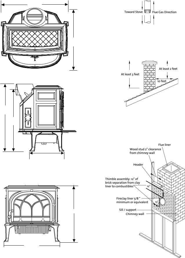
•Each connector section must be oriented with the male (crimped) end pointing toward the stove. See fig. 2.
•Secure all connector joints with three sheet metal screws.
•For the best performance, the chimney connector should be as short and direct as possible, including no more than two 90° elbows.
•The maximum vertical run of single wall stovepipe should not exceed 10 ft. (305 cm). The maximum horizontal run should not exceed 3 ft. (92 cm) with a 1/4” rise per foot.
•No part of the chimney connector may pass through an attic or roof space, closet or other concealed space, or through a floor or ceiling. All sections of the chimney connectors must be accessible for cleaning. Where passage through a wall or partition of combustible construction is desired, the installation must conform with NFPA 211 or CAN/CSA-B365, and is also addressed in this manual.
•Do not connect this stove to a chimney flue servicing another appliance.
Chimney Requirements
There are two types of chimneys suitable for the Jøtul F
400 :
1.A code-approved masonry chimney with a ceramic tile or listed steel flue liner.
2.A prefabricated chimney complying with the requirements for Type HT (2100°F) chimneys per UL 103 or ULC S629.
The chimney size should not be less than the cross-sectional area of the flue collar, and not more than three times greater than the cross-sectional area of the flue collar.
When selecting a chimney type and the location for the chimney in the house, keep this in mind: It is the chimney that makes the stove work, not the stove that makes the chimney work. This is because a chimney actually creates a suction, called “draft” which pulls air through the stove. Several factors affect draft: chimney height, cross-sectional area (size), and temperature of the chimney, as well as the proximity of surrounding trees or buildings.
A short masonry chimney on the exterior of a house will give the poorest performance. This is because it can be very difficult to warm the chimney thereby creating inadequate draft. In extremely cold climates, it may be necessary to reline the chimney or extend its height to help establish draft.
A tall, interior masonry chimney is easier to keep warm and will perform the best under a variety of weather and environmental conditions.
The following guidelines give the necessary chimney requirements based on the national code (ANSI-NFPA 211 for the US. And CSA CAN-B365 for Canada). However, many local codes differ from the national code to take into account climate, altitude, or other factors. Your local building inspector is the final approving authority. Consult them prior to installation.
Do not connect the stove to any air distribution duct or system.
Masonry Chimneys
When installing the Jøtul F 400 into a masonry chimney you must conform to all of the following guidelines:
•The masonry chimney must have a fireclay liner or equivalent, with a minimum thickness of 5/8” (14 mm) and must be installed with refractory mortar. There must be at least ½” (12.7 mm) air space between the flue liner and chimney wall.
•The fireclay flue liner must have a nominal size of 8” X 8” (20 cm x 20 cm), and should not be larger than 8”X 12” (20 cm x 30 cm). A round fireclay liner must have a minimum inside diameter of 6” (15 cm) and maximum inside diameter of 8” (20 cm). A larger chimney should be relined with an appropriate code approved liner.
4
•Brick or modular block must be a minimum of 4” (10 cm) nominal thickness. Stone construction must be at least 12” (30 cm) thick.
•A newly-built chimney must conform to local codes, or, in their absence, must comply with national regulations.
•An existing chimney must be inspected by a professional licensed chimney sweep, fire official, or code officer to ensure that the chimney is in proper working order.
•No other appliance may be vented into the same flue.
•An airtight clean-out door should be located at the base of the chimney.
Prefabricated Chimneys
A prefabricated metal chimney must be tested and listed for use with solid fuel burning appliances. HighTemperature (HT) Chimney Standard UL 103 for the U.S. and High Temperature Standard ULC S-629 for Canada.
The manufacturer’s installation instructions must be followed precisely. Always maintain the proper clearance to combustibles as established by the pipe manufacturer. This clearance is usually a minimum of 2”, although it may vary by manufacturer or for certain chimney components.
Chimney Height
The chimney must be at least 3 feet (92 cm) higher than the highest point where it passes through the roof and at least 2 feet (61 cm) higher than the highest part of the roof or structure that is within 10 feet (3.05 m) of the chimney, measured horizontally. See figure 3.
Chimneys shorter than 14 feet (4.27 m) may not provide adequate draft. Inadequate draft can result in smoke spillage when loading the stove, or when the door is open. Poor draft can also cause back puffing (ignition of gas buildup inside the firebox) and sluggish performance. The minimum height does not, in itself, guarantee proper chimney performance.
Excessive chimney height can promote over-strong draft resulting in high stove temperatures and short burn times. Excessive draft can be corrected by installing a butterfly damper. Your Jøtul dealer is an expert resource to consult regarding draft issues or other performance-related questions.
Wall Pass-Throughs
In the U.S.
The National Fire Protection Association’s publication, NFPA 211, Standard for Chimneys, Fireplaces,Vents and Solid Fuel Burning Appliances permits four methods for passing through a combustible wall. Before proceeding with any method be sure to consult with your local building officials to discuss any local code requirements.
USA/Canada
Common Method:
•See figures 4 and 5. Remove all combustible materials from the pass-through area ( around the chimney connector), a minimum 12” (30.5 cm). A 6” (15.2 cm) diameter connector will require a 31” x 31” (78.7 x 78.7 cm) square opening.
•The opening must be filled with at least 12” (30.5 cm) of brick around a fireclay liner.The liner must be ASTM C35 or equivalent, having a minimum wall thickness of 5/8” (16 mm).
•The Pass-through must be at least 18” (45.7 cm) from combustible ceiling materials.
•It will be necessary to cut wall studs, install headers, and construct a sill frame to maintain the proper dimensions and to support the weight of the brick.
•The bricks must be solid brick with a minimum of 3 ½ inches thick (nominal 4” / 102 mm).
•Refractory mortar must be used at the junction of the chimney and the pass-through liner. The pass-through liner must not penetrate the chimney liner beyond the inner surface of the chimney liner. Use extreme care when constructing the hole in the chimney liner as the tiles can shatter easily.
In Canada
The installation must conform to CAN/CSA-B365,
Installation Code for Solid Fuel Burning Appliances and Equipment. Before proceeding be sure to consult your local building inspector.
Common Method:
•This method requires the removal of all combustible materials from at least 18” (45.7 cm) around the chimney connector’s proposed location. A 6”round liner requires a minimum opening 43” x 43” (109.2 x 109.2) square.
•Locate the pass-through at least 18” from combustible ceiling materials.
•The space that is cleared of combustible materials must remain empty. Sheet metal panels can be used to cover the area. However, when using a panel on both sides of the wall, each cover must be installed on noncombustible spacers at least 1” from the wall. If one panel of sheet metal is to be used it may be installed flush to the wall.
See section 5.3.1 and 5.3.2 of CAN/CSA - B365-M91. Consult your local building inspector, authorized Jøtul Dealer, NFPA 211 in the U.S. or CAN/CSA-B635 in Canada for other approved wall pass-through methods.
5

USA/Canada
Connecting to the Chimney
Masonry Chimney
When installing a Jøtul F 400 into a masonry chimney through a“thimble”(the opening through the chimney wall to the flue), the thimble must consist of ceramic tile or steel and be securely cemented in place.
The chimney connector/stove pipe must slide completely inside the thimble to the inner surface or the flue liner. It may be necessary to make use of a thimble sleeve (a pipe with a slightly smaller diameter than standard stove pipe). See figure 5.
The connector pipe or thimble sleeve must not protrude into the flue liner or otherwise restrict draft.
Use refractory cement to seal the seam between the chimney connector, sleeve, and thimble.
Do not connect this stove to a chimney flue servicing another appliance of any kind.
Hearthmount into a Masonry Fireplace
The Jøtul F 400 may be installed into a masonry fireplace provided the height of the opening is a minimum of 29 1/2”. Use of the Short Leg Package will reduce the stove height by 2 1/4” (57 mm).
Building code requires that the fireplace damper plate be removed or securely fixed in the open position. A connector pipe must then extend from the stove’s flue exit through the damper area of the fireplace and into the chimney tile liner. See figure 6.
The inside area of the flue liner must not be less than the area of the stove flue collar and cannot be more than three times greater than the cross sectional area of the stove flue collar.
If the chimney liner is too large to accommodate the stove, an approved relining system must be installed to resize the flue.
A new sheet metal damper block-off plate must be installed around the connector pipe at the damper frame and sealed with the proper sealant (usually High-Temp Silicone).
Prefabricated Chimneys
When connecting the Jøtul F 400 to a prefabricated metal chimney always follow the pipe manufacture’s instructions and be sure to use the components that are required. This usually includes some type of“smoke pipe adapter” that is secured to the bottom section of the metal chimney and allows the chimney pipe to be secured to it with three sheet metal screws. See figure 7.
Clearance to Combustibles
Floor Protection (For both U.S. and Canada)
The Jøtul F 400 requires one of the following three forms of hearth protection:
1.Any UL,ULC or WH listed hearth board. (No bottom heat shield required).
2.Any noncombustible material that has a minimum R- value of 2.0. (No bottom heat shield required.)
3.Any noncombustible material with the use of the stove’s bottom heat shield.
All forms of protection must include a noncombustible surface extending a minimum of 18” (460 mm) in front of the stove, and 8” (200 mm) from the sides and back of the stove (measured from side and back panels).
This will result in a minimum floor protection of 42”W X 44”D. See figure 8.
In a rear vent installation, the floor protection must also extend under the stove pipe a minimum of 2” (50 mm) beyond either side of the pipe. See figure 8.
Consult appendix A at the back of this section for alternate floor protection methods and materials.
Clearances to Walls and Ceilings
The clearances listed and diagramed in this manual have been tested to UL and ULC standards and are the minimum clearances to combustible materials specifically established for the Jøtul F 400 .
A combustible surface is anything that can burn (i.e. sheet rock, wall paper, wood, fabrics etc.). These surfaces are not limited to those that are visible and also include materials that are behind noncombustible materials.
If you are not sure of the combustible nature of a material, consult your local fire officials.
Remember: “Fire Resistant” materials are considered combustible; they are difficult to ignite, but will burn. Also “Fire-rated” sheet rock is also considered combustible.
Contact your local building officials about restrictions and installation requirements in your area.
See pages 8-9 for complete clearance requirements and diagrams.
6
Using Shields to Reduce Clearances
Chimney Connector Heat Shields: Use only connector heat shielding listed for use with solid fuel heaters. The connector heat shield must begin 1” above the lowest exposed point of the connector pipe and extend vertically a minimum of 25” (640 cm) above the top surface of the stove.
Double Wall Connector: Listed double wall pipe is an acceptable alternative to connector pipe heat shields.
Wall-Mounted Protection: When reducing clearances through the use of wall mounted protection:
•In the U.S. refer to NFPA 211, Standard for Chimneys, Fireplaces, Vents and Solid Fuel Burning Appliances, for acceptable materials, proper sizing and construction guidelines.
•In Canada, refer to CAN/CSA-B365, Installation Code for Solid-Fuel Burning Appliances and Equipment, also for acceptable materials, proper sizing and construction guidelines.
Stove Mounted Heat shield: Rear Heat Shield #154385 is approved for use with the Jøtul F 400 in the US. and Canada.
No other heat shield may be used.
Notice: Many manufacturers have developed woodstove accessories that permit clearance reduction. Use only those accessories that have been tested by an independent laboratory and carry the laboratory’s testing mark. Be sure to follow all of the manufacturer’s instructions.
Alcove Installation
The Jøtul F 400 can be installed in an Alcove as diagrammed in figures 9 and 10.
1.The stove must be installed with listed double wall pipe.
2.In a protected alcove installation both side walls and rear wall must be protected per NFPA 211 or CAN/CSAB365. The wall protection must be elevated 1” (25 mm) from the floor and spaced at least 1” (25 mm) off the combustible wall, using noncombustible spacers, to allow for air circulation behind the shield.
3.The height of the wall protection including the bottom air space must be 48” (121 cm).
4.The Bottom Heat Shield is required in all Alcove installations.
5.Alcove floor protection must consist of a UL/ULC or WHI listed hearth pad or a non combustible material with a minimum R value of 2.0.
6.Minimum ceiling height in an unprotected installation, off the top of the stove is 58”(148 cm). The minimum ceiling height off the top of the stove in a protected ceiling installation is 36 (91.5 cm).
USA/Canada
Mobile Home Installation
The Jøtul F 400 has been approved for use in mobile homes in the U.S. and Canada with the following stipulations:
1.The stove must be secured to the floor of the mobile home. Use Floor Bracket Kit #750304.
2.The stove is provided outside air for combustion. Outside Air Kit #154335 (see page 16 for more details).
3.Use only listed double-wall pipe for the chimney connection.
4.The stove must be grounded to the mobile home chassis.
5.The stove must otherwise be installed in accordance to 24CRR, Part 3280 (HUD).
Consult with your local building inspector or fire officials about restrictions and requirements in your area, prior to installing the stove.
Warning!
Do not install this stove in a bedroom/sleeping room. Do not install the stove in any way that might compromise the structural integrity of the mobile home floor, walls, ceiling, or roof.
7
USA/Canada |
|
|
|
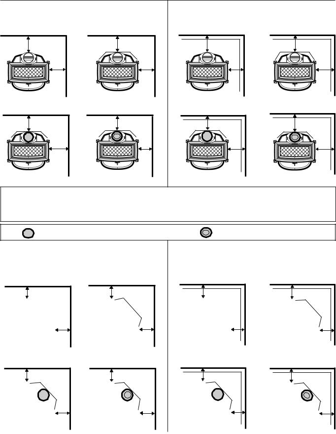
Jøtul F 400 Woodstove Clearances |
|
||
Unprotected Surface |
|
Protected Surface |
PER NFPA 211 or |
Parallel to the Wall |
|
Parallel to the Wall |
CAN/CSA-B365 |
|
|
||
B |
H |
E |
K |
A |
G |
D |
J |
N |
T |
Q |
W |
M |
S |
P |
V |
Important:
Connector heatshields and double wall pipe must be a listed product.
Always follow the manufacturer’s instructions.
= SINGLE WALL PIPE WITH CONNECTOR SHIELDS |
= DOUBLE WALL PIPE |
Unprotected Surface |
|
Protected Surface |
PER NFPA 211 or |
Corner Installation |
|
Corner Installation |
CAN/CSA-B365 |
|
|
||
C |
I |
F |
L |
C |
|
F |
L |
O |
U |
R |
X |
O |
U |
R |
X |
8 |
|
|
|
USA/Canada
Jøtul F 400 Woodstove Clearances
Stove |
Unprotected Surface |
|
Protected Surface Installation |
|||||||||
Clearances |
Installation |
|
PER NFPA211 OR CAN/CSA -B365-M93 |
|||||||||
|
|
|
|
|
|
|
|
|
|
|
|
|
Stove -no heatshield |
Side |
Rear |
|
Corner* |
Side |
|
|
Rear |
|
Corner* |
||
19" A |
25" B |
|
18" C |
11” D |
|
|
7" E |
|
8" F |
|||
single wall pipe |
485mm |
635mm |
|
460mm |
280mm |
|
180mm |
205mm |
||||
|
|
|
|
|
|
|
|
|
|
|
|
|
Stove -with rear heatshield |
18" G |
18" H |
|
13" I |
11” J |
|
|
7” K |
|
8" L |
||
single wall pipe |
460mm |
460mm |
|
330mm |
280mm |
|
180mm |
205mm |
||||
|
|
|
|
|
|
|
|
|
|
|
|
|
Stove -no heatshields |
16” |
|
19” |
|
13” |
8” |
|
|
7” |
|
6” |
|
double wall pipe |
405mm |
485mm |
|
330mm |
205mm |
|
180mm |
150mm |
||||
|
|
|
|
|
|
|
|
|
|
|
|
|
Stove -with rear heatshield |
15" M |
7" N |
|
11" O |
8" P |
|
|
7" Q |
|
6" R |
||
with connector shield |
380mm |
180mm |
|
280mm |
205mm |
|
180mm |
150mm |
||||
|
|
|
|
|
|
|
|
|
|
|
|
|
Stove -rear heatshield |
15" S |
7" T |
|
11" U |
8" V |
|
|
7" W |
|
6" X |
||
with double wall pipe |
380mm |
180mm |
|
280mm |
205mm |
|
180mm |
150mm |
||||
|
|
|
|
|
|
|
|
|
||||
Connector |
Unprotected Surface |
|
Protected Surface |
|
||||||||
Clearances (Pipe) |
Vertical Installation |
per NFPA211 |
Vertical Inatallation |
|
||||||||
|
|
|
|
|
|
OR CAN/CSA-B365-M93 |
|
|||||
Single wall pipe |
25" |
|
|
|
|
12" |
|
|
|
|
|
|
|
|
635mm |
|
|
|
300mm |
|
|
|
|||
Single wall pipe |
18” |
|
|
|
|
7” |
|
|
|
|
|
|
with rear heatshield |
460mm |
|
|
|
180mm |
|
|
|
||||
|
|
|
|
|
|
|
|
|
|
|
|
|
Single wall pipe |
7" |
|
|
|
|
7" |
|
|
|
|
|
|
with connector shields |
180mm |
|
|
|
180mm |
|
|
|
||||
|
|
|
|
|
|
|
|
|
|
|
|
|
Double wall pipe |
7" |
|
|
|
|
7" |
|
|
|
|
|
|
|
|
180mm |
|
|
|
180mm |
|
|
|
|||
Connector |
Unprotected Surface |
|
Protected Surface |
|
||||||||
Clearances (Pipe) |
Horizontal Installation |
Horizontal Installation |
|
|||||||||
|
|
|
|
|
|
|
per NFPA211 OR CAN/CSA-B365-M93 |
|||||
Single wall connector |
18" |
460mm |
|
7" |
180mm |
|
|
|
||||
Double wall Pipe |
6" |
150mm |
|
6" |
150mm |
|
|
|
||||
|
|
|
|
|
|
|
|
|
|
|||
Mantel and Trim |
Stove to 1" thick or less, side trim |
|
|
|
13" |
300mm |
|
|||||
Clearances |
Stove to 1" thick or less, top trim |
|
|
|
23" |
585mm |
|
|||||
|
|
Stove to mantelmaximum mantel depth 12" |
25" |
635mm |
|
|||||||
9
USA/Canada
Operation
Please read the following section completely, before building a fire in your new Jøtul F 400 .
Use Solid Wood Fuel Only
First this stove is designed to burn natural wood only.Wood that has been air-dried for a period of 6 to 14 months will provide the cleanest, most efficient heat.
Do not burn: |
*Treated or painted wood |
*Coal |
|
*Garbage |
*Chemical Chimney cleaners |
*Cardboard |
*Colored paper |
*Solvents |
*Any synthetic fuel or logs |
The burning of any of these materials can result in the release of toxic fumes. Never use gasoline, gasoline-type lantern fuel, kerosene, charcoal lighter fluid, or similar liquids to start or “freshen-up” the fire. Always keep such liquids away from the heater at all times.
Important: Never build or allow the fire to rest directly on the glass panel. The logs should always be spaced at least one inch from the glass to allow for proper air flow within the firebox.
Controls on the Jøtul F 400
Combustion air is controlled by the Primary Air Lever, located above the ashlip on the front of the stove. The lever actuates a shutter over the air inlet which regulates the volume of primary air entering the firebox and affects heat output and burn time.
When first starting or reviving the fire: the primary control lever should be at the far right position, which allows the maximum amount of air into the stove. The greater the amount of air entering the stove, the hotter and faster the fire will burn. Moving the lever to the left reduces the airflow into the stove which prolongs the fire at a lower heat output. See figure 11.
Air Flow / Performance
Primary air enters the firebox directly above the glass panel on the door.The incoming air creates a turbulent barrier or “airwash” between the glass and the fire. Reducing the flow of primary air directly reduces the effectiveness of the airwash. Determining the primary air setting for the best overall performance for your particular needs and installation will only be established over time through trial and error.
Break-In Procedure
The Jøtul F 400 is constructed of cast iron and stove furnace cement. This type of construction requires the stove to be “broken-in” gradually so that heat expansion
does not occur too quickly and cause damage. The following steps describe the proper break-in procedure for the Jøtul F 400 :
1.Light a small fire of newspaper and kindling. Only allow the stove to reach a maximum surface temperature of 200°F (93° C). Burn for approximately 1 hour.
2.Allow the stove to cool to room temperature.
3. Light a second fire, allowing the stove to reach a maximum temperature of 300°F (149°C) for 1 hour.
4.Cool the stove to room temperature.
5.Light a third fire and gradually allow the stove to reach a surface temperature of 400°F (204°C).
6. Cool stove to room temperature. This completes the “break-in” procedure.
To monitor the stove’s temperature, use a magnetic stovetop thermometer, placed directly on the corner of the stove’s top plate.
Note: Keep the stove under 400°F (204°C) surface temperature during any “break-in fire”, with the exception of the last “break-in” fire. If the temperature exceeds 400°F, move the primary air control lever all the way to the left to shut off the air supply completely. It is normal that the stove top temperature will continue to climb until the fuel burns down somewhat. Once the fire is out and the stove has cooled to room temperature, continue the breakin procedure. Never attempt to reduce the temperature by removing burning logs from the fire.
Note: It is normal for a new painted stove to emit an odor and smoke during its first several fires. This is caused by the seasoning of the high temperature paint and will diminish with each fire. Opening a window or door to provide additional ventilation will alleviate this condition.
Starting and Maintaining a Fire
Burn only solid wood directly on the bottom grate of the stove. Do not elevate the fire in any way.
•The ash pan door on the stove must always be securely closed when the stove is in operation.
•Burning the stove with the Ash Door open will over-fire the stove and cause interior damage.
1.With the primary air control lever in the full open position (to the right), start with several sheets of crumbled newspaper placed directly on the grate. On top of the newspaper, place several pieces of small dry kindling (approx. 1” in diameter) with two to three larger logs (approx. 3” to 5” in diameter) on top.
2.Light the fire and close the door, slowly building the fire by adding larger and larger logs. Be sure to follow the break-in procedure before creating a hot fire that might damage the stove.
3.Once the stove has reached a surface temperature range of between 400° and 600°, (204°C -316°C), adjust the primary air control lever as necessary to generate the heat output and burn time desired.
Jøtul recommends use of a magnetic stove top thermometer to monitor the surface temperature of the stove. The optimum surface temperature range for
10
the most efficient burn is between 400° and 600° (204°C -316°C).
See figure 12 for the best locations to place a stove-top thermometer.
Never overfire the stove. If any part of the stove or chimney glows, you are overfiring. A house fire or serious damage to the stove or chimney could result. If this condition occurs, immediately close down the air control.
Adding Fuel
When reloading the stove while it is still hot and a bed of hot embers still exist, follow this reloading procedure:
•Always wear gloves when tending to the stove.
•Push the air control lever to the full open position (far right).
•Wait a few seconds before opening the door.
•Use a stove tool or poker to distribute the hot embers equally around the firebox.
•Load the fuel, usually with smaller logs first.
•Close the door, be sure to latch the door tightly.
•Wait 5 – 10 minutes before adjusting the primary air to the desired heat output setting. (If you have at least a 2” thick ember bed when reloading, it may be possible to close the door and immediately adjust the air control setting).
The Formation of Creosote
When wood is burned slowly and at low temperatures, it produces tar and other organic vapors, which combine with moisture to form creosote. The slow moving smoke carries the creosote vapors, which condense in the cooler chimney flues, and this creosote then sticks to the chimney walls.
The creosote that accumulates in the chimney is highly flammable and is the fuel of chimney fires. To prevent chimney fires it is important to have the chimney and chimney connector pipe inspected and/or cleaned semiannually. A qualified chimney sweep or other authorized service person can provide this service.
It is also important to remember that chimney size, temperature and height all affect draft which in turn affects the formation of creosote. Be sure to follow the installation and operation guidelines established in this manual.
USA/Canada
Maintenance
Ash Removal
For your protection always wear safety gloves when handling the ash pan.
Ash removal will be required periodically depending on how frequently the stove is used. The Jøtul F 400 is equipped with an exterior ash pan assembly that allows easy ash removal without opening the front door.
The ash pan door is located under the front ashlip of the stove. To open the ash door, engage the receptacle end of the door handle with the square fitting on the ash door latch. Rotate the door counterclockwise to unlatch the door and clockwise to latch the door.
With a gloved hand, grasp the ash pan handle and remove the ash pan. Always close the ash pan door before leaving to dispose of the ashes.
The ashes should be placed in a metal container equipped with a tight sealing lid. The container should be placed on a noncombustible floor or on the ground, well away from all combustible materials, pending final disposal. If the ashes are disposed of by burial in soil or otherwise locally dispersed, they should be retained in the closed container until all cinders have thoroughly cooled.
Glass Care
Cleaning
On occasion it will be necessary to clean the carbon deposits and fly ash off of the glass. If the carbon and fly ash are allowed to remain on the glass for an extended period of time it could eventually cause the glass to become etched and cloudy. Any creosote that might develop on the glass will burn off during the next hot fire.
Follow this cleaning procedure:
1. Glass needs to be completely cool.
2. Only use a cleaner that is specifically designed for this purpose. The use of abrasives will damage the glass and ultimately leave the glass frosted.
3. Rinse and dry glass completely before burning the stove.
Caution! Always operate the door slowly and carefully to avoid cracking or breaking the glass. Never use the door to push wood into the firebox. If the glass becomes cracked or broken follow the replacement procedure below. Never operate the stove with a cracked or broken glass panel.
Important: Replace glass only with ceramic glass panel specifically designed for the Jøtul F 400 . Do not use substitutes. Replacement glass is available from your local Jøtul dealer.
11
USA/Canada
Glass Removal
1.Remove the door from the stove and place on a flat surface.
2.Carefully remove all of the glass clips from the inside of the door.
3.Gently remove the glass panel and gasketing.
4.Using a wire brush, remove all remaining debris from the glass area .
5. Apply a small bead of gasket/stove cement and the new gasket. Do not overlap the ends of the gasket rope.
6.Center the new glass panel over the gasket and reinstall the glass clips. See figure 13.
7.It may be necessary to retighten the glass clips after the stove has be burned and the gasketing has been seated.
Important: It is extremely important to tighten the glass clips slowly and in an alternating pattern as you would tighten the lugs on an automobile wheel.
General Maintenance
As with your car, regular maintenance will prolong the life of your stove and ensure satisfactory performance.
At least once per year you should perform the following maintenance procedures:
•Thoroughly clean the stove. Use a soft cloth with soap and water to clean enamel surfaces. Be sure the stove is cold, before cleaning.
•Empty stove of all soot and ashes. Only use a vacuum for this job if the vacuum is specifically designed for ashes.
•Inspect the stove seams. Use a utility light to inspect the stove inside and out for cracks or leaks. Replace all cracked parts and repair any cement leaks with furnace cement.
Gaskets
Check door and glass panel gaskets for tightness. To check the seal of the front door, close and latch the door on a dollar bill and slowly try to pull the dollar bill free. If it can be easily removed, the seal is too loose. Check several spots around the door, and repeat the procedure on the ash pan door as well.
Gasket Replacement
1.Use pliers and a putty knife to remove the old gasket from the door.
2.Thoroughly clean the channel with a wire brush.
3.Apply a small bead of cement to the channel.
4.Gently press the new gasket into the cement to seat it in the channel. Close and latch the door and then reopen. Wipe any excess cement squeezed out from around the gasket.
Gasket List for the Jøtul F 400
Description |
Size |
Length |
Top Plate Gasket |
3/8" LD |
7 |
Smoke Outlet Gasket |
3/16” LD/SA |
3' |
Ash Housing Gasket |
3/16” LD/SA |
4' |
Ash Door Gasket |
5/16” LD |
4' |
Glass Gasket |
3/8" LD |
5' |
Door Gasket |
5/16" LD |
5,8' |
Chimney System
The Jøtul F 400 is designed to burn cleanly and efficiently when used according to the guidelines in this manual. In order to maintain proper performance, you should inspect the chimney and chimney connector at least twice a year and clean when creosote and fly ash deposits exceed 1/4” in any part of the system. Failure to keep the chimney system free of creosote and build up could result in a serious chimney fire.
Accessories
Use only accessories that are specifically designed for use with the Jøtul F 400 .
Firescreen (# 129650)
The Jøtul F 400 has been approved for use as an open fireplace, with front door open. Care should be taken when operating the stove as a fireplace.
•Always have the Firescreen in place, attached to the stove front.
•Never overload the stove. For the best appearance, burn logs in the traditional three log configuration.
•When you operate the stove with the screen in place, efficiency is sacrificed for the sake of aesthetics, much as with a conventional fireplace. Wood will burn at a much faster rate as combustion air is uncontrolled. Most of the heat value of the wood will be lost up the chimney.
Not all installations will support the use of the firescreen. Moderate or low draft conditions may result in smoke spillage from the stove when using the firescreen.
12
Warning: Operate your Jøtul F 400 with the front door fully open and the firescreen in place or fully closed. A partially opened door may result in overfiring. Also, if the door are left partly open, gas and flame may be drawn out of the stove opening, creating risks from both fire and smoke.
Stove-Top Thermometer (# 5002)
Jøtul recommends the use of a magnetic stove-top thermometer to monitor the surface temperature of the stove. The optimum surface temperature range for the most efficient, clean burn is between 400° and 600°.
Outside Air Kit (#154335)
Your local building code may require that an outside air supply be connected to the stove. Jøtul Outside Air Kit 154335 must be used in these installations unless otherwise specified by the local code official.While the use of outside air may be beneficial in some installations, in itself, such a system does not guarantee proper chimney performance. The Outside Air Kit includes an adapter collar to attach the air duct to the stove. Installation will require these additional materials not included in the kit:
1.3” (80 mm) diameter flexible metallic Air Duct - of appropriate length to reach from the stove to the outside of the house.
2.Weatherproof Duct Cap for the duct termination on the outside of the house.
3.Rodent Screen - no larger than 1/4” (5 mm) mesh.
Outside air should be considered if:
1.The stove does not“draw”steadily. Smoke rollout occurs when the door are opened. Fuel burns poorly. Backdrafts occur with or without a fire burning.
2.Other fuel-fired equipment in the house, such as fireplaces or other heating appliances, smell, do not operate properly, suffer smoke roll-out when opened, or back-draft whether or not there is combustion present.
3.Opening a window slightly on a calm (windless) day alleviates any of the above symptoms.
4.The house is equipped with a well-sealed vapor barrier and tight fitting windows and/or has any powered devices that exhaust house air.
5.There is excessive condensation on the windows in the winter.
6.A ventilation system is installed in the house.
If these or other indications suggest that infiltration air is inadequate to supply sufficient air for the stove, additional combustion air should be provided from the outdoor. Outside combustion air can be provided to the appliance by the following means:
1.Direct connection: The Jøtul F 400 has been tested and approved for use with the outside air kit listed above.
2.Indirect method: Outside air is ducted to a point no closer than (12”) 300 mm from the stove, to avoid affecting
USA/Canada
the performance of the appliance.
3.A mechanical ventilation system: If the house has a ventilation system (air change or heat recovery):
a.The ventilation system may be able to provide sufficient combustion makeup air for the solid-fuel appliance.
b.The homeowner should be informed that the ventilation system might need to be rebalanced by a ventilation technician after installation of the appliance.
Note: Provision of outside air to the stove, directly or indireclty, may fail to remedy the problems outlined above. Chimney performance is determined by a variety of interelating factors which may not be affected by the air supply.Your local Jøtul authorized dealer is your best resource for information regarding chimney and stove performance issues.
Floor Bracket Kit (#750304)
Use of the Floor Bracket Kit is required in all mobile home installations to secure the stove to the floor. Complete installation instructions and diagrams are supplied with each Floor Bracket Kit.
Rear Heat Shield (# 154385)
A stove rear heat shield has been specifically designed for the Jøtul F 400 to reduce clearances off the rear of the stove to combustible materials. Use of the heat shield does not affect the clearance off the sides of the appliance. See pages 8-9 for specific clearance requirements. Complete installation instructions are supplied with the heat shield.
No other type of heat shield may be used on the rear of the Jøtul F 400 .
Bottom Heat Shield (# 154384)
The bottom heat shield supplied with your stove has been specifically designed for the Jøtul F 400 . It is required in all alcove installations. Use of the bottom heat shield does not affect the floor protection requirements described on page 6 of this manual.
No other type of heat shield may be used on the bottom of the Jøtul F 400 .
13
USA/Canada
Fig. 1
Fig. 2
25 3/4”
23 1/4”
Fig. 3
29 1/2” top exit
25 1/2” rear exit
Fig. 4
13”
28 1/2”
26 1/2”
14

Fig. 5
Fig. 6
Fig. 7
USA/Canada
Fig. 8
Fig. 9
Fig. 10
Protection and air space must comply with NFPA 211OR CAN/CSA-B365.
15

USA/Canada
Fig. 11
Fig. 12
Fig. 13
Draw. no. 1-1714
16
USA/Canada
17

USA/Canada
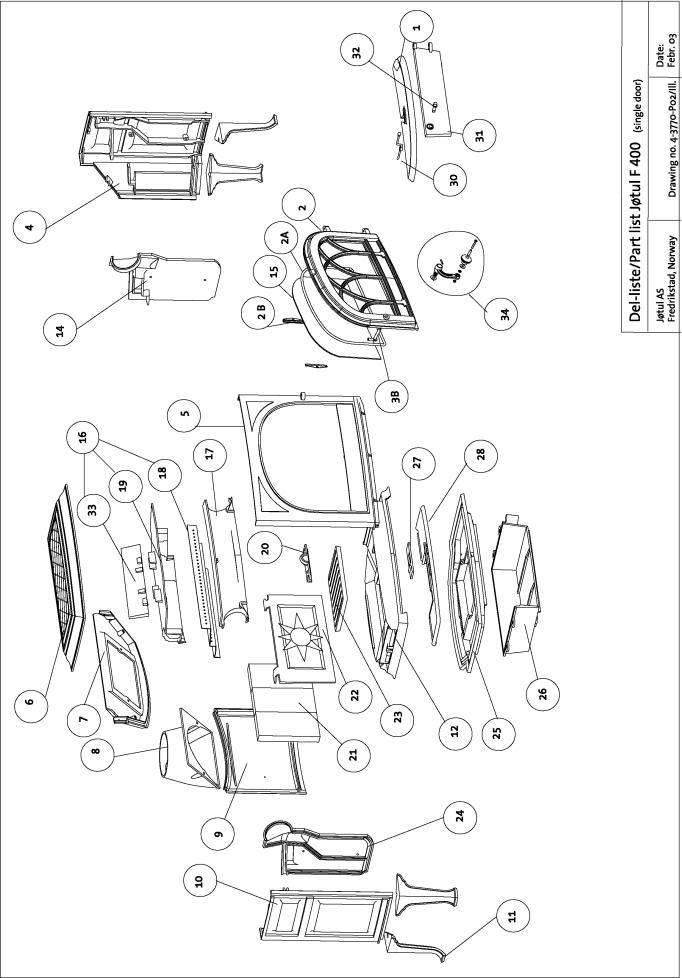
Parts list for the Jøtul F 400 woodstove
Consult your dealer for part numbers and replacement parts.
1Ashlip
2 |
Door |
2A |
Gasket |
2B |
Glass clips |
3B |
Latch |
4 |
Right side panel |
5 |
Front panel |
6Top casting
7 Upper back panel
8 Smoke outlet
9Back panel
10Left side panel
11Leg (long leg)
12Upper bottom panel
13Front door handle
14Right burn plate
15Glass panel
16Airchamber
17Air wash manifold
18Top baffle (stainless steel)
19Baffle cover (cast iron)
20Air inspection cover
21Rear burn plate
22Fire brick (3)
23Bottom grate
24Left burn plate
25Lower bottom panel
26Ashpan housing
*Ashpan
27Air slider/valve
28Air devider
30Air control lever (chrome) Allen head screw
31Ashpan door
*Ashpan door pin 32 Ash door handle 33 Baffle plate II 34 Latch compl.
*Not shown
Appendix A
Alternate floor protection
All floor protection materials must be non-combustible ie. metal, brick, stone, mineral fiber boards). Any combustible material may not be used.
The easiest means of determining if a proposed alternate floor material meets requirements listed in this manual is to follow this procedure.
R-value = thermal resistance k-value = thermal conductivity C-value = thermal conductance
1 . Convert the specification to R-value;
a. If R-value is given, no conversion is needed.
b.If k-value is given with a required thickness (T) in inches:
R=1/k X T.
c. If C-value is given: R=1/C.
2.Determine the R-value of the proposed alternate floor protector. a. Use the formula in Step 1 to convert values not expressed
as “R”.
b.For multiple layers, add R-values of each layer to determine overall R-value.
3. If the overall R-value of the sustem is greater than the R-value of the specified floor protector, the alternate is acceptable.
Example:
The specified floor protector should be 3/4” thick material with a k- factor of 0.84. The proposed alternate is 4” brick with a C-factor of 1.25 over 1/8” mineral board with a k-factor of 0.29.
Step A. Use formula above to convert specifications to R-value. R=1/ k X T= 1/.84 X .75 = .893
Step B. Calculate R of proposed system.
•4” brick of C-1.25, therefore
•R brick = 1/C = 1/1.25 = 0.80.
•1/8” mineral board of k = 0.29 therefore
•R mineral board = 1/.29 X 0.125 = 0.431
Total R = R brick + R mineral board= 0.8 + 0.431=1.231
Step C. Compare proposed system R = 1.231 to specified R of 0.893. Since R is greater than required, the system is acceptable.
Definitions:
Thermal conductance =
C = Btu = W (hr)(ft2)(F) (m2)(K)
Thermal conductivity = |
|
W |
|
= (Btu) |
|||||
k = |
|
Btu |
|
= |
|
||||
(hr)(ft2)(F) |
|
|
(m2)(K) |
(hr)(ft)(F) |
|||||
Thermal resistance= |
= |
|
(m2)(K) |
= (Btu)(inch) |
|||||
R = |
|
Btu |
|
||||||
|
|
|
|
|
W |
(hr)(ft2)(F) |
|||
(hr)(ft2)(F) |
|
|
|
||||||
The Jøtul F 400 Castine woodstove requires floor protection with a minimum insulating r value of 0.5.
Alcove installation require a minimum r value of 1.6. (If a ul/ulc or whi listed hearth pad is not used.)
18
19

NORSK
20
Innhold |
|
Forhold til myndighetene |
|
Tekniske data for Jøtul F 400 ................................................... |
21 |
Sikkerhetsregler ........................................................................... |
22 |
Brannforebyggende tiltak ........................................................ |
22 |
Installasjon av Jøtul F 400 |
|
Fundamentering ......................................................................... |
22 |
Skorstein ........................................................................................ |
22 |
Luftsirkulasjon .............................................................................. |
22 |
Montering før installasjon ........................................................ |
22 |
Kontroll av funksjoner ............................................................... |
23 |
Montering av røykrør ................................................................ |
23 |
Tilslutning til skorstein .............................................................. |
23 |
Bruksanvisning |
|
Første gangs opptenning og daglig bruk ........................... |
24 |
Ved første gangs oppfyring ..................................................... |
24 |
Daglig bruk ................................................................................... |
24 |
Vedlikehold |
|
Rengjøring av glass .................................................................... |
24 |
Fjerning av aske ........................................................................... |
24 |
Rensing og sotfjerning i produktet ....................................... |
24 |
Feiing av røykrør til skorstein .................................................. |
25 |
Kontroll av ildstedet ................................................................... |
25 |
Utvendig vedlikehold ................................................................ |
25 |
Vedlengde-, mengde-, og kvalitet .......................................... |
25 |
Jøtuls definisjon av kvalitetsved ............................................. |
25 |
Servicearbeider |
|
Utskifting av brennplater .......................................................... |
25 |
Utskifting av hvelv ...................................................................... |
25 |
Ekstrautstyr |
|
Korte bein ...................................................................................... |
25 |
Skjermplate - bak ........................................................................ |
25 |
Figurer-tegninger ............................................... |
64-65 |
NORSK
Forhold til myndighetene
Jøtul F 400 er et rentbrennende produkt og har produktdokumentasjon for luftforurensning og brannteknisk sikkerhet utstedt av SINTEF, Norges Branntekniske Laboratorium med registreringsnr. SINTEF 045-089 Dette er påført produktets typeskilt.
Installasjon av et ildsted må være i henhold til det enkelte lands lover og regler og din forhandler kan tilby deg hjelp for å sørge for at installasjonen er sikker og lovlig.
Monterings-, installasjonsog bruksanvisninger er vedlagt produktet. Installasjonen kan først tas i bruk når den er kontrollert av godkjent kontrollør.
Ifølge Forskrift om brannforebyggende tiltak og tilsyn, skal eier melde fra til kommunen når det har vært installert nytt ildsted ellerforetatt andre vesentlige endringer ved fyringsanlegget.
Det er viktig å forsikre seg om at pipen er riktig dimensjonert for ildstedet og at pipetilslutningen er tett og fungerer korrekt. Røykgass som trenger inn i lukkede rom kan representere en alvorlig helsefare.
Et typeskilt av varmebestandig material er plassert på skjermplaten for askehuset. Det inneholder følgende informasjon; produsent, adresse, produktnavn, katalognummer, produksjonsnummer, effekt, godkjenningsnummer.
Tekniske data for Jøtul F 400:
Materiale: |
Støpejern |
|
Overflatebehandling: |
Sort lakk og emalje |
|
Type brensel: |
Ved |
|
Maks. vedlengde: |
50 cm |
|
Trekksystem: |
Luftspyling |
|
Forbrenningssystem: |
Sekundærforbrenning |
|
Røykuttak: |
Topp/bak |
|
Røykrør: |
Ø 150 mm |
|
Mulighet for stålpipe: |
Ja |
|
Vekt ca.: |
158 kg |
|
Tilleggsutstyr: |
Skjermplate-bak, korte ben (155 |
|
Produktmål, |
mm) |
|
Se fig. 1 |
||
brannmurmål |
21
 Loading...