


Jøtul F 3 CB
Woodstove
....................................
InstallationandOperatingInstructionsforUSA
InstallationetfonctionnementpourCanada ....................
Safety notice: If this solid fuel room heater is not properly installed, a house fire may result. For your safety, follow the installation directions. Contact local building or fire officials about restrictions and installation inspection requirements in your area. Kindly save these instructions for future reference.
Avis de sécurité: Une installation non appropriée de ce poêle de chauffage risque de provoquer un incendie. Assurez votre sécurité en respectant les directives d’installation suivantes. Consultez les autorités locales du bâtiment ou de la prévention des incendies au sujet des restrictions et exigences relatives aux inspections d’installations dans votre région.
Tested and listed by ITS Intertek Testing Services, Middleton,Wisconsin. Tested to U.S. Standards: ANSI/UL 1482, Canadian Standards: CAN/ULC-S627-M93

TABLE OF CONTENTS: |
|
|
|
|
|
22 7/8” |
|
|
|
|
|
|
|
|
|
|
|
|
|
|
|
|
|
|
|
|
|
|
|
|
|
|
|
|
|
||
Standards and Safety Notices |
3 |
|
|
|
|
|
|
|
|
|
|
|
|
|
|
|
|
|
|
|
|
|
|
|
|
|
|
|
|
|
|
|
|
|
|
||
|
|
|
|
|
|
|
|
|
|
|
|
|
|
|
|
|
||
|
|
|
|
|
|
|
|
|
|
|
|
|
|
|
|
|
||
|
|
|
|
|
|
|
|
|
|
|
|
|
|
|
|
|
||
Installations.......................................... |
4 |
|
|
|
|
|
|
|
|
|
|
|
|
|
|
|
|
|
Chimney Requirements............................. |
6 |
|
|
|
|
|
|
|
|
|
|
|
|
|
|
|
|
|
Masonry Chimney............. |
6 |
|
|
|
|
|
|
|
|
|
|
|
|
|
|
|
|
|
Prefabricated Chimney............. |
6 |
|
|
|
|
|
|
|
|
|
|
|
|
|
|
|
|
|
Wall pass-throughs............ |
7 |
|
|
|
|
|
|
|
|
|
|
|
|
|
|
|
|
|
.............................Connecting to the Chimney |
8 |
|
|
|
|
|
|
|
|
|
|
|
|
|
|
|
28” |
|
Masonry chimneys |
8 |
|
|
|
|
|
|
|
|
|
|
|
|
|
|
|
||
|
|
|
|
|
|
|
|
|
|
|
|
|
|
|
|
|
||
...............Hearthmount/Fireplaces |
9 |
|
|
|
|
|
|
|
|
|
|
|
|
|
|
|
|
|
Prefabricated Chimney............... |
9 |
|
|
|
|
|
|
|
|
|
|
|
|
|
|
|
|
|
Clearances........................................................ |
10 |
|
|
|
|
|
|
|
|
|
|
|
|
|
|
|
|
|
Floor requirements............. |
10 |
|
|
|
|
|
|
|
|
|
|
|
|
|
|
|
|
|
Stove Clearances............. |
11 |
|
|
|
|
|
|
|
|
|
|
|
|
|
|
|
|
|
Wall shields |
12 |
|
|
|
|
|
|
|
|
|
|
|
|
|
|
|
|
|
|
|
|
|
|
|
|
|
|
|
|
|
|
|
|
|
|
||
|
|
|
|
|
|
|
|
|
|
|
|
|
|
|
|
|
||
Alcove Installations...................................... |
13 |
|
|
|
|
|
|
|
|
|
|
|
|
|
|
|
|
|
Operation ...................................................... |
14 |
|
|
|
|
|
|
|
|
|
|
|
|
|
|
|
|
|
Controls.................... |
14 |
|
|
|
|
|
|
|
|
|
|
|
|
|
|
|
|
|
Breaking in your Stove |
14 |
|
|
|
|
|
|
|
|
|
|
|
|
|
|
|
|
|
|
|
|
|
|
|
|
|
|
|
|
|
|
|
|
|
|||
Starting/Maintaining................... |
15 |
|
|
|
|
|
|
|
|
|
|
|
|
|
|
|
|
|
Formation of Creosote................... |
16 |
|
|
|
|
|
|
|
|
|
|
|
|
|
|
|
|
|
Maintenance.................................................. |
16 |
|
|
|
|
|
|
|
|
|
|
|
|
|
|
|
|
|
...............Ash Removal |
16 |
|
|
|
|
|
|
|
|
|
22 1/2” |
|||||||
Glass Care |
16 |
|
|
|
|
|
|
|
|
|
||||||||
|
|
|
|
|
|
|
|
|
centerline of |
|||||||||
General Maintenance................ |
17 |
|
|
|
|
|
|
|
|
|
rear exit |
|||||||
Gaskets................ |
17 |
|
|
|
|
|
|
|
|
|
|
|
|
|
|
|
|
|
|
|
|
|
|
|
|
|
|
|
|
|
|
|
|
|
|||
Accessories |
18 |
|
|
|
|
|
|
|
|
|
|
|
|
|
|
|
|
|
|
|
|
|
|
|
|
|
|
|
|
|
|
|
|
20 1/4” |
|||
Firescreen |
18 |
|
|
|
|
|
|
|
|
|
|
|
|
|
|
|
||
|
|
|
|
|
|
|
|
|
|
|
|
|
|
|
with short |
|||
Floor Bracket Kit................. |
18 |
|
|
|
|
|
|
|
|
|
|
|
|
|
|
|
|
legs |
Stove -Top Thermometer................. |
18 |
|
|
|
|
|
|
|
|
|
|
|
|
|
|
|
installed |
|
..........................................Parts Diagram |
18-19 |
|
|
|
|
|
|
|
|
|
|
|
|
|
|
|
|
|
Appendix A (alternate floor protection)............ |
20 |
|
|
|
|
13” |
|
|
|
|
|
|
|
|
|
|||
|
|
|
|
|
|
|
|
|
|
|
|
|
|
|||||
7 5/16”
14 9/16”
SAVE THESE INSTRUCTIONS AND MAKE
THEM AVAILABLE TO ANYONE USING
OR SERVICING THE STOVE.
2

STANDARDS
The F 3 CB wood stove has been tested and listed to;
U.S. Standards: ANSI/UL 737 and ANSI/UL 1482.
Canadian Standards: CAN/ULC-S627-M93
Tests performed by ITS, Intertek Testing Services, Middleton, WI
Manufactured by Jøtul A.S.A., P.O. Box 135 Fredrikstad, Norway
Distributed by Jøtul North America, P.O. Box 1157 400 Riverside Street
Portland, ME 04104
This heater meets the U.S. Environment Protection Agency’s Emissions limits for wood heaters manufactured and sold after July 1, 1990.
Under specific test conditions, this heater has shown heat output at rates ranging from 11,500 to 43,500 BTU’s per hour.
The Jøtul F 3 CB wood is ONLY listed to burn wood . Do not burn any other fuels.
JØTUL F 3 CB WOODSTOVE
When installing, operating and maintaining your Jøtul F 3 CB woodstove, follow the guidelines presented in these instructions, and make them available to anyone using or servicing the stove.
A number of areas require a building permit to install a solid fuel burning appliance. In the U.S., the National Fire ProtectionAssociation’s Code, NFPA 211, Standards for Chimneys, Fireplaces, Vents and Solid Fuel Burning Appliances, or similar regulations, may apply to the installation of a solid fuel burning appliance in your area.
In Canada, the guideline is established by the CSA Standard, CAN/CSA-B365-M93, Installation Code for Solid-Fuel-Burning Appliances and Equipment. Always consult your local building inspector or authority having jurisdiction to determine what regulations apply in your area.
NOTICES
·BE SURE TO READ THIS ENTIRE MANUAL BEFORE YOU INSTALL OR USE YOUR NEW JØTUL F 3 CB WOOD STOVE.
·IF THIS ROOM HEATER IS NOT PROPERLY INSTALLED, A HOUSE FIRE MAY RESULT. TO REDUCE THE RISK OF FIRE, FOLLOW THE INSTALLATION INSTRUCTIONS. FAILURE TO FOLLOW THESE INSTRUCTIONS MAY RESULT IN PROPERTY DAMAGE, BODILY INJURY, OR EVEN DEATH.
·Jøtul recommends that you have your new Jøtul F 3 CB installed by a professional installer of solid fuel burning appliances.
·EXTREMELY HOT WHILE IN OPERATION! KEEP CHILDREN, CLOTHING AND FURNITURE AWAY. CONTACT MAY CAUSE SKIN BURNS.
·Avoid creating a low pressure condition in the room where the stove is operating. Operating an exhaust fan or a clothes dryer could create a low pressure area, causing poisonous gases to come out of the stove into the room.
You can prevent low pressure conditions by providing adequate combustion air within 24” but not closer than 12” from the stove. Or, simply install the optional outside air manifold system, which allows the direct connection of air from outside the house to the stove.
·Do not use chemicals or fluids to start the fire. Some fuels will, during combustion, separate carbon monoxide and generate it in the burn chamber. Carbon monoxide is toxic, so please follow the guidelines in this manual for proper operation of your Jøtul F 3 CB.
·If you for some reason experience smoke “rollout” from the stove, it may activate smoke detectors if installed in the house.
DO NOT CONNECT THIS STOVE TO ANY AIR DISTRIBUTION DUCT OR SYSTEM.
3
INSTALLATION
IFTHISSOLIDFUELROOMHEATERISNOTPROPERLY INSTALLEDAHOUSE FIRE MAYRESULT. FORYOUR SAFETY,FOLLOWTHEINSTALLATIONDIRECTIONS. CONTACTTHELOCALBUILDINGORFIREOFFICIALS ABOUT RESTRICTIONS AND INSTALLATION INSPECTIONREQUIREMENTSINYOURAREA.
Reminder:
Your local officials have final authority in determining if a proposed installation is acceptable. Any requirement, that is requested by the local authority having jurisdiction, that is not specifically addressed in THIS manual, defaults to NFPA 211, and local codes in the U.S. or in Canada, CAN/ CSA-B365-M and local codes.
INSTALLING THE VENTING
The F 3 CB can be vented from the top, the rear or from either the right or left side. Follow the instructions below for the desired venting location.
TOP EXIT VENTING
When top exit venting is desired, use a 3mm allen wrench to remove the two set screws that secure the top casting to the sides of the stove and lift off the top casting. Lay the top casting on a flat surface upside down and remove the 10mm bolt from the traverse bar and remove the smoke outlet cover.
Reinstall the top casting, be sure to secure with the two set screws that were removed. See figure 1.
REAR EXIT VENTING
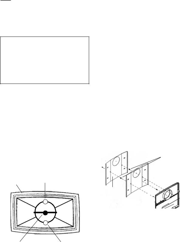
When rear exit venting is desired it will be necessary to “knock-out” the vent hole from the rear casting.
Remove the top casting of the stove by removing the two 3mm set screws that secures the top to the sides. The set screws are located on the outside of the stove on the top of each side panel.
Using a 10mm wrench remove the double rear heatshields from the back of the stove. Remove the front door to avoid damage to the glass. Reminder: loss of the door washer will result in improper door alignment when reinstalling the door.
Using a claw hammer or a small sledge hammer strike the CENTER of the 6” “knock-out” disc from the OUTSIDE of the stove. The “knock-out” disc will break into four wedges and may need to be tapped out. Touch up any remaining sharp edges with a file or hand grinder.
NOTE: The IVORY F 3 CB’s ARE REAR VENTED FROM THE FACTORY. IT IS NOT NECESSARY TO “KNOCK-OUT” THE REAR CASTING OF THE STOVE. HOWEVER, IF TOP EXIT IS DESIRED IT IS NECESSARY TO INSTALL A SMOKE OUTLET COVER ON THE REAR OUTLET OF THE STOVE.
SPACERS
UPSIDE DOWN |
STOVE PIPE STOP |
|
TOP CASTING |
||
|
234
234
234
123
123
123
123
TRAVERSE BAR SECURING |
STOVE PIPE STOP |
|
|
SMOKE OUTLET COVER |
|
TO TOP CASTING |
FIGURE1 |
HEATSHIELD WITH |
|
LISTING LABEL |
|
SHOULD BE |
|
INSTALLED ON THE |
FIGURE2 |
OUTSIDE |
|
Reinstall the top casting and front door, remembering the washer. The two rear heatshields MUST be reinstalled on the stove. Remove the metal cover plates from the heatshields and reinstall. Reminder: there is a small nut used as a spacer between the two heatshields. See figure 2.
4
SIDE EXIT VENTING
If venting through the side is desired it will be necessary to remove the top casting. Using a 3mm allen wrench remove the two set screws that secure to the top to the side panels. Remove the front door to avoid damage to the glass. Reminder: loss of the door washer will result in improper door alignment when reinstalling the door.
Using a claw hammer or a small sledge hammer strike the CENTER of the 6” “knock-out” disc from the INSIDE of the stove. The “knock-out” disc will break into four wedges and may need to be tapped out. Touch up any remaining sharp edges with a file or hand grinder. Reinstall the front door, remembering the washer and the top casting.
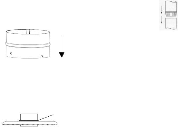
INSTALLING THE STOVE PIPE ADAPTER
After the appropriate flue outlet in the stove has been established the stove pipe adapter (included with every stove) must be installed so that standard stove pipe can be installed onto the stove.
Insert the end of the adapter with the four holes into the stove. These holes allow the adaptor to be attached to the stove’s internal collar, using the nuts and bolts provided with the stove. See figure 3.
DIRECTION INTO
THE STOVE
FIGURE3
The adaptor should be inserted into the stove until the bead on the adapter is flush with the top, back or side casting. Now the adaptor is ready to accept single or double walled stove pipe. See figure 4.
Each joint of chimney connector or stove pipe must be secured with at least three sheet metal screws to ensure that the sections do not seperate.
ADAPTOR BEAD
SHOULD BE FLUSH
WITH STOVE
FIGURE4
STOVE PIPE
CHIMNEY CONNECTOR
The chimney connector is a single walled pipe used to connect the stove to the chimney. For use with the F 3 CB the chimney connector MUST be 6” in diameter, with a minimum thickness of 24 gauge black steel.
Aluminum and Galvanized steel pipe is not acceptable for use with the F 3 CB. These materials cannot withstand the extreme temperatures of a wood fire and can give off toxic fumes when heated.
Each chimney connector or stove pipe section must be installed to the stove flue collar and to each other with the male (crimped) end toward the stove. See figure 5.
This prevents any amount of condensed or liquid creosote from running down the outside of the pipe or the stove top. All joints, including the flue collar connection must be secured with three sheet metal screws to ensure that the sections do not separate.
crimped end installed toward the stove
FIGURE5
For the best performance the chimney connector should be as short and direct as possible, with no more than two 90° elbows. The maximum horizontal run is 36” and a recommended total length of stove pipe should not exceed 10 feet. Always slope horizontal runs upward ¼” per foot toward the chimney.
No part of the chimney connector may pass through an attic or roof space, closet or other concealed space, or through a floor or ceiling. All sections of the chimney connectors must be accessible for cleaning. Where passage through a wall or partition of combustible construction is desired, the installation must conform with NFPA 211 or CAN/CSA-B365, and is also addressed in this manual.
DO NOT CONNECT THIS UNIT TO A CHIMNEY FLUE SERVICING ANOTHER APPLIANCE.
Do not use the connector pipe as a chimney.
5
CHIMNEY REQUIREMENTS
There are two types of chimneys suitable for the F 3 CB:
1.A codeapproved masonry chimney with a flue liner.
2.A prefabricated chimney complying with the requirements for Type HT (2100°F) chimneys per UL 103 or ULC S629.
The chimney size should not be less than the crosssectional area of the flue collar, and not more than three times greater than the cross-sectional area of the flue collar.
When selecting a chimney type and the location for the chimney in the house, keep this in mind: it is the chimney that makes the stove work, NOT the stove that makes the chimney work. This is because a chimney actually creates a suction, called “draft” which pulls air through the stove.
Several factors affect draft: chimney height, crosssectional area (size), and temperature of the chimney, as well as the proximity of surrounding trees or buildings.
As a result, a short masonry chimney on the exterior of a house will give the poorest performance. This is because it can be very difficult to warm the chimney thereby creating inadequate draft. In extremely cold northern areas it may be necessary to reline the chimney or extend its height to help establish draft.
Oppositely, a tall masonry chimney inside the house is easier to keep warm and will perform the best.
The following guidelines give the necessary chimney requirements based on the national code (ANSINFPA 211for the US. And CSA CAN-B365 for Canada). However, many local codes differ from the national code to take into account climate, altitude, or other factors. It is important that you check with your local building officials to find out what codes apply in your area before installing your new F 3 CB.
Masonry Chimneys
When installing the F 3 CB into a masonry chimney you must conform to all of the following guidelines:
·The masonry chimney must have a fireclay liner or equivalent, with a minimum thickness of 5/8” and must be installed with refractory mortar. There must be at least ½” air space between the flue liner and chimney wall.
·The fireclay flue liner must have a nominal size of 8” X 8”, and should not be larger than
8”X 12”. If a round fireclay liner is to be used it must have a minimum inside diameter of 6” and not larger than 8” in diameter. If a chimney with larger dimensions is to be used, it should be relined with an appropriate liner that is code approved.
·The masonry wall of the chimney, if brick or modular block, must be a minimum of 4” nominal thickness. A mountain or rubble stone wall must be at least 12” thick.
·A newly-built chimney must conform to local codes and in their absence must recognize national regulations.
·When using an existing chimney, it must be inspected by a professional licensed chimney sweep, fire official, or code officer, to ensure that the chimney is in proper working order.
·No other appliance can be vented into the same flue.
·An airtight clean-out door should be located at the base of the chimney.
Prefabricated Chimneys
If a prefabricated metal chimney is to be used it must be a chimney type that is tested and listed for use with solid fuel burning appliances. High Temperature (HT) Chimney Standard UL 103 for the U.S. and High Temperature Standard ULC S-629 for Canada.
6
The manufacturer’s installation instructions must be followed precisely. Always maintain the proper clearance to combustibles as established by the pipe manufacturer. This clearance is usually a minimum of 2”, although it may vary by manufacturer or for certain chimney components.
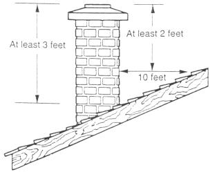
Chimney Height
Whether a masonry chimney or prefabricated metal chimney is used it must be the required height above the roof line.
The requirement is:
The chimney must be at least 3 feet higher than the highest point where it passes through the roof and at least 2 feet higher than the highest part of the roof or structure that is within 10 feet of the chimney, measured horizontally. See figure 6.
FIGURE6
Chimneys shorter than 14 feet may not provide adequate draft. This could result is smoke spilling into the room from the stove when loading the stove, or when the door is open. In addition, inadequate draft can cause back puffing, which is a build up of gases inside the firebox.
Other times, chimney height can create excessive draft which can cause high stove temperatures and short burn times. Excessive drafts can be corrected by installing a butterfly damper. If you suspect you have a draft problem, consult your dealer.
WALL PASS-THROUGHS
When your installation unavoidably requires the chimney connector to pass through a combustible wall to reach the chimney, always consult your local building officials, and be sure any materials to be used have been tested and listed for wall pass-throughs.
In the U.S.
The National Fire ProtectionAssociation’s publication, NFPA 211, Standard for Chimneys, Fireplaces, Vents and Solid Fuel Burning Appliances permits four methods for passing through a combustible wall. Before proceeding with any method be sure to consult with your local building officials to discuss any local code requirements.
Common Method
When passing through a combustible wall to a masonry chimney this method requires the removal of all combustible materials from at least 12” around the chimney connectors proposed location. With a 6” round liner the minimum area required would be 31” x 31” square.
The space is then filled with at least 12” of brick around a fireclay liner. Remember, the liner must be ASTM C35 or equivalent, with a minimum wall thickness of 5/8”.
It is important to remember to locate the pass-through at least 18” from the ceiling for proper clearance to combustibles.
It will be necessary to cut wall studs, install headers, and construct a sill frame to maintain the proper dimensions and to support the weight of the brick.
The bricks must be solid brick with a minimum of 3 ½ “ thick (4” nominal).
Refractory mortar must be used at the junction of the chimney and the pass-through liner. The pass-through liner must not penetrate the chimney liner beyond the inner surface of the chimney liner. Use extreme care when constructing the hole in the chimney liner, the tiles can shatter easily. See figure 7.
7
 Loading...