


GHGD
Johnson Controls GHGD, THGD, THJD, YHJD, YHJR Instruction Manual
...
835961-UIM-A-0112
R-410A OUTDOOR SPLIT-SYSTEM
HEAT PUMP
MODELS: 13 SEER & 14.5 SEER THG(D,F)/GHGD/THJ(D,F)/YHJ(D, F)/YHJ R/THJR SERIES
1.5 TO 5 TONS – 1 & 3 PHASE
INSTALLATION MANUAL
®
LIST OF SECTIONS
GENERAL . . . . . . . . . . . . . . . . . . . . . . . . . . . . . . . . . . . . . . . . . . . . . .1
SAFETY . . . . . . . . . . . . . . . . . . . . . . . . . . . . . . . . . . . . . . . . . . . . . . . .1
UNIT INSTALLATION . . . . . . . . . . . . . . . . . . . . . . . . . . . . . . . . . . . . .2
ORIFICE INSTALLATION . . . . . . . . . . . . . . . . . . . . . . . . . . . . . . . . . .5
TXV INSTALLATIONS . . . . . . . . . . . . . . . . . . . . . . . . . . . . . . . . . . . .5
EVACUATION . . . . . . . . . . . . . . . . . . . . . . . . . . . . . . . . . . . . . . . . . . .6
SYSTEM CHARGE . . . . . . . . . . . . . . . . . . . . . . . . . . . . . . . . . . . . . . 6
ELECTRICAL CONNECTIONS . . . . . . . . . . . . . . . . . . . . . . . . . . . . . 6
SYSTEM START-UP . . . . . . . . . . . . . . . . . . . . . . . . . . . . . . . . . . . . . 8
SYSTEM OPERATION . . . . . . . . . . . . . . . . . . . . . . . . . . . . . . . . . . . 10
INSTRUCTING THE OWNER . . . . . . . . . . . . . . . . . . . . . . . . . . . . . 12
WIRING DIAGRAM . . . . . . . . . . . . . . . . . . . . . . . . . . . . . . . . . . . . . 13
LIST OF FIGURES
Typical Installation with Required Clearances . . . . . . . . . . . . . . . . . . .2
Tubing Hanger . . . . . . . . . . . . . . . . . . . . . . . . . . . . . . . . . . . . . . . . . . .3
Underground Installation . . . . . . . . . . . . . . . . . . . . . . . . . . . . . . . . . . .3
Heat Protection . . . . . . . . . . . . . . . . . . . . . . . . . . . . . . . . . . . . . . . . . .4
Orifice Installation . . . . . . . . . . . . . . . . . . . . . . . . . . . . . . . . . . . . . . . . .5
Outdoor Unit Control Box - Single Phase . . . . . . . . . . . . . . . . . . . . . . .7
Outdoor Unit Control Box - Three Phase . . . . . . . . . . . . . . . . . . . . . . .7
Typical Field Wiring (Air Handler / Electrical Heat) (Single-Phase) . . .7
Typical Field Wiring (Air Handler / Electrical Heat) - (Three Phase) . .8
Heat Pump Flow Diagram . . . . . . . . . . . . . . . . . . . . . . . . . . . . . . . . . . 9
Time/Temp Control Module . . . . . . . . . . . . . . . . . . . . . . . . . . . . . . . . 9
Demand Defrost Control Module . . . . . . . . . . . . . . . . . . . . . . . . . . . . 9
Defrost Operation Curves . . . . . . . . . . . . . . . . . . . . . . . . . . . . . . . . . 11
Wiring Diagram - Single Phase (Demand Defrost) . . . . . . . . . . . . . . 13
Wiring Diagram - Single Phase (Time-Temp) . . . . . . . . . . . . . . . . . . 14
Wiring Diagram - Three Phase (Demand Defrost) . . . . . . . . . . . . . . 15
Wiring Diagram - Three Phase (Time-Temp) . . . . . . . . . . . . . . . . . . 16
LIST OF TABLES
R-410A Saturation Properties . . . . . . . . . . . . . . . . . . . . . . . . . . . . . . .9
TEST Input Functionality . . . . . . . . . . . . . . . . . . . . . . . . . . . . . . . . . .10
X/L Output Categories . . . . . . . . . . . . . . . . . . . . . . . . . . . . . . . . . . . 10
Defrost Initiate Curves . . . . . . . . . . . . . . . . . . . . . . . . . . . . . . . . . . . 11
SECTION I: GENERAL
The outdoor units are designed to be connected to a matching indoor
coil with sweat connect lines. Sweat connect units are factory charged
with refrigerant for a matching indoor coil plus 15 feet of field supplied
lines.
Matching indoor coils are available with a thermal expansion valve or
an orifice liquid feed sized for the most common usage. The orifice size
and/or refrigerant charge may need to be changed for some indoor-outdoor unit combinations, elevation differences, or total line lengths. Refer
to Application Data covering “General Piping Recommendations and
Refrigerant Line Length” (Part Number 247077).
SECTION II: SAFETY
This is a safety alert symbol. When you see this symbol on
labels or in manuals, be alert to the potential for personal
injury.
Understand and pay particular attention to the signal words DANGER,
WARNING, or CAUTION.
DANGER indicates an imminently hazardous situation, which, if not
avoided, will result in death or serious injury
.
WARNING indicates a potentially hazardous situation, which, if not
avoided, could result in death or serious injury
.
CAUTION indicates a potentially hazardous situation, which, if not
avoided may result in minor or moderate injury
. It is also used to
alert against unsafe practices and hazards involving only property damage.
INSPECTION
As soon as a unit is received, it should be inspected for possib le damage during transit. If damage is evident, the extent of the damage
should be noted on the carrier’s delivery receipt. A separate request for
inspection by the carrier’s agent should be made in writing. See Local
Distributor for more information.
Improper installation may create a condition where the operation of
the product could cause personal injury or property damage.
Improper installation, adjustment, alteration, service, or maintenance can cause injury or property damage. Refer to this manual
for assistance or for additional information, consult a qualified contractor, installer, or service agency.
This product must be installed in strict compliance with the
enclosed installation instructions and any applicable local, state,
and national codes including, but not limited to building, electrical,
and mechanical codes.
835961-UIM-A-0112
2 Johnson Controls Unitary Products
Requirements For Installing/Servicing R-410A Equipment
• Gauge sets, hoses, refrigerant containers, and recovery system
must be designed to handle the POE type oils, and the higher
pressures of R-410A.
• Manifold sets should be 800 psig high side and 250 psig low side
with 550 psig low side restart.
• All hoses must have a 700 psig service pressure rating.
• Leak detectors should be designed to detect HFC refrigerant.
• Recovery equipment (including refrigerant recovery containers)
must be specifically designed to handle R-410A.
• Do not use an R-22 TXV.
• A liquid-line filter drier is required on every unit.
LIMITATIONS
The unit should be installed in accordance with all National, State, and
Local Safety Codes and the limitations listed below:
1. Limitations for the indoor unit, coil, and appropriate accessories
must also be observed.
2. The outdoor unit must not be installed with any duct work in the air
stream. The outdoor fan is the propeller type and is not designed
to operate against any additional external static pressure.
3. The maximum and minimum conditions for operation must be
observed to assure a system that will give maximum performance
with minimum service.
4. The maximum allowable line length for this product is 75 feet.
SECTION III: UNIT INSTALLATION
LOCATION
Before starting the installation, select and check the suitability of the
location for both the indoor and outdoor unit. Observe all limitations and
clearance requirements.
The outdoor unit must have sufficient clearance for air entrance to the
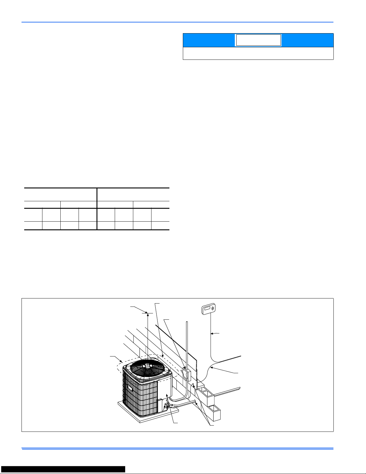
condenser coil, for air discharge, and for service access. See Figure 1.
If the unit is to be installed on a hot sun exposed roof or a black-topped
ground area, the unit should be raised sufficiently above the roof or
ground to avoid taking the accumulated layer of hot air into the outdoor
unit.
Provide an adequate structural support.
ADD-ON REPLACEMENT/RETROFIT
When this unit is being used as a replacement for an R-22 unit, it is
required that the outdoor unit, indoor coil, and metering device all be
replaced. The following steps should be performed in order to insure
proper system operation and performance. Line-set change out is also
recommended.
1. Change-out of the indoor coil to an approved R-410A coil/ condensing unit combination with the appropriate metering device.
2. Change-out of the line-set when replacing an R-22 unit with an
R410-A unit is highly recommended to reduce cross-contamination of oils and refrigerants.
3. If change-out of the line set is not practical, then the following precautions should be taken.
• Inspect the line set for kinks, sharp bends, or other restrictions,
and for corrosion.
• Determine if there are any low spots which might be serving as oil
traps.
• Flush the line set with a commercially available flush kit to
remove as much of the existing oil and contaminants as possible.
• Install a suction line filter-drier to trap any remaining contaminants, and remove after 50 hours of operation.
4. If the outdoor unit is being replaced due to a compressor burnout,
then installation of a 100% activated alumina suction-line filter
drier in the suction-line is required, in addition to the factory
installed liquid-line drier. Operate the system for 10 hours. Monitor
the suction drier pressure drop. If the pressure drop exceeds 3
psig, replace both the suction-line and liquid-line driers. After a
total of 10 hours run time where the suction-line pressure drop has
not exceeded 3 psig, replace the liquid line drier, and remove the
suction-line drier. Never leave a suction-line drier in the system
longer than 50 hours of run time.
AIR TEMPERATURE AT
OUTDOOR COIL, °F
AIR TEMPERATURE AT
INDOOR COIL, °F
Min. Max. Min. Max.
DB
Cool
DB
HeatDBCool
DB
Heat
WB
Cool
DB
Heat
WB
Cool
DB
Heat
50 -10 115 75 57
50
1
1. Operation below this temperature is permissible for a short period of
time, during morning warm-up.
72 80
For multiple unit installations, units must be spaced a minimum of
24 inches apart (coil face to coil face).
NOTICE
FIGURE 1: Typical Installation with Required Clearances
THERMOSTAT
SEAL OPENING(S) WITH
PERMAGUM OR EQUIVALENT
TO INDOOR COIL
TO FURNACE OR
AIR HANDLER
TERMINAL BLOCK
NEC CLASS 2 WIRING
NEC CLASS 1 WIRING
ALL OUTDOOR WIRING
MUST BE WEATHERPROOF.
CONTROL
ACCESS
PANEL
WEATHERPROOF
DISCONNECT
SWITCH
MINIMUM 18” SERVICE
ACCESS CLEARANCE
ON ONE SIDE
60” OVERHEAD
CLEARANCE
10” CLEARANCE
AROUND PERIMETER
NOTE:
835961-UIM-A-0112
Johnson Controls Unitary Products 3
GROUND INSTALLATION
The unit may be installed at ground level on a solid base that will not
shift or settle, causing strain on the refrigerant lines and possible leaks.
Maintain the clearances shown in Figure 1 and install the unit in a level
position.
Normal operating sound levels may be objectionable if the unit is placed
directly under windows of certain rooms (bedrooms, study, etc.).
Condensate will drain from beneath the coil of the outdoor unit during
the defrost cycle. Normally this condensate may be allowed to drain
directly on the ground.
Elevate the unit sufficiently to prevent any blockage of the air entrances
by snow in areas where there will be snow accumulation. Check the
local weather bureau for the expected snow accumulation in your area.
Isolate the unit from rain gutters to avoid any possible wash out of the
foundation.
ROOF INSTALLATION
When installing units on a roof, the structure must be capable of supporting the total weight of the unit, including a pad, lintels, rails, etc.,
which should be used to minimize the transmission of sound or vibration into the conditioned space.
UNIT PLACEMENT
1. Provide a base in the pre-determined location.
2. Remove the shipping carton and inspect for possible damage.
3. Compressor tie-down bolts should remain tightened.
4. Position the unit on the base provided.
LIQUID LINE FILTER-DRIER
The heat pumps have a solid core bi-flow filter/drier located on the liquid
line.
*As listed on the “Energy Guide yellow sticker on the unit.
PIPING CONNECTIONS
The outdoor unit must be connected to the indoor coil using field supplied refrigerant grade copper tubing that is internally clean and dry.
Units should be installed only with the tubing sizes for approved system
combinations as specified in Tabular Data Sheet. The charge given is
applicable for total tubing lengths up to 15 feet. See Application Data
Part Number 247077 for installing tubing of longer lengths and elevation
differences.
PRECAUTIONS DURING LINE INSTALLATION
1. Install the lines with as few bends as possible. Care must be taken
not to damage the couplings or kink the tubing. Use clean hard
drawn copper tubing where no appreciable amount of bending
around obstruction is necessary. If soft copper must be used, care
must be taken to avoid sharp bends which may cause a restriction.
2. The lines should be installed so that they will not obstruct service
access to the coil, air handling system, or filter.
3. Care must also be taken to isolate the refrigerant lines to minimize
noise transmission from the equipment to the structure.
4. The vapor line must be insulated with a minimum of 1/2" foam rubber insulation (Armaflex or equivalent). Liquid lines that will be
exposed to direct sunlight and/or high temperatures must also be
insulated.
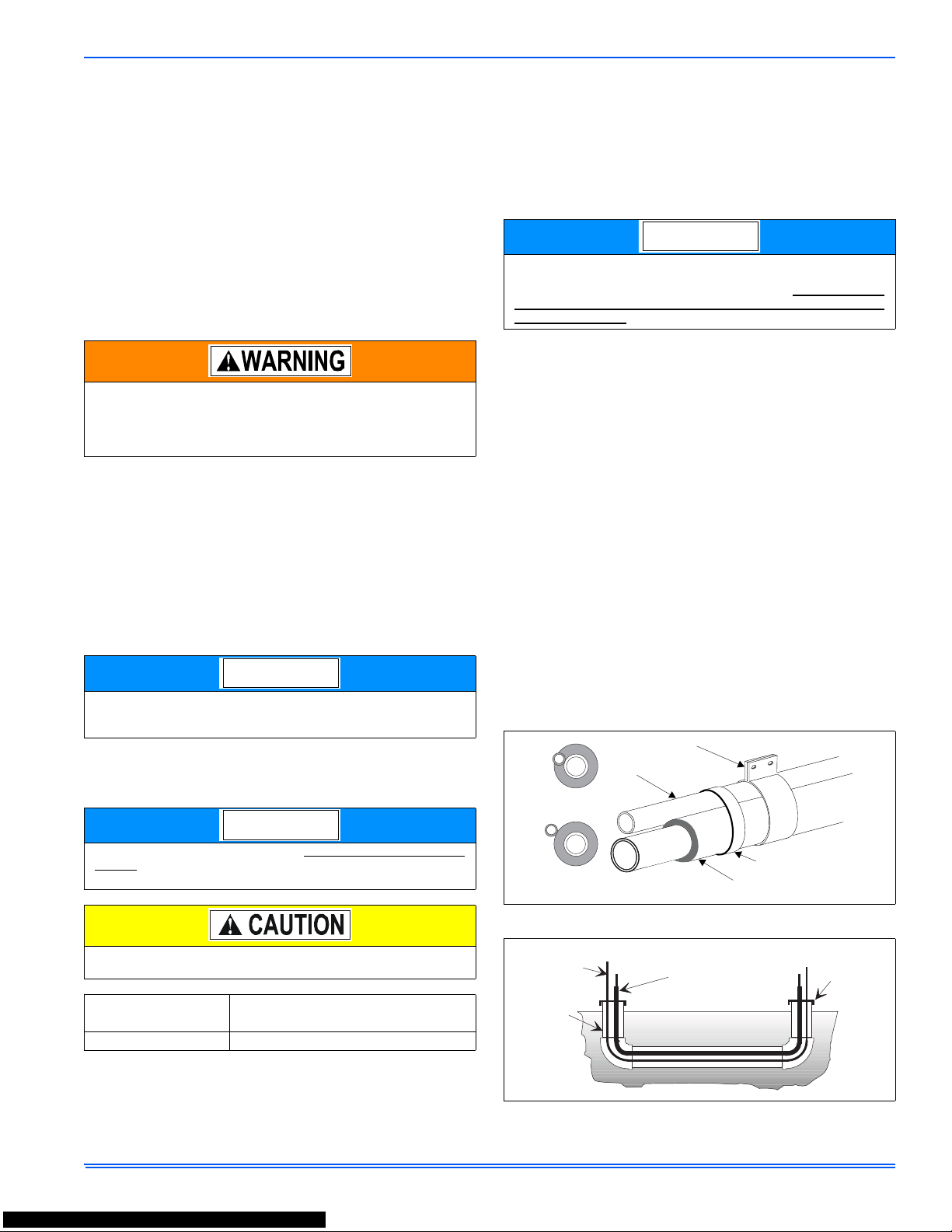
5. Tape and suspend the refrigerant lines as shown. DO NOT allow
tube metal-to-metal contact. See Figure 2.
6. Use PVC piping as a conduit for all underground installations as
shown in Figure 3. Buried lines should be kept as short as possible
to minimize the build up of liquid refrigerant in the vapor line during
long periods of shutdown.
7. Pack fiberglass insulation and a sealing material such as permagum around refrigerant lines where they penetrate a wall to reduce
vibration and to retain some flexibility.
8. See Form 247077 for additional piping information.
The outdoor unit should not be installed in an area where mud or
ice could cause personal injury. Remember that condensate will
drip from the unit coil during heat and defrost cycles and that this
condensate will freeze when the temperature of the outdoor air is
below 32°F.
Heat pumps will defrost periodically resulting in water drainage. The
unit should not be located where water drainage may freeze and
create a hazardous condition - such as sidewalks and steps.
Replacements for the liquid line drier must be exactly the same as
marked on the original factory drier. See Source 1 for O.E.M.
replacement driers.
Failure to do so or using a substitute drier or a granular type may
result in damage to the equipment.
Filter-Drier
Source 1 Part No.
Apply with Models
S1-52636219000 All
NOTICE
NOTICE
Using a larger than specified line size could result in oil return problems. Using too small a line will result in loss of capacity and other
problems caused by insufficient refrigerant flow. Slope horizontal
vapor lines at least 1" every 20 feet toward the outdoor unit to facilitate proper oil return.
FIGURE 2: Tubing Hanger
FIGURE 3: Underground Installation
NOTICE
Liquid
Line
Incorrect
Correct
Tape
Sheet Metal Hanger
Insulated Vapor Line
TO INDOOR COIL
TO O UT DO OR UNI T
LIQUID LINE
CAP
PVC
CONDUIT
INSULATED
VAPOR LINE
835961-UIM-A-0112
4 Johnson Controls Unitary Products
PRECAUTION S DUR IN G BRAZING OF LINES
All outdoor unit and evaporator coil connections are copper-to-copper
and should be brazed with a phosphorous-copper alloy material such
as Silfos-5 or equivalent. DO NOT use soft solder. The outdoor units
have reusable service valves on both the liquid and vapor connections.
The total system refrigerant charge is retained within the outdoor unit
during shipping and installation. The reusable service valves are provided to evacuate and charge per this instruction.
Serious service problems can be avoided by taking adequate precautions to assure an internally clean and dry system.
PRECAUTION S DUR IN G BRAZ I NG SERVICE VALVE
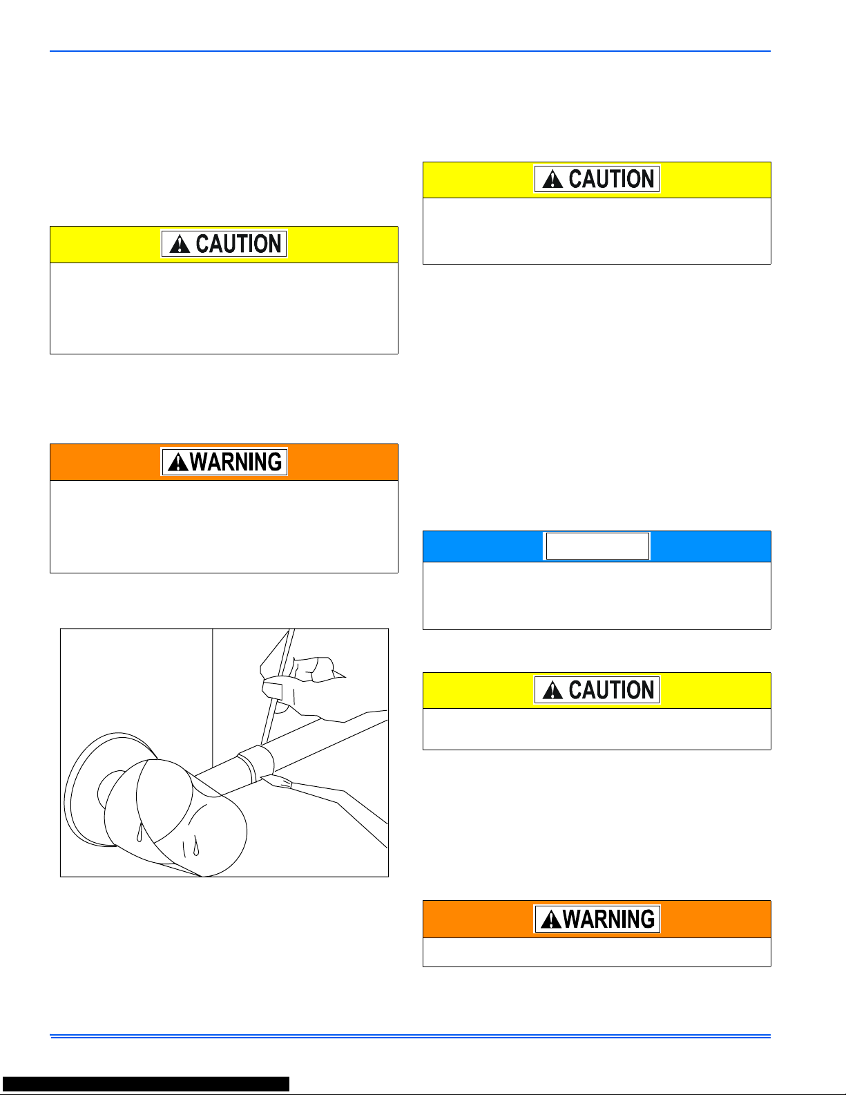
Precautions should be taken to prevent heat damage to service valve
by wrapping a wet rag around it as shown in Figure 4. Also, protect all
painted surfaces, insulation, and plastic base during brazing. After brazing cool joint with wet rag.
Valve can be opened by removing the plunger cap and fully inserting a
hex wrench into the stem and backing out counter-clockwise until valve
stem just touches the chamfered retaining wall.
Connect the refrigerant lines using the following procedure:
1. Remove the cap and Schrader core from both the liquid and vapor
service valve service ports at the outdoor unit. Connect low pressure nitrogen to the liquid line service port.
2. Braze the liquid line to the liquid valve at the outdoor unit. Be sure
to wrap the valve body with a wet rag. Allow the nitrogen to continue flowing. Refer to the Tabular Data Sheet for proper liquid line
sizing.
3. Go to “SECTION IV” or “SECTION V” for orifice or TXV Installation
depending on application.
4. Braze the liquid line to the evaporator liquid connection. Nitrogen
should be flowing through the evaporator coil.
5. Slide the grommet away from the vapor connection at the indoor
coil. Braze the vapor line to the evaporator vapor connection. After
the connection has cooled, slide the grommet back into original
position. Refer to the Tabular Data Sheet for proper vapor line sizing.
6. Protect the vapor valve with a wet rag and braze the vapor line
connection to the outdoor unit. The nitrogen flow should be exiting
the system from the vapor service port connection. After this connection has cooled, remove the nitrogen source from the liquid fitting service port.
7. Replace the Schrader core in the liquid and vapor valves.
8. Leak test all refrigerant piping connections including the service
port flare caps to be sure they are leak tight. DO NOT OVERTIGHTEN (between 40 and 60 inch - lbs. maximum).
9. Evacuate the vapor line, evaporator, and the liquid line to 500
microns or less.
10. Replace cap on service ports. Do not remove the flare caps from
the service ports except when necessary for servicing the system.
11. Release the refrigerant charge into the system. Open both the liquid and vapor valves by removing the plunger cap and with an
allen wrench back out counter-clockwise until valve stem just
touches the chamfered retaining wall. If the service valve is a ball
valve, use a cresent wrench to turn valve stem one-quarter turn
counterclockwise to open. Do not overturn or the valve stem may
break or become damaged. See “PRECAUTIONS DURING
BRAZING SERVICE VALVE”.
12. Replace plunger cap finger tight, then tighten an additional 1/12
turn (1/2 hex flat). Cap must be replaced to prevent leaks.
See "System Charge” section for checking and recording system
charge.
Dry nitrogen should always be supplied through the tubing while it
is being brazed, because the temperature is high enough to cause
oxidation of the copper unless an inert atmosphere is provided. The
flow of dry nitrogen should continue until the joint has cooled.
Always use a pressure regulator and safety valve to insure that only
low pressure dry nitrogen is introduced into the tubing. Only a small
flow is necessary to displace air and prevent oxidation.
This is not a backseating valve. The service access port has a
valve core. Opening or closing valve does not close service access
port.
If the valve stem is backed out past the chamfered retaining wall,
the O-ring can be damaged causing leakage or system pressure
could force the valve stem out of the valve body possibly causing
personal injury.
FIGURE 4: Heat Protection
Do not install any coil in a furnace which is to be operated during
the heating season without attaching the refrigerant lines to the coil.
The coil is under 30 to 35 psig inert gas pressure which must be
released to prevent excessive pressure build-up and possible coil
damage.
Line set and indoor coil can be pressurized to 250 psig with dry
nitrogen and leak tested with a bubble type leak detector. Then
release the nitrogen charge.
Do not use the system refrigerant in the outdoor unit to purge or
leak test.
Do not connect manifold gauges unless trouble is suspected.
Approximately 3/4 ounce of refrigerant will be lost each time a standard manifold gauge is connected.
Never attempt to repair any brazed connections while the system is
under pressure. Personal injury could result.
NOTICE
835961-UIM-A-0112
Johnson Controls Unitary Products 5
SECTION IV: ORIFICE INSTALLATION
Install Schrader Valve Core and Orifice as follows:
1. Relieve the holding charge by depressing the Schrader valve stem
located in the end of the liquid line. Cut the spundown copper to
allow installation of the suction line.
2. Slide indoor coil out of cabinet far enough to gain access to equalizer fitting on the suction line.
3. After holding charge is completely discharged remove black plastic cap on equalizer fitting.
4. Install Schrader Valve Core supplied with the outdoor unit into
equalizer fitting using a valve core tool.
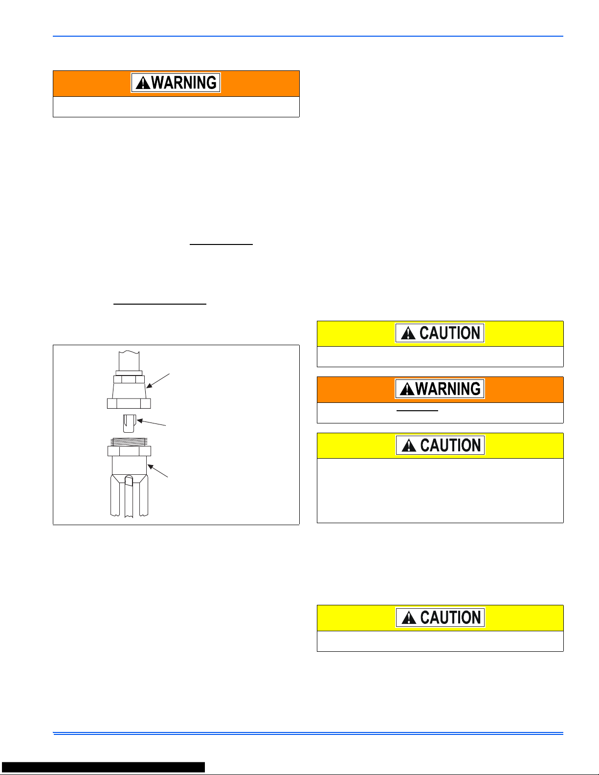
5. Loosen and remove the liquid line fitting from the orifice distributor
assembly. Note that the fitting has right hand threads
.
6. Install proper size orifice supplied with outdoor unit. Refer to supplied Tabular Data Sheet for specific orifice size and indoor coil
match up.
7. After orifice is installed reinstall the liquid line to the top of the orifice distributor assembly. Hand tighten and turn an additional 1/8
turn to seal. Do not over tighten fittings.
8. Leak test system.
9. Replace black plastic cap on equalizer fitting.
10. Slide indoor coil back into cabinet.
SECTION V: TXV INSTALLATIONS
For installations requiring a TXV, the following are the basic steps for
installation. For detailed instructions, refer to the Installation Instructions
accompanying the TXV kit.
Install TXV kit as follows:
1. Relieve the holding charge by depressing the Schrader valve stem
located in the end of the liquid line. Cut the spundown copper to
allow installation of the suction line.
2. After holding charge is completely discharged, loosen and remove
the Schrader cap seal.
3. Loosen and remove distributor cap seal.
4. Install the thermal expansion valve to the orifice distributor assembly with supplied fittings. Hand tighten and turn an additional 1/4
turn to seal. Do not overtighten fittings.
5. Install the liquid line to the top of the thermal expansion valve with
fitting supplied with the liquid line. Hand modify the liquid line to
align with casing opening. Hand tighten the liquid line and an additional 1/4 turn to seal.
6. Install the TXV equalizer line into the vapor line as follows:
a. Hand tighten the 1/4” SAE nut to the Schrader fitting and an
additional 1/3 turn to seal.
7. Install the TXV bulb to the vapor line near the equalizer line, using
the bulb clamp(s) furnished with the TXV assembly. Ensure the
bulb is making maximum contact.
a. Bulb should be installed on a horizontal run of the vapor line if
possible. On lines under 7/8" O.D. the bulb may be installed
on top of the line. With 7/8" O.D. and over, the bulb should be
installed at the position of about 2 or 10 o'clock.
b. If bulb installation is made on a vertical run, the bulb should
be located at least 16” (40.6 cm) from any bend, and on the
tubing sides opposite the plane of the bend. The bulb should
be positioned with the bulb tail at the top, so that the bulb acts
as a reservoir.
c. Bulb should be insulated using thermal insulation pro vided to
protect it from the effect of the surrounding ambient temperature. Cover completely to insulate from air-stream.
All connections to be brazed are copper-to-copper and should be
brazed with a phosphorous-copper alloy material such as Silfos-5 or
equivalent. DO NOT use soft solder.
Install the TXV bulb to the vapor line near the equalizer line, using the
two bulb clamps furnished with the TXV assembly. Ensure the bulb is
making maximum contact. Refer to TXV installation instruction for view
of bulb location.
Failure to install Schrader Valve Core on orifice applications could
result in total refrigerant loss of the system!
FIGURE 5: Orifice Installation
LIQUID LINE
SWIVEL COUPLING
(This fitting is a right-hand thread,
turn counter-clockwise to remove)
ORIFICE
DISTRIBUTOR
In all cases, mount the TXV bulb after vapor line is brazed and has
had sufficient time to cool.
Schrader valve core MUST NOT be installed with TXV installation.
Poor system performance or system failure could result.
Dry nitrogen should always be supplied through the tubing while it
is being brazed, because the temperature is high enough to cause
oxidation of the copper unless an inert atmosphere is provided. The
flow of dry nitrogen should continue until the joint has cooled.
Always use a pressure regulator and safety valve to insure that only
low pressure dry nitrogen is introduced into the tubing. Only a small
flow is necessary to displace air and prevent oxidation.
In all cases, mount the TXV bulb after vapor line is brazed and has
had sufficient time to cool.
 Loading...