


 Loading...
M9220-GGx-3
Proportional Electric Spring Return Actuators
Installation Instructions
Part No. 34-636-1697, Rev. B
Issued February 4, 2009
Supersedes June 20, 2006
Applications |
Installation |
The M9220-GGx-3 Proportional Electric Actuators are direct-mount, spring return electric actuators that operate on AC/DC 24V power. These bidirectional actuators do not require a damper linkage, and are easily installed on dampers with 1/2 to 3/4 in. or 12 to 19 mm round shafts, or 3/8 and 1/2 in. or
10, 12, and 14 mm square shafts using the standard shaft clamp included with the actuator. An optional M9220-600 Jackshaft Coupler Kit is available for 3/4 to 1-1/16 in. or 19 to 27 mm round shafts, or
5/8 and 3/4 in. or 16, 18, and 19 mm square shafts.
A single M9220-GGx-3 Series Proportional Electric Spring Return Actuator provides a running and spring return torque of 177 lb·in (20 N·m). Two or three like models mounted in tandem deliver twice or triple the torque (354 lb·in [40 N·m] or 531 lb·in [60 N·m]). Integral line voltage auxiliary switches are available on the GGC models to indicate end-stop position or to perform switching functions within the selected rotation range.
IMPORTANT: Use this M9220-GGx-3 Proportional Electric Spring Return Actuator only to control equipment under normal operating conditions. Where failure or malfunction of the electric actuator could lead to personal injury or property damage to the controlled equipment or other property, additional precautions must be designed into the control system. Incorporate and maintain other devices such as supervisory or alarm systems or safety or limit controls intended to warn of, or protect against, failure or malfunction of the electric actuator.
The M9220-GGx-3 Proportional Electric Spring Return Actuators mount directly to the surface in any convenient orientation using two M3 x 9.5 mm self-drilling sheet metal screws and the anti-rotation bracket (parts included with the actuator). No additional linkages or couplers are required. Electrical connections are color-coded and identified with numbers permanently marked on the actuator cable. A tag on the actuator cable identifies the electrical connections, and wiring details are also included on the actuator housing.
IMPORTANT: Do not install or use this
M9220 GGx-3 Proportional Electric Spring Return Actuator in or near environments where corrosive substances or vapors could be present. Exposure of the electric actuator to corrosive environments may damage the internal components of the device, and will void the warranty.
Parts Included
•proportional electric spring return actuator with coupler
•anti-rotation bracket
•manual override crank
•two M3 x 9.5 mm self-drilling sheet metal mounting screws
•two No. 10-32 x 9/16 in. thread-forming conduit screws
Special Tools Needed
•torque wrench with 3/8 in. (10 mm) socket
•digital voltmeter or M9000-200 Commissioning Tool
•flat blade screwdriver
M9220-GGx-3 Proportional Electric Spring Return Actuators Installation Instructions |
1 |

Dimensions |
|
|
|
|
4 |
|
|
|
|
(102) |
|
|
|
|
|
2 |
|
|
|
|
(51) |
|
|
|
1-19/32 |
1-19/32 |
|
3-3/16 |
|
|
(81) |
|||
(40) |
(40) |
1/8 |
||
3/4 |
||||
|
|
(3) |
(19) |
|
A |
|
2-3/16 |
|
|
|
|
|
||
1-19/32 |
|
(56) |
|
|
(40) |
|
|
|
|
1-1/16 |
|
|
|
|
(27) |
|
|
|
|
10-5/16 |
|
10 |
|
|
(262) |
|
(254) |
|
|
6-15/16 |
|
|
|
|
(176) |
|
|
|
|
1/4 (6.5) |
|
|
|
|
Mounting Hole |
|
|
|
|
(6 Locations) |
|
|
|
1-3/4 |
(44) |
1 |
2-3/16 |
(25)(56)
FIG:M9210_9220_dimen
Figure 1: M9220-GGx-3 Proportional Electric Spring Return Actuator Dimensions, in. (mm)
2 M9220-GGx-3 Proportional Electric Spring Return Actuators Installation Instructions

Accessories
Table 1: Accessories and Replacement Parts (Order Separately)
Code Number |
Description |
DMPR-KC0031 |
7 in. (178 mm) Blade Pin Extension (without Bracket) for Johnson Controls Direct-Mount Damper |
|
Applications |
M9000-200 |
Commissioning Tool that Provides a Control Signal to Drive 24 V On/Off, Floating, Proportional, |
|
and/or Resistive Electric Actuators |
|
|
M9000-153 |
Crank arm |
|
|
M9000-158 |
Tandem Mounting Kit used to Mount Two Models of M9210/20 Proportional Electric Spring Return |
|
Actuators |
|
|
M9000-170 |
Remote Mounting Kit, Horizontal. Kit includes Mounting Bracket, M9000-153 Crank Arm, Ball Joint, |
|
and Mounting Bolts |
|
|
M9000-171 |
Remote Mounting Kit, Vertical. Kit includes Mounting Bracket, M9000-153 Crank Arm, Ball Joint, and |
|
Mounting Bolts |
|
|
M9000-320 |
Weather Shield Enclosure - NEMA 3R enclosure for protecting a single M9210/20 from rain, sleet, or |
|
snow. |
|
|
M9000-604 |
Replacement Anti-rotation Bracket Kit (with Screws) for M9210-xxx-3 Series Proportional Electric |
|
Spring Return Actuators |
|
|
M9220-600 |
1 in. (25 mm) Jackshaft Coupler Kit (with Locking Clip) for Mounting M9210-xxx-3 Series Proportional |
|
Electric Spring Return Actuators on Dampers with 3/4 to 1-1/16 in. or 19 to 27 mm Round Shafts, or |
|
5/8 and 3/4 in. or 16, 18, and 19 mm Square Shafts |
|
|
M9220-601 |
Replacement Coupler Kit (with Locking Clip) for Mounting M9210-xxx-3 Series Proportional Electric |
|
Spring Return Actuators on Dampers with 1/2 to 3/4 in. or 12 to 19 mm Round Shafts, or 3/8 and 1/ |
|
2 in. or 10, 12, and 14 mm Square Shafts |
|
|
M9220-602 |
Replacement Locking Clips for M9210-xxx-3 Series Proportional Electric Spring Return Actuators |
|
(Five per Bag) |
|
|
M9220-603 |
Adjustable Stop Kit for M9210-xxx-3 Series Proportional Electric Spring Return Actuators |
|
|
M9220-604 |
Replacement Manual Override Cranks for M9210-xxx-3 Series Proportional Electric Spring Return |
|
Actuators (Five per Bag) |
|
|
M9220-610 |
Replacement Shaft Gripper, 10 mm Square Shaft with Locking Clip |
|
|
M9220-612 |
Replacement Shaft Gripper, 12 mm Square Shaft with Locking Clip |
|
|
M9220-614 |
Replacement Shaft Gripper, 14 mm Square Shaft with Locking Clip |
|
|
1.Furnished with the damper and may be ordered separately.
Mounting
The M9220-GGx-3 Proportional Electric Spring Return Actuators can be easily installed on dampers with 1/ 2 to 3/4 in. or 12 to 19 mm round shafts, or 3/8 and 1/ 2 in. or 10, 12, and 14 mm square shafts. An M9220600 Jackshaft Coupler Kit is available for 3/4 to 11/
16 in. or 19 to 27 mm round shafts, or 5/8 and 3/4 in. or 16, 18, and 19 mm square shafts; see Table 1 for more details. If the damper shaft extends less than 3-19/32 in. (91 mm), see the Removable Coupler section for further instructions. If the damper shaft extends less than 1-5/32 in. (29 mm), install an extension recommended by the damper manufacturer.
M9220-GGx-3 Proportional Electric Spring Return Actuators Installation Instructions |
3 |
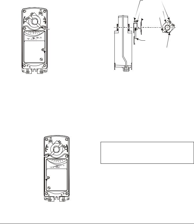
Counterclockwise (CCW) Spring Return Direction – Clockwise (CW) Powered Operation
For CCW spring return direction, mount the actuator to the damper shaft so that Side A of the actuator is away from the damper as illustrated in Figure 2. With power applied, the actuator drives CW from the 0° position, and spring returns CCW.
Side A: CCW Spring Return Direction
A

 Auxiliary Switch
Adjuster Located on the Right
|
|
|
Pointer Showing |
90 70 |
60 50 40 30 20 |
-5 |
Actuator in the |
80 |
|
10 |
|
Spring Return
Position
 Manual
Override
FIG:sidea
Figure 2: Side A of Actuator
Clockwise (CW) Spring Return Direction – Counterclockwise (CCW) Powered Operation
To change the spring return direction to CW, mount the actuator to the damper shaft so that Side B of the actuator is away from the damper as illustrated in Figure 3. With power applied, the actuator now drives CCW from the 0° position, and spring returns CW.
Side B: CW Spring Return Direction
B
Auxiliary Switch 

Adjuster Located
on the Left
Pointer Showing |
|
|
|
|
|
|
|
|
Actuator in the |
|
20 |
|
|
|
|
70 |
80 |
|
|
10 |
|
|
|
|
|
|
Spring Return |
-5 |
|
30 |
40 |
50 |
60 |
|
90 |
|
|
|
|
|
|
|
|
Position
Manual
Override
FIG:sideb
Figure 3: Side B of Actuator
Removable Coupler
The coupler may be installed on either side of the output hub. If the damper shaft is less than 3-19/32 in. (91 mm) long, insert the coupler in the face of the actuator closest to the damper. If the damper shaft is shorter than 1-5/32 in. (29 mm) long, a shaft extension is required to mount the actuator.
U-Bolt Nut
and Washer
(Qty Two)
 Shaft Coupler
 Pointer
U-Bolt 

 Locking Clip
Assembled View
of Coupler
Subassembly
FIG:chpos
Figure 4: Changing the Position of the Coupler
To change the position of the coupler, see Figure 4 and proceed as follows:
1.Mount the coupler on either Side A or Side B of the actuator, as determined by the shaft length.
2.Snap the locking clip securely into the coupler retention groove to retain the coupler.
Manual Override
Use only the supplied manual override crank to reposition the actuator hub when using the manual override feature.
IMPORTANT: Applying excessive torque to the manual override or running the manual override with a power tool may damage the internal components of the actuator and cause premature failure.
To reposition the actuator hub, proceed as follows:
1.De-energize the actuator.
2.Insert the hex end of the manual override crank into the manual override adjustment point on the face of the actuator.
3.Rotate the manual override crank in the direction indicated by the arrow on the label.
4 M9220-GGx-3 Proportional Electric Spring Return Actuators Installation Instructions
Loading...