


 Loading...
Product/Technical Bulletin |
A419 |
Issue Date |
August 13, 2014 |
A419 Series Electronic Temperature Controls with Display and NEMA 1 or NEMA 4X Watertight Enclosures
The A419 series controls are single-stage, electronic temperature controls with a Single-Pole, Double-Throw (SPDT) output relay. They feature a lockable front-panel touchpad for setup and adjustment, and an LCD for viewing the temperature and status of other functions. An LED indicates the controls’ output relay On/Off status. The A419 controls are available in 24 VAC or 120/240 VAC powered models.
The A419 controls have heating and cooling modes, adjustable setpoint and differential, an adjustable anti-short cycle delay, and a temperature offset function. The setpoint range is -30 to 212°F
(-34 to 100°C). The controls feature remote sensing capability and interchangeable sensors. The
A419 controls are available in either NEMA 1, high-impact plastic enclosure suitable for surface or DIN rail mounting or NEMA 4X watertight, corrosion-resistant surface-mount enclosures.
Figure 1: A419 Temperature Control with NEMA 1 Enclosure and A99 Temperature Sensor
|
Features and Benefits |
|
|
|
Easy-to-Read Front-Panel |
Displays the sensed temperature and control-function |
|
|
Liquid Crystal Display |
status clearly; custom icons on the display indicate the |
|
|
|
control and system status at a glance |
|
|
Wide Temperature Differential Adjustment |
Allows the user to set a precise (1F° or C°) temperature |
|
|
Range (1 to 30F° or C°) |
differential from 1 to 30F° or C°; providing a much |
|
|
|
tighter differential than electromechanical controls |
|
|
Adjustable Anti-Short Cycle Delay |
Ensures that the output relay remains off for a user-set |
|
|
(0 to 12 Minutes in 1-Minute Increments) |
time delay, which helps avoid hard starts, nuisance |
|
|
|
overload outages, and unnecessary equipment wear |
|
|
Switch-Activated Temperature Offset |
Allows the user to shift the cut-in and cutout setpoints |
|
|
Function |
by an adjustable offset based on the status of a |
|
|
|
user-installed, external switch, such as a time clock |
|
|
High-Impact, Thermoplastic NEMA 1 or |
Increase application options, allowing surface and |
|
|
NEMA 4X Watertight, Corrosion-Resistant |
snap-fit DIN rail mount, or Watertight surface mount |
|
|
Enclosures |
|
|
|
Lockable Front Panel Touchpad |
Allows easy set up and adjustment of the A419 control |
|
|
|
setpoint, differential, and other functions; a concealed |
|
|
|
jumper locks the touchpad, and deters unauthorized |
|
|
|
adjustment of the control settings |
|
|
Lowand Line-Voltage Models |
Provide options for most refrigeration and HVAC |
|
|
|
control-voltage applications |
|
|
|
|
|
|
|
|
|
© 2014 Johnson Controls, Inc. |
1 |
||
Code No. LIT-125188 |
www.johnsoncontrols.com |
||

Application
IMPORTANT: The A419 Series Temperature Controls are intended to control equipment under normal operating conditions. Where failure or malfunction of an A419 Series Control could lead to an abnormal operating condition that could cause personal injury or damage to the equipment or other property, other devices (limit or safety controls) or systems (alarm or supervisory) intended to warn of or protect against failure or malfunction of the A419 Series Control must be incorporated into and maintained as part of the control system.
The A419 Electronic Temperature Control can be used to control a wide variety of single-stage refrigeration or HVAC equipment. Typical applications include:
•retail store display freezers and reach-in coolers
•supermarket display cases for produce/meats
•retail store walk-in coolers and freezers
•boiler operating control (used as a thermostat)
•condenser fan cycling or staging
•cooling tower pump and fan control
•space and return air temperature control
FCC Compliance
This device complies with Part 15 of the FCC Rules. Operation is subject to the following two conditions:
(1) this device may not cause harmful interference, and (2) this device must accept any interference that may cause undesired operation.
This equipment has been tested and found to comply with the limits for a Class A digital device pursuant to Part 15 of FCC rules. These limits are designed to provide reasonable protection against harmful interference when this equipment is operated in a commercial environment. This equipment generates, uses, and can radiate radio frequency energy and, if not installed and used in accordance with the instruction manual, may cause harmful interference to radio communications. Operation of this equipment in a residential area may cause harmful interference, in which case the users will be required to correct the interference at their own expense.
Canadian Compliance Statement
Dimensions
9/64 |
|
2-3/8 |
|
||
(3.7) |
|
(61) |
1/2 |
|
|
5 |
(13) |
DIN |
|
|
|
MENU |
(127) |
|
2-15/16 |
Rail |
|
|
|
|
||
(75) |
|
|
4 |
|
|
|
|
|
|
|
(102) |
1-9/16 |
7/16 |
2-3/8 |
|
(40) |
(11) |
(61) |
|
|
Sensor |
|
2-3/8 |
|
2 |
|
|
1/4 |
7/8 |
(61) |
|
(50) |
|
||
(6) |
|
(22) |
|
|
|
7/8 |
(1/2 in. Trade Size) |
|
|
(22) |
Conduit Hole |
Figure 2: A419 Temperature Control with NEMA 1 Enclosure, Dimensions, in./(mm)
2-1/4 |
1-1/16 |
(56) |
(27) |
|
1-3/4 |
|
(44) |
A419 |
|
|
6-5/8 |
MENU |
(168) |
|
|
|
6-1/8 |
|
(155) |
2-13/16 |
|
(71) |
Position the A99 sensor |
|
in the bracket at the bottom of |
|
the A419 NEMA 4X enclosure. |
|
2-13/16 |
|
(71) |
Figure 3: A419 Temperature Control with NEMA 4X Watertight, Corrosion-resistant, Enclosure, Dimensions, in./(mm)
This digital apparatus does not exceed the Class A limits for radio noise emissions from digital apparatus set out in the Radio Interference Regulations of the Canadian Department of Communications.
2A419 Series Electronic Temperature Controls with Display and NEMA 1 or NEMA 4X Watertight Enclosures Product/Technical Bulletin
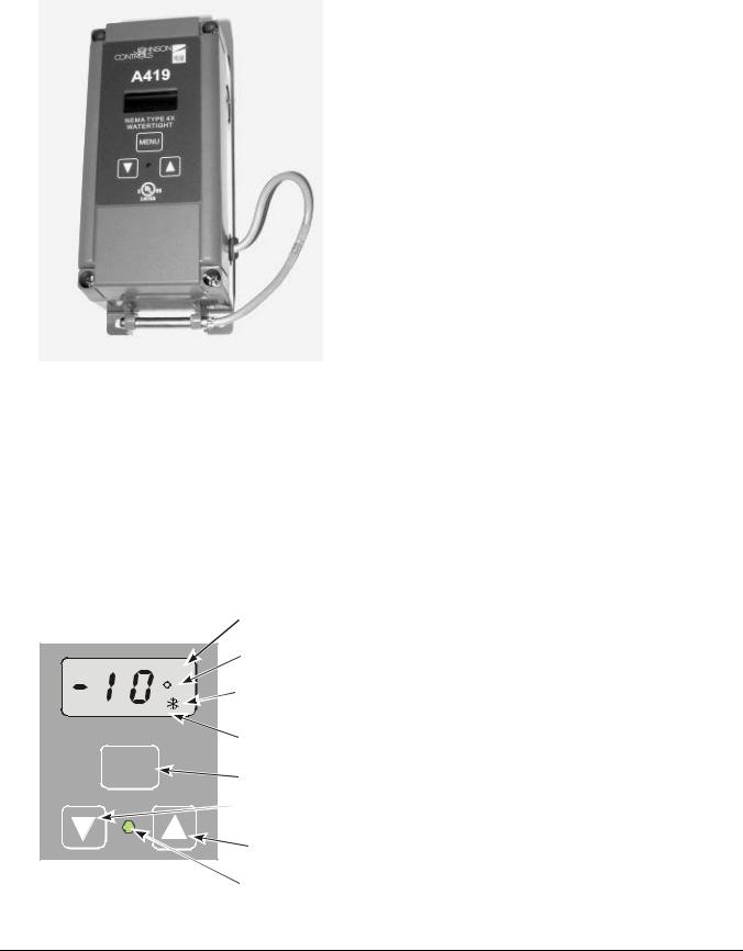
Figure 4: A419 Temperature Control with NEMA 4X Enclosure and A99 Temperature Sensor
Operation Overview
The A419 control’s front-panel, LCD, LED, and the A419 control functions are described below. See the Adjustments section for instructions on setting up and adjusting the A419 control.
A419 Control Front-Panel
The front panel of the A419 control has a three-button touchpad and LCD for adjusting control function values, and an LED indicator that displays the On/Off status of the SPDT output relay. See Figure 5.
|
Temperature |
|
|
Offset Indicator |
|
|
Temperature |
|
BIN |
Units Indicator |
|
F |
Operating Mode |
|
|
Indicator |
|
|
Liquid Crystal |
|
MENU |
Display |
|
MENU Button |
||
|
||
|
DOWN Arrow |
|
|
Button |
|
|
UP Arrow |
|
|
Button |
|
|
Output Relay |
|
|
Status Indicator |
|
|
LED |
Liquid Crystal Display
During normal operation, the LCD displays the temperature at the sensor, the units of temperature (°F or °C), and an icon indicating if the control is set for Heating ( ) or Cooling (
 ) mode. The LCD also displays BIN if the Temperature Offset function is activated. See Figure 5.
During control set up or adjustment, the LCD displays the control functions and their values (settings). After 30 seconds of inactivity, the display returns to the sensed-temperature display. See the Adjustments section to adjust the control setting.
Output Relay Status Indicator LED
A green LED on the control’s front panel illuminates when the SPDT output relay is energized and the Normally Open (N.O.) contacts are closed.
See Figure 5.
A419 Control Definitions
Cut-in is the temperature at which the N.O. contacts on the SPDT output relay close.
Cutout is the temperature at which the N.O contacts on the SPDT output relay open.
A419 Functions Set at the Front-Panel
Setpoint (SP) establishes the temperature value that energizes or de-energizes the output relay, depending on the user selected mode of operation. The control may be set either to cut in or to cut out at Setpoint. See the
Cooling/Heating and Setpoint Modes. The Setpoint range is -30 to 212°F (-34 to 100°C).
If Setpoint mode is Cut-in, Setpoint is the temperature value that closes the N.O. contacts. If Setpoint mode is Cutout, Setpoint is the temperature value that opens the N.O. contacts. See Figure 7 and Figure 8.
Differential (dIF) establishes the difference in temperature (in F° or C°) between the cut-in and cutout values. The differential is set relative to Setpoint and may be set from 1 to 30F° or C°. See Figure 7 and Figure 8.
Anti-Short Cycle Delay (ASd) establishes the minimum time that the N.O. contacts remains open (after reaching cutout) before closing again. The delay overrides any Load Demand and does not allow the N.O. contacts to close until the set time-delay value has elapsed. See Figure 6. When the delay is activated, the LCD alternately flashes the sensor temperature and ASd. The delay may be set for 0 to 12 minutes in 1-minute increments.
Figure 5: A419 Control Front-Panel with Display
A419 Series Electronic Temperature Controls with Display and NEMA 1 or NEMA 4X Watertight Enclosures Product/Technical Bulletin 3
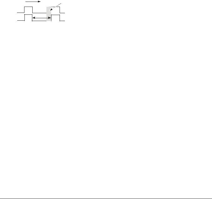
For example, if the anti-short cycle delay is set for 7 minutes, the A419 control will not restart the equipment for 7 minutes after the equipment has cut out, even if the cut-in temperature value is reached
during the delay. If the temperature reaches the cut-in value during the delay period, the display flashes between the sensed temperature and ASd, indicating that the next On-cycle is being delayed. After the set delay time has elapsed, the A419 control returns to normal operation, restarts the equipment (if cut-in has been reached), ASd stops flashing, and the LCD reverts to the normal operating display.
Note: Any interruption in supply power to the A419 control activates the anti-short cycle delay.
Time |
|
Load Demand |
|
On |
Overridden |
Off |
Load Demand |
|
|
On |
|
Off |
Output Status |
|
|
Anti-short |
|
|
|
|
|
Cycle Delay |
|
Figure 6: Anti-short Cycle Delay
Sensor Failure Operation (SF) establishes how the A419 control operates the equipment in the event of a sensor or sensor-wiring failure. The A419 control may be set to run the equipment continuously or to shut it down if the sensor or sensor wire fails. When a failure is detected the LCD flashes SF alternately with OP if the sensor circuit is open, or SF and SH if the sensor circuit is shorted. The control implements a 1-minute delay before initiating a failure response to allow for verification of the failure condition and to avoid nuisance failure indications.
Temperature Units establishes the units of temperature (F° or C°) displayed on the LCD.
Temperature Offset (OFS) establishes the value of setpoint-shift (in F° or C°) applied to Setpoint (and Differential) when a (user-installed) circuit is closed between the binary input (BIN) and common (COM) terminals. The offset value may be set from 0 to 50F° or C°.
The Temperature Offset function is used to reset the Heating Setpoint to a lower temperature (secondary) setpoint or reset the Cooling Setpoint to a higher temperature (secondary) setpoint by the temperature value set in Temperature Offset.
The BIN and COM terminals may be connected to a (user-supplied) external switching device, such as a time clock, that has a set of Single-Pole, Single-Throw (SPST) contacts. Closing a circuit between the BIN and COM terminals activates the Temperature Offset. See Wiring.
This function enables the control to alternate between two temperature setpoints based on the position of the binary input switch. The difference between the primary and secondary setpoints (in F° or C°) is set in the Temperature Offset function (OFS) using the touchpad. See Setting Other Functions.
Table 1 shows an example of Temperature Offset.
Table 1: Temperature Offset Example
Mode of |
Setpoint |
Temperature |
Secondary |
|
Operation |
Offset Value |
Setpoint* |
||
|
||||
Cooling |
70° |
8° |
78° |
|
Heating |
70° |
8° |
62° |
*Setpoint when circuit between binary input terminals (BIN and COM) is closed
When the circuit is closed between the binary input (BIN) common (COM) terminals, the offset function is enabled and the A419 control cycles on the secondary setpoints. BIN is displayed on the LCD above the °F or °C symbol when the offset is enabled. See Figure 5.
A419 Control Functions Set by Jumper Position
For instructions on positioning jumpers, see
Positioning the Jumpers in the Adjustments section. See Figure 12 and Figure 13.
Touchpad Lock: The jumper at P5 establishes whether the touchpad is locked or unlocked. Locking the touchpad deters accidental or unauthorized changes to all of the function parameters.
Heating/Cooling Mode is established by positioning the jumper on the top two pins of the P4 jumper. See Figure 13.
Setpoint Mode: Removing or installing the lower jumper at P4 establishes whether Setpoint is the cut-in temperature or cutout temperature. See Figure 13.
Cooling/Heating and Setpoint Modes
The A419 control may be in four operating modes:
Cooling/Cut-in, Cooling/Cutout, Heating/Cut-in, and
Heating/Cutout. Position the jumpers located on the circuit board under the A419 control cover to set the desired mode of operation. See Positioning the Jumpers.
In Cooling/Cut-in mode the differential is below Setpoint. The output relay energizes and the LED illuminates when the temperature rises to Setpoint. When the temperature drops to Setpoint minus the differential value, the relay and LED de-energize.
4A419 Series Electronic Temperature Controls with Display and NEMA 1 or NEMA 4X Watertight Enclosures Product/Technical Bulletin
Loading...