


 Loading...
INSTALLATION
MANUAL
CONTENTS
GENERAL . . . . . . . . . . . . . . . . . . . . . . . . . . . . . . . . 4 SAFETY CONSIDERATIONS . . . . . . . . . . . . . . . . . 4 INSPECTION. . . . . . . . . . . . . . . . . . . . . . . . . . . . . . 4 REFERENCE. . . . . . . . . . . . . . . . . . . . . . . . . . . . . . 4 RENEWAL PARTS . . . . . . . . . . . . . . . . . . . . . . . . . 4 APPROVALS . . . . . . . . . . . . . . . . . . . . . . . . . . . . . 4 PRODUCT NOMENCLATURE . . . . . . . . . . . . . . . . 5 INSTALLATION . . . . . . . . . . . . . . . . . . . . . . . . . . . 6 OPERATION . . . . . . . . . . . . . . . . . . . . . . . . . . . . . 31 START-UP (COOLING) . . . . . . . . . . . . . . . . . . . . 35 TROUBLESHOOTING . . . . . . . . . . . . . . . . . . . . . 35 MAINTENANCE . . . . . . . . . . . . . . . . . . . . . . . . . . 38
See the following page for a complete Table of Contents.
NOTES, CAUTIONS AND WARNINGS
The installer should pay particular attention to the words: NOTE, CAUTION, and WARNING. Notes are intended to clarify or make the installation easier. Cautions are given to prevent equipment damage. Warnings are given to alert installer that personal injury and/or equipment damage may result if installation procedure is not handled properly.
CAUTION: READ ALL SAFETY GUIDES BEFORE YOU
BEGIN TO INSTALL YOUR UNIT.
SAVE THIS MANUAL
SUNLINE 2000™
SINGLE PACKAGE HEAT PUMP
BQ 036, 048 & 060
EXPORT ONLY
ISO 9001
Certified Quality
Management System
364985-XIM-B-0508

364985-XIM-B-0508
TABLE OF CONTENTS
GENERAL . . . . . . . . . . . . . . . . . . . . . . . . . . . . . . . . . 4 SAFETY CONSIDERATIONS . . . . . . . . . . . . . . . . . . 4 INSPECTION . . . . . . . . . . . . . . . . . . . . . . . . . . . . . . . 4 REFERENCE . . . . . . . . . . . . . . . . . . . . . . . . . . . . . . 4 RENEWAL PARTS . . . . . . . . . . . . . . . . . . . . . . . . . . 4 APPROVALS . . . . . . . . . . . . . . . . . . . . . . . . . . . . . . 4 PRODUCT NOMENCLATURE . . . . . . . . . . . . . . . . . 5 INSTALLATION . . . . . . . . . . . . . . . . . . . . . . . . . . . . 6
INSTALLATION SAFETY INFORMATION: . . . . . . . . 6 LIMITATIONS . . . . . . . . . . . . . . . . . . . . . . . . . . . . . . . 6 LOCATION . . . . . . . . . . . . . . . . . . . . . . . . . . . . . . . . . 6 RIGGING AND HANDLING . . . . . . . . . . . . . . . . . . . . 7 CLEARANCES . . . . . . . . . . . . . . . . . . . . . . . . . . . . . . 7 DUCTWORK . . . . . . . . . . . . . . . . . . . . . . . . . . . . . . . . 7 CONDENSATE DRAIN . . . . . . . . . . . . . . . . . . . . . . . . 7 COMPRESSORS . . . . . . . . . . . . . . . . . . . . . . . . . . . . 8 FILTERS . . . . . . . . . . . . . . . . . . . . . . . . . . . . . . . . . . . 8 SERVICE ACCESS . . . . . . . . . . . . . . . . . . . . . . . . . . 8 THERMOSTAT . . . . . . . . . . . . . . . . . . . . . . . . . . . . . 10 POWER AND CONTROL WIRING . . . . . . . . . . . . . . 10 OPTIONS/ACCESSORIES . . . . . . . . . . . . . . . . . . . . 10
ELECTRIC HEAT . . . . . . . . . . . . . . . . . . . . . . . . . . . . 10
ECONOMIZER/MOTORIZED DAMPER AND
RAIN HOOD . . . . . . . . . . . . . . . . . . . . . . . . . . . . . . . 11
POWER EXHAUST/BAROMETRIC RELIEF
DAMPER AND RAIN HOOD . . . . . . . . . . . . . . . . . . . 11
ECONOMIZER AND POWER EXHAUST DAMPER SET POINT ADJUSTMENTS AND
INFORMATION . . . . . . . . . . . . . . . . . . . . . . . . . . . . 11
MINIMUM POSITION ADJUSTMENT . . . . . . . . . . . . 12 ENTHALPY SET POINT ADJUSTMENT . . . . . . . . . . 12
POWER EXHAUST DAMPER SETPOINT (WITH
OR WITHOUT POWER EXHAUST) . . . . . . . . . . . . . 12 INDOOR AIR QUALITY . . . . . . . . . . . . . . . . . . . . . . . 12
PHASING . . . . . . . . . . . . . . . . . . . . . . . . . . . . . . . . . 30 SUPPLY AIR BLOWERS . . . . . . . . . . . . . . . . . . . . . 30 CHECKING SUPPLY AIR CFM . . . . . . . . . . . . . . . . 30
OPERATION . . . . . . . . . . . . . . . . . . . . . . . . . . . . . . 31
SEQUENCE OF OPERATIONS OVERVIEW . . . . . . 31
COOLING SEQUENCE OF OPERATION . . . . . . . . 31
CONTINUOUS BLOWER . . . . . . . . . . . . . . . . . . . . . . 31 INTERMITTENT BLOWER . . . . . . . . . . . . . . . . . . . . 31 NO OUTDOOR AIR OPTIONS . . . . . . . . . . . . . . . . . 31
ECONOMIZER WITH SINGLE ENTHALPY
SENSOR - . . . . . . . . . . . . . . . . . . . . . . . . . . . . . . . . . 32
ECONOMIZER WITH DUAL ENTHALPY
SENSORS - . . . . . . . . . . . . . . . . . . . . . . . . . . . . . . . 32
ECONOMIZER (SINGLE OR DUAL) WITH POWER EXHAUST - . . . . . . . . . . . . . . . . . . . . . . . . . . . . . . . . 32
MOTORIZED OUTDOOR AIR DAMPERS - . . . . . . . 32
COOLING OPERATION ERRORS . . . . . . . . . . . . . 32
HIGH-PRESSURE LIMIT SWITCH . . . . . . . . . . . . . . 32 LOW-PRESSURE LIMIT SWITCH . . . . . . . . . . . . . . . 32 FREEZESTAT . . . . . . . . . . . . . . . . . . . . . . . . . . . . . . 32 LOW AMBIENT COOLING . . . . . . . . . . . . . . . . . . . . . 33
SAFETY CONTROLS . . . . . . . . . . . . . . . . . . . . . . . 33 COMPRESSOR PROTECTION . . . . . . . . . . . . . . . 33 FLASH CODES . . . . . . . . . . . . . . . . . . . . . . . . . . . . 33 RESET . . . . . . . . . . . . . . . . . . . . . . . . . . . . . . . . . . . 33 HEATING SEQUENCE OF OPERATIONS . . . . . . . 33
WITH OR WITHOUT ELECTRIC HEAT . . . . . . . . . . . 33 DEFROST MODE . . . . . . . . . . . . . . . . . . . . . . . . . . . 34 FORCED DEFROST . . . . . . . . . . . . . . . . . . . . . . . . . 34
SAFETY CONTROLS . . . . . . . . . . . . . . . . . . . . . . . 34 HEAT ANTICIPATOR SETPOINTS . . . . . . . . . . . . . 34
START-UP (COOLING) . . . . . . . . . . . . . . . . . . . . . 35
PRESTART CHECK LIST . . . . . . . . . . . . . . . . . . . . 35 OPERATING INSTRUCTIONS . . . . . . . . . . . . . . . . 35 POST START CHECK LIST . . . . . . . . . . . . . . . . . . 35 SHUT DOWN . . . . . . . . . . . . . . . . . . . . . . . . . . . . . . 35
TROUBLESHOOTING . . . . . . . . . . . . . . . . . . . . . . 35
COOLING TROUBLESHOOTING GUIDE . . . . . . . . 35 UNIT FLASH CODES . . . . . . . . . . . . . . . . . . . . . . . 37
MAINTENANCE . . . . . . . . . . . . . . . . . . . . . . . . . . . 38
NORMAL MAINTENANCE . . . . . . . . . . . . . . . . . . . 38 FILTERS . . . . . . . . . . . . . . . . . . . . . . . . . . . . . . . . . 38 MOTORS . . . . . . . . . . . . . . . . . . . . . . . . . . . . . . . . . 38 OUTDOOR COIL . . . . . . . . . . . . . . . . . . . . . . . . . . . 38
2 |
Johnson Controls Unitary Products |

364985-XIM-B-0508
|
LIST OF FIGURES |
|
Fig. # |
Pg. # |
|
1 |
RECOMMENDED DRAIN PIPING . . . . . . . . . . . . |
. . . . 7 |
2 |
COMPRESSOR RESTRAINING BRACKET . . . . |
. . . . 8 |
3 |
TYPICAL FIELD POWER & CONTROL WIRING |
. . . . 9 |
4 |
ENTHALPY SETPOINT ADJUSTMENT . . . . . . . |
. . . 13 |
5 |
HONEYWELL ECONOMIZER CONTROL W7212 |
. . . 13 |
6 |
FOUR AND SIX POINT LOADING . . . . . . . . . . . . |
. . . 14 |
7 |
UNIT DIMENSIONS (3 - 5 TON HEAT PUMP) |
|
|
FRONT VIEW . . . . . . . . . . . . . . . . . . . . . . . . . . . . |
. . . 22 |
8 |
UNIT WITH ECONOMIZER RAINHOOD . . . . . . . |
. . . 23 |
9 |
UNIT WITH FIXED OUTDOOR AIR/MOTORIZED |
|
|
DAMPER RAINHOOD . . . . . . . . . . . . . . . . . . . . . |
. . . 23 |
10 |
UNIT DIMENSIONS (REAR VIEW) . . . . . . . . . . . |
. . . 24 |
11 |
DISCONNECT/BLOWER ACCESS LOCATION . . . . 24 |
|
12 |
BELT ADJUSTMENT . . . . . . . . . . . . . . . . . . . . . . |
. . . 30 |
13 |
PRESSURE DROP ACROSS COIL . . . . . . . . . . . |
. . . 31 |
|
LIST OF TABLES |
|
Tbl. # |
Pg. # |
|
1 |
UNIT APPLICATION DATA (BQ) . . . . . . . . . . . . . |
. . . . 6 |
2 |
CONTROL WIRE SIZES . . . . . . . . . . . . . . . . . . . |
. . . 10 |
3 |
ELECTRIC HEATER CFM LIMITATIONS . . . . . . |
. . . 11 |
4 |
CENTER OF GRAVITY (ALL MODELS) . . . . . . . |
. . . 14 |
5BQ 4 POINT LOADS WEIGHT DISTRIBUTION . . . . 14
6BQ 6 POINT LOADS WEIGHT DISTRIBUTION . . . . 14
7 PHYSICAL DATA . . . . . . . . . . . . . . . . . . . . . . . . . . . . 15 8 OPERATING WEIGHTS (LBS.) . . . . . . . . . . . . . . . . . 15
9 ELECTRICAL DATA - BQ036-060 DIRECT DRIVE
W/O POWERED CONVENIENCE OUTLET . . . . . . . 16
10 ELECTRICAL DATA - BQ036-060 BELT DRIVE
W/O POWERED CONVENIENCE OUTLET . . . . . . . 17
11 ELECTRICAL DATA - BQ036-060 BELT DRIVE HIGH STATIC W/O POWERED CONVENIENCE
OUTLET . . . . . . . . . . . . . . . . . . . . . . . . . . . . . . . . . . . 18
Tbl. # |
Pg. # |
12 ELECTRICAL DATA - BQ036-060 DIRECT DRIVE W/POWERED CONVENIENCE OUTLET . . . . . . . . . 19
13 ELECTRICAL DATA - BQ036-060 BELT DRIVE W/POWERED CONVENIENCE OUTLET . . . . . . . . . 20
14ELECTRICAL DATA - BQ036-060 BELT DRIVE HIGH STATIC W/POWERED CONVENIENCE
OUTLET . . . . . . . . . . . . . . . . . . . . . . . . . . . . . . . . . . . 21 15 ELECTRIC HEAT CORRECTION FACTORS . . . . . . 22 16 VOLTAGE LIMITATIONS . . . . . . . . . . . . . . . . . . . . . 22 17 UTILITIES ENTRY . . . . . . . . . . . . . . . . . . . . . . . . . . . 24 18 MINIMUM CLEARANCES . . . . . . . . . . . . . . . . . . . . . 24
19 SUPPLY AIR BLOWER PERFORMANCE (BQ036 BELT DRIVE) - SIDE DUCT APPLICATION . . . . . . . 25
20SUPPLY AIR BLOWER PERFORMANCE (BQ036 BELT DRIVE) - BOTTOM DUCT APPLICATION . . . 25
21SUPPLY AIR BLOWER PERFORMANCE (BQ048
BELT DRIVE) - SIDE DUCT APPLICATION . . . . . . . 25
22SUPPLY AIR BLOWER PERFORMANCE (BQ048 BELT DRIVE) - BOTTOM DUCT APPLICATION . . . 25
23SUPPLY AIR BLOWER PERFORMANCE (BQ060
BELT DRIVE) - SIDE DUCT APPLICATION . . . . . . . 26
24SUPPLY AIR BLOWER PERFORMANCE (BQ060 BELT DRIVE) - BOTTOM DUCT APPLICATION . . . 26
25SUPPLY AIR BLOWER PERFORMANCE (BQ036, 048 & 060 DIRECT DRIVE) - SIDE DUCT
APPLICATION . . . . . . . . . . . . . . . . . . . . . . . . . . . . . . 26
26 SUPPLY AIR BLOWER PERFORMANCE (BQ036,
048 & 060 DIRECT DRIVE) - BOTTOM DUCT APPLICATION . . . . . . . . . . . . . . . . . . . . . . . . . . . . . . 27
27 BELT DRIVE RPM SELECTION . . . . . . . . . . . . . . . . 27
28 BELT DRIVE BLOWER MOTOR AND DRIVE
DATA . . . . . . . . . . . . . . . . . . . . . . . . . . . . . . . . . . . . . 27 29 STATIC RESISTANCES . . . . . . . . . . . . . . . . . . . . . . 27 30 ELECTRIC HEAT LIMIT CONTROL SETTING . . . . . 34 31 ELECTRIC HEAT ANTICIPATOR SETPOINTS . . . . 35 32 UNIT CONTROL BOARD FLASH CODES . . . . . . . . 37
Johnson Controls Unitary Products |
3 |
364985-XIM-B-0508
GENERAL
YORK Model BQ units are single package heat pumps equipped with optional factory installed electric heaters. These are designed for outdoor installation on a rooftop or slab.
The units are completely assembled on rigid, permanently attached base rails. All piping, refrigerant charge, and electrical wiring is factory installed and tested. The units require electric power, gas connection, duct connections, installation of combustion air inlet hood, flue gas outlet hoods and fixed outdoor air intake damper (units without economizer or motorized damper option only) at the point of installation.
The supplemental electric heaters have nickel-chrome elements and utilize single point power connection.
SAFETY CONSIDERATIONS
Due to system pressure, moving parts and electrical components, installation and servicing of air conditioning equipment can be hazardous. Only qualified, trained, service personnel should install, repair, maintain or service this equipment.
Observe all precautions in the literature, on labels and tags accompanying the equipment whenever working on air conditioning equipment. Be sure to follow all other safety precautions that apply.
Wear safety glasses and work gloves, and follow all safety codes. Use a quenching cloth and have a fire extinguisher available for all brazing operations.
INSPECTION
As soon as a unit is received, it should be inspected for possible damage during transit. If damage is evident, the extent of the damage should be noted on the carrier's freight bill. A separate request for inspection by the carrier's agent should be made in writing. Refer to Form 50.15-NM for additional information.
REFERENCE
Additional information on the design, installation, operation and service of this equipment is available in the following reference forms:
•364985 -General Installation
•035-19404-000 -Economizer Accessory
•530.18-N1.13V -Man. Outdoor Air Damper Accessory 0 - 35%
•530.18-N1.14V -Man. Outdoor Air Damper Accy
0 - 100%
•035-07364-000 -Motorized Outdoor Air Damper Accy.
•035-19422-000 –Electric Heat Accessory
•035-19405-000 -Barometric Relief Damper
•530.46-N1.1V -Dual Enthalpy Accessory
•530.18-N1.10V -Power Exhaust Accessory
RENEWAL PARTS
Contact your local York® parts distribution center for authorized replacement parts.
APPROVALS
Design listed by CSA as follows:
•For use as a heat pump only with or without optional electric heat.
•For outdoor installation only.
•For installation on combustible material.
This product must be installed in strict compliance with the enclosed installation instructions and any applicable local, state, and national codes including, but not limited to, building, electrical, and mechanical codes.
Improper installation may create a condition where the operation of the product could cause personal injury or property damage.
The installer should pay particular attention to the words: NOTE, CAUTION and WARNING. Notes are intended to clarify or make the installation easier. Cautions are given to prevent equipment damage. Warnings are given to alert installer that personal injury and/ or equipment damage may result if installation procedure is not handled properly.
4 |
Johnson Controls Unitary Products |
364985-XIM-B-0508
PRODUCT NOMENCLATURE
3-5 Ton Sunline Simplicity Model Number Nomenclature
B Q 048 N04 A 2 A AA 1 0 1 2 4 A
Product Category
B = HP, Single Pkg., R-22
Product Identifier
Q = 10.0 SEER HP
Nominal Cooling Capacity
036 = 3.0 Ton
048 = 4.0 Ton
060 = 5.0 Ton
Heat Type and Nominal Heat Capacity
C00 = Cooling Only. Suitable for Field
Installed Electric Heat
Electric Heat Options
E05 = 5 KW
E07 = 7 KW
E10 = 10 KW
E15 = 15 KW
E20 = 20 KW
E30 = 30 KW
Airflow
A = Direct Drive
B = Direct Drive/Single Input Economizer
D = Direct Drive/Motorized Damper
N = Belt Drive
P = Belt Drive/Single Input Economizer
R = Belt Drive/Motorized Damper
T = Belt Drive High Static
U = Belt Drive High Static/Single Input Economizer
V = Belt Drive High Static/Motorized Damper
Voltage
2 = 208/230-3-60
4 = 460-3-60
5 = 575-3-60
Product Style
A = Style A
Configuration Options (not required for all units)
These four digits will not be assigned until a quote is requested, or an order placed.
SS Drain Pan
CPC Controller, DFS, APS
Johnson Controller, DFS, APS
Honeywell Controller, DFS, APS
Novar Controller, DFS, APS
Simplicity IntelliComfort Controller
Simplicity IntelliComfort Controller w/ModLinc
2" Pleated Filters
BAS Ready Economizer (2-10 V. D. C. Actuator without a Controller)
Any Combination of Additional Options that Don’t Have an Option Code Pre-assigned
|
|
Product Generation |
|
|
|
|
|
|
1 |
= First Generation |
|
|
2 |
= Second Generation |
|
|
|
|
|
|
|
|
|
|
|
|
Additional Options |
Standard Cabinet |
Hinged Filter Door & Toolless Access Cabinet |
|
|
AA = None |
BA = Hinged Filter Door & Toolless Access Panels |
AB = Phase Monitor |
BA = Hinged Filter Door & Toolless Access Panels |
AC = Coil Guard |
BB = Phase Monitor, Hinged Filter Door & Toolless |
AD = Dirty Filter Switch |
Access Panels |
AE = Phase Monitor & Coil Guard |
BC = Coil Guard, Hinged Filter Door & Toolless |
AF = Phase Monitor & Dirty Filter Switch |
Access Panels |
AG = Coil Guard & Dirty Filter Switch |
BD = Dirty Filter Switch, Hinged Filter Door & |
AH = Phase Monitor, Coil Guard & Dirty Filter Switch |
Toolless Access Panels |
AS = Bottom Drain Connection |
BE = Phase Monitor & Coil Guard, Hinged Filter |
RC = Coil Guard & American Flag |
Door & Toolless Access Panels |
TA = Technicoat Condenser Coil |
BF = Phase Monitor & Dirty Filter Switch, Hinged |
TJ = Technicoat Evaporator Coil |
Filter Door & Toolless Access Panels |
TS = Technicoat Evaporator and Condenser Coil |
BG = Coil Guard & Dirty Filter Switch, Hinged Filter |
|
Door & Toolless Access Panels |
|
BH = Phase Monitor, Coil Guard & Dirty Filter Switch, |
|
Hinged Filter Door & Toolless Access Panels |
|
|
ZZ = If desired option combination is not listed above, ZZ will be assigned and configuration options will be located in digits 15-18.
Installation Options
A = No Options Installed
B = Option 1
C = Option 2
D = Options 1 & 2
E = Option 3
F = Option 4
G = Options 1 & 3
H = Options 1 & 4
J = Options 1, 2 & 3
K = Options 1, 2, & 4
L = Options 1,3 & 4
M = Options 1, 2, 3, & 4
N = Options 2 & 3
P = Options 2 & 4
Q = Options 2, 3, & 4
R = Options 3 & 4
S = Option 5
T = Options 1 & 5
U = Options 1, 3, & 5
V = Options 1, 4, & 5
W = Options 1, 3, 4, & 5
X = Options 3 & 5
Y = Options 4 & 5
Z = Options 3, 4 & 5
Options
1 = Disconnect
2 = Non-Pwr'd Conv. Outlet
3 = Smoke Detector S.A.
4 = Smoke Detector R.A.
5 = Pwr'd Conv. Outlet
Johnson Controls Unitary Products |
5 |

364985-XIM-B-0508
INSTALLATION
INSTALLATION SAFETY INFORMATION:
Read these instructions before continuing this appliance installation. This is an outdoor combination heating and cooling unit. The installer must assure that these instructions are made available to the consumer and with instructions to retain them for future reference.
1.Install this unit only in a location and position as specified on page 6 of these instructions.
2.This equipment is not to be used for temporary heating of buildings or structures under construction.
LIMITATIONS
These units must be installed in accordance with the following national and local safety codes:
In U.S.A.:
•National Electrical Code ANSI/NFPA No. 70.
TABLE 1: UNIT APPLICATION DATA (BQ)
In Canada:
•Current Canadian Electrical Code C22.1.
•Local plumbing and waste water codes.
•Other applicable local codes.
Refer to the Unit Application Data Table 1 and the Electrical Data table for the unit.
If components are to be added to a unit to meet local codes, they are to be installed at the dealer's and/or the customer's expense.
Size of unit for proposed installation should be based on heat loss/heat gain calculation made according to the methods of the Air Conditioning Contractors of America (ACCA).
This unit is not to be used for temporary heating of buildings or structures under construction.
UNIT MODEL NUMBER |
036 |
048 |
060 |
||
Voltage Variation, |
208/230 |
|
187 |
/ 253 |
|
460 |
|
414 |
/ 506 |
|
|
Min. / Max.1 |
|
|
|||
|
|
|
|
|
|
575 |
|
518 |
/ 630 |
|
|
|
|
|
|||
|
|
|
|
|
|
Supply Air CFM, Nom. |
1200 |
1600 |
2000 |
||
|
|
|
|
|
|
Wet Bulb Temperature (ºF) of Air on |
|
57 |
/ 72 |
|
|
Evaporator Coil, Min. / Max |
|
|
|||
|
|
|
|
||
|
|
|
|
|
|
Dry Bulb Temperature (ºF) of Air on |
|
0 / |
120 |
|
|
Condenser Coil, Min. / Max. |
|
|
|||
|
|
|
|
||
1. Utilization range “A” in accordance with ARI Standard 110.
LOCATION
Use the following guidelines to select a suitable location for these units.
1.Unit is designed for outdoor installation only.
2.Condenser coils must have an unlimited supply of air.
3.Where a choice of location is possible, position the unit on either north or east side of building.
4.For ground level installation, use a level concrete slab with a minimum thickness of 4 inches. The length and width should be at least 6 inches
greater than the unit base rails. Do not tie slab to the building foundation.
5.Roof structures must be able to support the weight of the unit and its options and/or accessories. Unit must be installed on a solid level roof curb or appropriate angle iron frame.
6.Maintain level tolerance to 1/2 inch maximum across the entire length or width of the unit.
If a unit is to be installed on a roof curb or special frame other than a YORK roof curb, gasketing must be applied to all surfaces that come in contact with the unit underside.
6 |
Johnson Controls Unitary Products |
364985-XIM-B-0508
RIGGING AND HANDLING
Exercise care when moving the unit. Do not remove any packaging until the unit is near the place of installation. Rig the unit by attaching chain or cable slings to the lifting holes provided in the base rails. Spreader bars, whose length exceeds the largest dimension across the unit, MUST BE USED.
Units may also be moved or lifted with a forklift. Slotted openings in the base rails are provided for this purpose. Fork lengths must be a minimum of 42 inches.
Remove the nesting brackets from the four corners on the top of the unit. All screws that are removed when removing the brackets must be replaced on the unit.
Refer to Table 8 for unit weights and to the Figure 6 for approximate center of gravity.
Before lifting a unit, make sure that all panels are in place and that its weight is distributed equally on all cables so it will lift evenly.
CLEARANCES
All units require certain clearances for proper operation and service. Installer must make provisions for adequate ventilation air. Refer to Dimensions and Clearances shown in Figures 7 through 10 and Table 18 for the clearances required for combustible construction, servicing, and proper unit operation.
Do not permit overhanging structures or shrubs to obstruct outdoor air discharge outlet, combustion air inlet or vent outlets.
DUCTWORK
Ductwork should be designed and sized according to the methods in Manual Q of the Air Conditioning Contractors of America (ACCA).
A closed return duct system shall be used. This shall not preclude use of economizers or outdoor fresh air intake. The supply and return air duct connections at the unit should be made with flexible joints to minimize noise.
The supply and return air duct systems should be designed for the CFM and static requirements of the job. They should NOT be sized to match the dimensions of the duct connections on the unit.
When fastening ductwork to side duct flanges on unit, insert screws through duct flanges only. DO NOT insert screws through casing. Outdoor ductwork must be insulated and waterproofed.
Refer to Figures 7 and 10 for information concerning side and bottom supply and return air duct openings.
CONDENSATE DRAIN
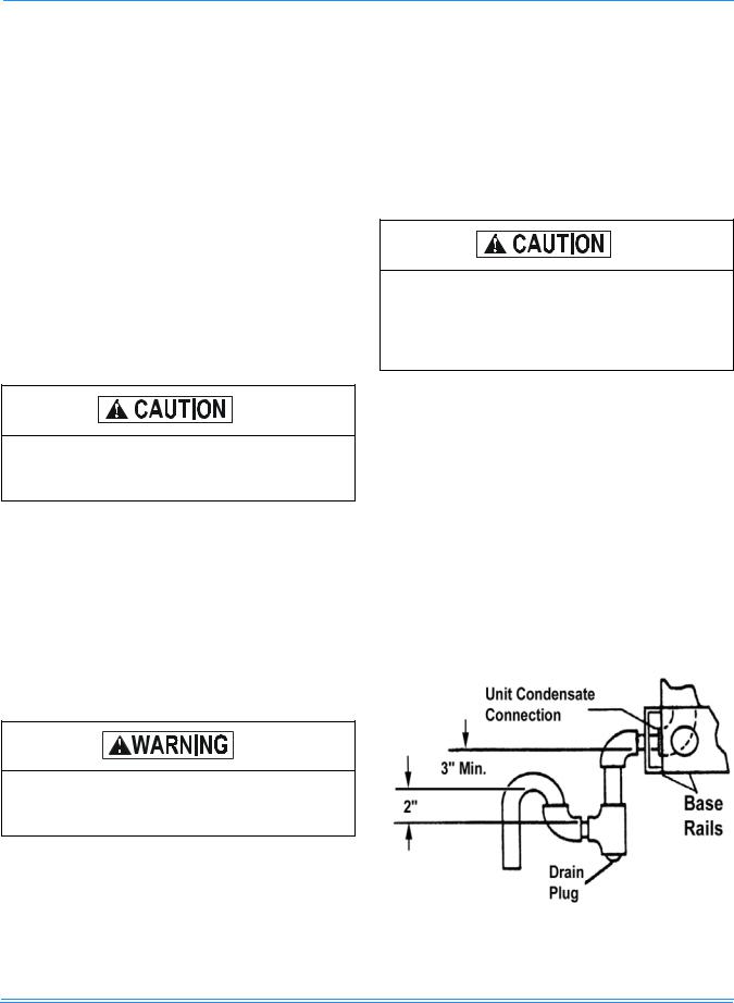
Plumbing must conform to local codes. Use a sealing compound on male pipe threads. Install a condensate drain line from the 3/4" NPT female connection on the unit to an open drain.
NOTE: The condensate drain operates in a negative pressure in the cabinet. The condensate drain line MUST be trapped to provide proper drainage. See Figure 1.
FIGURE 1 - RECOMMENDED DRAIN PIPING
Johnson Controls Unitary Products |
7 |
364985-XIM-B-0508
COMPRESSORS
Units are shipped with compressor mountings factoryadjusted and ready for operation.
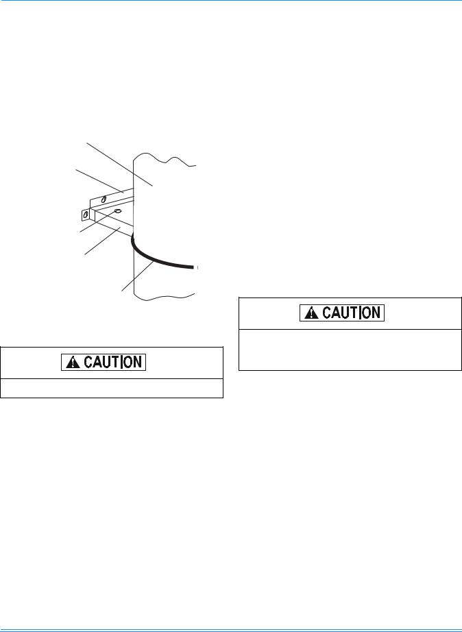
Units with scroll compressors have a shipping bracket which must be removed after the unit is set in place. See Figure 2.
COMPRESSOR
MOUNTING
BRACKET BASE
REMOVE THESE
SCREWS (2)
MOUNTING BRACKET TOP (REMOVE)
WIRE TIE (CUT AND REMOVE)
FILTERS
One-inch or two-inch filters can be supplied with each unit. Filters must always be installed ahead of the evaporator coil and must be kept clean or replaced with same size and type. Dirty filters will reduce the capacity of the unit and will result in frosted coils or safety shutdown. Minimum filter area and required sizes are shown in Physical Data Table 7.
SERVICE ACCESS
The following removable panels provide access to all serviceable components:
•Compressor compartment
•Electric Heat compartment
•Blower compartment
•Main control box
•Filter compartment
Refer to the Dimensions and Clearances shown in Figures 7 and 11 for location of these access panels.
FIGURE 2 - COMPRESSOR RESTRAINING BRACKET
Do not loosen compressor mounting bolts.
Make sure that all screws and panel latches are replaced and properly positioned on the unit to maintain an airtight seal.
8 |
Johnson Controls Unitary Products |

364985-XIM-B-0508
TYPICAL POWER WIRING
REFER TO THE ELECTRICAL DATA
TABLES TO SIZE THE DISCONNECT
SWITCH, OVERCURRENT PROTEC-
TION AND WIRING.
TYPICAL CONTROL WIRING
COOLING / HEATING (24 VOLT THERMOSTAT)
THERMOSTAT1
TERMINALS
|
RH |
UNIT TERMINAL |
|
ADD |
STRIP TB1 |
|
|
|
|
|
|
JUMPER |
RC |
R |
|
|
Y |
Y1 |
24 VOLT |
|
|
Y2 |
TRANSFORMER |
|
|
|
WW1
W2
GG
C
124 VOLT THERMOSTAT 2ET07701024. TO CONTROL THE ECONOMIZER ON THE SECOND STAGE COOLING OR TO HAVE AN ELECTRIC HEAT ACCESSORY WITH TWO STAGES OF HEAT, USE THERMOSTAT 2TH0471024.
COOLING / HEATING (ELECTRONIC THERMOSTAT) |
COOLING / HEATING (ELECTRONIC THERMOSTAT) |
MULTI STAGE |
SINGLE STAGE |
THERMOSTAT1 |
|
|
|
|
THERMOSTAT1 |
|
|
TERMINALS |
|
UNIT TERMINAL |
|
|
UNIT TERMINAL |
||
|
|
|
TERMINALS |
||||
|
RC |
|
STRIP TB1 |
24 VOLT |
|
||
ADD |
|
|
RH |
STRIP TB1 |
|||
RH |
|
R |
TRANSFORMER |
|
|
||
JUMPER |
|
|
RC |
R |
|||
Y1 |
|
Y1 |
|
ADD |
|||
|
2 |
|
Y |
Y1 |
|||
|
Y2 |
Y2 |
|
JUMPER |
|||
|
|
W |
W1 |
||||
|
W1 |
|
W1 |
|
|
||
4 |
|
|
|
G |
G |
||
W2 |
3 |
W2 |
|
|
|||
|
|
|
C |
||||
|
G |
|
G |
|
|
|
|
|
|
|
|
|
24 VOLT |
||
|
B |
|
C |
|
|
|
|
|
|
|
|
|
TRANSFORMER |
||
|
|
|
|
|
|
|
|
|
LED 1 |
|
X |
|
|
LED 2 |
NOT |
OCC |
1ELECTRONIC PROGRAMMABLE THERMOSTAT 2ET07701024 (INCLUDES SUBBASE). |
|
|
USED 4 |
|
|
|
COM |
|
||
|
|
TO CONTROL THE ECONOMIZER ON SECOND STAGE COOLING, USE THERMOSTAT |
||
ADD |
A1 |
|
|
2TH04700224. |
JUMPER |
A2 |
|
|
|
T TO REMOTE SENSOR
T 2TH040702224 IF USED
1 ELECTRONIC PROGRAMMABLE THERMOSTAT 2ET04700224 (INCLUDES SUBBASE). 2 SECOND STAGE COOLING IS NOT REQUIRED ON UNITS LESS ECONOMIZER.
3SECOND STAGE HEATING IS ONLY REQUIRED ON UNITS WITH A TWO STAGE ELECTRIC HEATER OR 2 STAGE GAS HEAT.
4REMOVE JUMPER J2 FROM TERMINALS 4 AND 9 ON JUMPER PLUG CONNECTOR P6 ON UNITS WITH ECONOMIZER. TERMINALS A1 AND A2 PROVIDE A RELAY OUT-PUT TO CLOSE THE OUTDOOR ECONOMIZER DAMPERS WHEN THE THERMOSTAT SWITCHES TO THE SET-BACK POSITION.
FIGURE 3 - TYPICAL FIELD POWER & CONTROL WIRING
Johnson Controls Unitary Products |
9 |

364985-XIM-B-0508
THERMOSTAT
The room thermostat should be located on an inside wall approximately 56 inches above the floor where it will not be subject to drafts, sun exposure or heat from electrical fixtures or appliances. Follow the manufacturer's instructions enclosed with the thermostat for general installation procedure. A minimum of seven color-coded insulated wires (#18 AWG) should be used to connect the thermostat to the unit.
POWER AND CONTROL WIRING
Field wiring to the unit must conform to provisions of the National Electrical Code, ANSI / NFPA No. 70 (in U.S.A.), current Canadian Electrical Code C22.1 (in Canada) and/or local ordinances. The unit must be electrically grounded in accordance with NEC and CEC (as specified above) and/or local codes. Voltage tolerances, which must be maintained at the compressor terminals, during starting and running conditions, are indicated on the unit Rating Plate and the Unit Application Data table.
The internal wiring harness furnished with this unit is an integral part of a CSA design certified unit. Field alteration to comply with electrical codes should not be required.
A fused disconnect switch should be field provided for the unit. The switch must be separate from all other circuits. Wire entry at knockout openings require conduit fittings to comply with NEC (in U.S.A.), CEC (in Canada) and/or local codes. If any of the wire supplied with the unit must be replaced, replacement wire must be of the type shown on the wiring diagram and the same minimum gauge as the replaced wire.
Use copper conductors properly sized to carry the load. Each unit must be wired with a separate branch circuit fed directly from the meter panel and properly fused.
When connecting electrical power and control wiring to the unit, waterproof type connectors MUST BE USED so that water or moisture cannot be drawn into the unit during normal operation. The above waterproofing conditions will also apply when installing a field-supplied disconnect switch.
Refer to the Typical Field Wiring Figure 3 and to the appropriate unit wiring diagram for control circuit and power wiring information.
TABLE 2: CONTROL WIRE SIZES
Wire Size |
Maximum Length1 |
18 AWG |
150 Feet |
|
|
1. From the unit to the thermostat and back to the unit.
OPTIONS/ACCESSORIES
ELECTRIC HEAT
The factoryor field-installed heaters are wired for single point power supply. Power supply need only be brought into the single point terminal block and thermostat wiring to the low voltage terminal strip located in the upper portion of the unit control box.
These CSA approved heaters are located within the central compartment of the unit with the heater elements extending into the supply air chamber. Refer to Figure 7 for access panel location.
Fuses are supplied, where required, by the factory. Some KW sizes require fuses and others do not. Refer to Table 3 for minimum CFM limitations and to Tables 9 through 14 for electrical data.
10 |
Johnson Controls Unitary Products |
364985-XIM-B-0508
TABLE 3: ELECTRIC HEATER CFM LIMITATIONS
UNIT MODEL SIZE |
|
|
|
MINIMUM SUPPLY AIR CFM |
|
|
|||
VOLTAGE |
|
|
HEATER SIZE NOMINAL KW |
|
|
||||
NOMINAL TONS |
|
|
|
|
|||||
|
5 |
7 |
|
10 |
15 |
|
20 |
30 |
|
|
|
|
|
||||||
|
208/230-1-60 |
900 |
900 |
|
900 |
900 |
|
900 |
- |
036 |
208/230-3-60 |
900 |
900 |
|
900 |
900 |
|
900 |
- |
(3) |
460-3-60 |
- |
900 |
|
900 |
900 |
|
900 |
- |
|
600-3-60 |
- |
- |
|
900 |
900 |
|
900 |
- |
|
208/230-1-60 |
1200 |
1200 |
|
1200 |
1200 |
|
1200 |
- |
048 |
208/230-3-60 |
1200 |
1200 |
|
1200 |
1200 |
|
1200 |
- |
(4) |
460-3-60 |
- |
1200 |
|
1200 |
1200 |
|
1200 |
- |
|
600-3-60 |
- |
- |
|
1200 |
1200 |
|
1200 |
- |
|
208/230-1-60 |
1500 |
1500 |
|
1500 |
1500 |
|
1500 |
1500 |
060 |
208/230-3-60 |
1500 |
1500 |
|
1500 |
1500 |
|
1500 |
1500 |
(5) |
460-3-60 |
- |
1500 |
|
1500 |
1500 |
|
1500 |
1500 |
|
600-3-60 |
- |
- |
|
1500 |
1500 |
|
1500 |
1500 |
ECONOMIZER/MOTORIZED DAMPER AND RAIN HOOD
The instruction for the optional economizer/motorized damper and rain hood can be found in form 035- 07364-000. Use these instructions when field assembling an economizer rain hood onto a unit. The outdoor and return air dampers, the damper actuator, the damper linkage, the outdoor and return air divider baffles, and all the control sensors are factory mounted as part of the “Factory installed” economizer/motorized damper options.
POWER EXHAUST/BAROMETRIC RELIEF DAMPER AND RAIN HOOD
The instructions for the power exhaust/barometric relief damper and rain hood can be found in form 530.18N1.10V.
All of the components, including the dampers, hardware, and mounting instructions are shipped in a single package external from the unit and must be field assembled and installed.
Power exhaust is only available as a field installed accessory.
ECONOMIZER AND POWER EXHAUST DAMPER SET POINT ADJUSTMENTS AND INFORMATION
Remove the economizer access panel from the unit. Loosen but do not remove the two panel latches. Locate the economizer control module, where the following adjustments will be made.
Extreme care must be exercised in turning all setpoint, maximum, and minimum damper positioning adjustment screws to prevent twisting them off.
Check that the damper blades move smoothly without binding; carefully turn the Minimum Position Adjusting screw (found on the damper control module) fully clockwise and then set the thermostat indoor fan switch to the on position and then off, or energize and deenergize terminals “R” to “G”.
Johnson Controls Unitary Products |
11 |

364985-XIM-B-0508
MINIMUM POSITION ADJUSTMENT
With thermostat set to indoor fan on position, or terminals “R” to “G” energized, turn the Minimum Position Adjusting screw (located on the damper control module) counterclockwise until the desired minimum damper position has been attained.
ENTHALPY SET POINT ADJUSTMENT
The enthalpy setpoint may now be set by selecting the desired setpoint shown in the Enthalpy Setpoint Adjustment Figure 4. Adjust as follows:
•For a single enthalpy operation carefully turn the setpoint adjusting screw (found on the damper control module) to the “A”, “B”, “C” or “D” setting corresponding to the lettered curve of the Enthalpy Setpoint Adjustment Figure 4.
•For a dual enthalpy operation, carefully turn the setpoint adjusting screw fully clockwise past the “D” setting.
POWER EXHAUST DAMPER SETPOINT (WITH OR WITHOUT POWER EXHAUST)
•With no power exhaust option, adjust the Exhaust Air Adjustment Screw fully clockwise.
•With power exhaust option, each building pressurization requirement will be different. The point at which the power exhaust comes on is determined by the economizer damper position (Percent Open). The Exhaust Air Adjustment Screw should be set at the Percent Open of the economizer damper at which the power exhaust is needed. It can be set from 0 to 100% damper open.
INDOOR AIR QUALITY
Indoor air quality (indoor sensor input): Terminal AQ accepts a +2 to +10 Vdc signal with respect to the (AQ1) terminal. When the signal is below it's setpoint, the actuator is allowed to modulate normally in accordance with the enthalpy and mixed air sensor inputs. When the AQ signal exceeds it's setpoint setting and there is no call for free cooling, the actuator is proportionately modulated from the 2 to 10 Vdc signal, with 2 Vdc corresponding to full closed and 10 Vdc corresponding to full open. When there is no call for free cooling, the damper position is limited by the IAQ Max damper position setting. When the signal exceeds it's setpoint (Demand Control Ventilation Setpoint) setting and there is a call for free cooling, the actuator modulates from the minimum position to the full open position based on the highest call from either the mixed air sensor input or the AQ voltage input.
•Optional CO2 Space Sensor Kit Part # 2AQ04700324
•Optional CO2 Unit Sensor Kit Part # 2AQ04700424
Replace the economizer access panel.
12 |
Johnson Controls Unitary Products |
Loading...