


TG9SMP
INSTALLATION MANUAL
RESIDENTIAL GAS FURNACE MODELS
TG9S*MP, GG9S*MP
(95.5% AFUE Single Stage Multi-position)
LIST OF SECTIONS
SAFETY . . . . . . . . . . . . . . . . . . . . . . . . . . . . . . . . . . . . . . . . . . . . . . . 1
DUCTWORK . . . . . . . . . . . . . . . . . . . . . . . . . . . . . . . . . . . . . . . . . . . 5
FILTERS . . . . . . . . . . . . . . . . . . . . . . . . . . . . . . . . . . . . . . . . . . . . . 10
GAS PIPING . . . . . . . . . . . . . . . . . . . . . . . . . . . . . . . . . . . . . . . . . . 12
ELECTRICAL POWER . . . . . . . . . . . . . . . . . . . . . . . . . . . . . . . . . . 13
TWINNING AND STAGING . . . . . . . . . . . . . . . . . . . . . . . . . . . . . . . 17
CONDENSATE PIPING AND FURNACE
VENTING CONFIGURATION . . . . . . . . . . . . . . . . . . . . . . . . . . . . . 19
LIST OF FIGURES
Duct Attachment . . . . . . . . . . . . . . . . . . . . . . . . . . . . . . . . . . . . . . . . . 5
Vertical Applications . . . . . . . . . . . . . . . . . . . . . . . . . . . . . . . . . . . . . . 5
Coil Flange . . . . . . . . . . . . . . . . . . . . . . . . . . . . . . . . . . . . . . . . . . . . . 6
Horizontal Right Application . . . . . . . . . . . . . . . . . . . . . . . . . . . . . . . . 6
Horizontal Left Application . . . . . . . . . . . . . . . . . . . . . . . . . . . . . . . . . 6
PC Series Upflow Coil Installation . . . . . . . . . . . . . . . . . . . . . . . . . . . 6
Horizontal Left or Right application (Right Shown) . . . . . . . . . . . . . . 6
Combustible Floor Base Accessory . . . . . . . . . . . . . . . . . . . . . . . . . . 7
Horizontal Application . . . . . . . . . . . . . . . . . . . . . . . . . . . . . . . . . . . . 7
Typical Attic Installation . . . . . . . . . . . . . . . . . . . . . . . . . . . . . . . . . . . 7
Typical Suspended Furnace / Crawl Space Installation . . . . . . . . . . . 7
Dimensions . . . . . . . . . . . . . . . . . . . . . . . . . . . . . . . . . . . . . . . . . . . . 8
Side Return Cutout Markings . . . . . . . . . . . . . . . . . . . . . . . . . . . . . . . 9
Gas Valve . . . . . . . . . . . . . . . . . . . . . . . . . . . . . . . . . . . . . . . . . . . . . . 9
Upflow/Downflow Gas Piping . . . . . . . . . . . . . . . . . . . . . . . . . . . . . . . 9
Horizontal Gas Piping . . . . . . . . . . . . . . . . . . . . . . . . . . . . . . . . . . . . 9
Electrical Wiring . . . . . . . . . . . . . . . . . . . . . . . . . . . . . . . . . . . . . . . . 11
Thermostat Chart - Single Stage AC with
Single Stage PSC Furnaces . . . . . . . . . . . . . . . . . . . . . . . . . . . . . . 12
Thermostat Chart - Single Stage HP with
Single Stage PSC Furnaces . . . . . . . . . . . . . . . . . . . . . . . . . . . . . . 13
Typical Twinned Furnace Application . . . . . . . . . . . . . . . . . . . . . . . 14
EFFICIENCY
RATING
CERTIFIED
ISO 9001
Certified Quality
Management System
COMBUSTION AIR and VENT SYSTEM . . . . . . . . . . . . . . . . . . . .24
START-UP AND ADJUSTMENTS . . . . . . . . . . . . . . . . . . . . . . . . . .31
SAFETY CONTROLS . . . . . . . . . . . . . . . . . . . . . . . . . . . . . . . . . . .34
REPLACEMENT PARTS LIST . . . . . . . . . . . . . . . . . . . . . . . . . . . .39
REPLACEMENT PART CONTACT INFORMATION . . . . . . . . . . . . 39
WIRING DIAGRAM . . . . . . . . . . . . . . . . . . . . . . . . . . . . . . . . . . . . .40
Single Stage Twinning Wiring Diagram . . . . . . . . . . . . . . . . . . . . . .15
Two-Stage Twinning Wiring Diagram . . . . . . . . . . . . . . . . . . . . . . . .15
Upflow Configuration . . . . . . . . . . . . . . . . . . . . . . . . . . . . . . . . . . . .17
Downflow Configuration . . . . . . . . . . . . . . . . . . . . . . . . . . . . . . . . . .18
Horizontal Left Configuration . . . . . . . . . . . . . . . . . . . . . . . . . . . . . .19
Horizontal Right Configuration . . . . . . . . . . . . . . . . . . . . . . . . . . . . .20
Dimensions . . . . . . . . . . . . . . . . . . . . . . . . . . . . . . . . . . . . . . . . . . . .21
Home Layout . . . . . . . . . . . . . . . . . . . . . . . . . . . . . . . . . . . . . . . . . .23
Termination Configuration - 1 Pipe . . . . . . . . . . . . . . . . . . . . . . . . . .24
Termination Configuration - 2 Pipe . . . . . . . . . . . . . . . . . . . . . . . . . .24
Termination Configuration - 2 Pipe Basement . . . . . . . . . . . . . . . . .24
Double Horizontal Combustion Air Intake and Vent Termination . . .24
Double Vertical Combustion Air Intake and Vent Termination . . . . . 24
Direct Vent Air Intake Connection and Vent Connection . . . . . . . . .25
Combustion Airflow Path Through The Furnace Casing . . . . . . . . .25
Outside and Ambient Combustion Air . . . . . . . . . . . . . . . . . . . . . . . .26
Attic and Crawl Space Combustion Air Termination . . . . . . . . . . . . .27
Gas Valve . . . . . . . . . . . . . . . . . . . . . . . . . . . . . . . . . . . . . . . . . . . . .30
Reading Gas Pressure . . . . . . . . . . . . . . . . . . . . . . . . . . . . . . . . . . .30
Furnace Control Board . . . . . . . . . . . . . . . . . . . . . . . . . . . . . . . . . . .31
Furnace Control Event Schedule . . . . . . . . . . . . . . . . . . . . . . . . . . .33
Wiring Diagram . . . . . . . . . . . . . . . . . . . . . . . . . . . . . . . . . . . . . . . . .35
LIST OF TABLES
Unit Clearances to Combustibles . . . . . . . . . . . . . . . . . . . . . . . . . . . . 4
Coil Projection Dimensions - PC Series Coils . . . . . . . . . . . . . . . . . . 6
Cabinet and Duct Dimensions . . . . . . . . . . . . . . . . . . . . . . . . . . . . . . 8
Recommended Filter Sizes (High Velocity 600 FPM) . . . . . . . . . . . . 8
Nominal Manifold Pressure - High Fire . . . . . . . . . . . . . . . . . . . . . . 10
Ratings & Physical / Electrical Data . . . . . . . . . . . . . . . . . . . . . . . . . 11
Maximum Equivalent Pipe Length . . . . . . . . . . . . . . . . . . . . . . . . . . 21
Elbow Dimensions . . . . . . . . . . . . . . . . . . . . . . . . . . . . . . . . . . . . . . 21
Equivalent Length of Fittings . . . . . . . . . . . . . . . . . . . . . . . . . . . . . . 22
These high efficiency, compact units employ induced combustion, reliable hot surface ignition and high heat transfer aluminized tubular heat
exchangers. The units are factory shipped for installation in upflow or
horizontal applications and may be converted for downflow applications.
These furnaces are designed for residential installation in a basement,
closet, alcove, attic, recreation room or garage and are also ideal fo r
commercial applications. All units are factory assembled, wired and
tested to assure safe dependable and economical installation and operation.
These units are Category IV listed and may not be common vented with
another gas appliance as allowed by the National Fuel Gas Code.
SECTION I: SAFETY
This is a safety alert symbol. When you see this symbol on
labels or in manuals, be alert to the potential for personal
injury.
Understand and pay particular attention to the signal words DANGER,
WARNING, or CAUTION.
Combustion Air Intake and Vent Connection Size at Furnace (All Models) . . . . . . . . . . . . . . . . . . . . . . . . . . . . . . . . . . . . . . . . . . . . . . . . . . 22
Estimated Free Area . . . . . . . . . . . . . . . . . . . . . . . . . . . . . . . . . . . . .25
Unconfined Space Minimum Area in Square Inch . . . . . . . . . . . . . . 26
Free Area . . . . . . . . . . . . . . . . . . . . . . . . . . . . . . . . . . . . . . . . . . . . .26
Gas Rate (CU FT/HR) at Full Input . . . . . . . . . . . . . . . . . . . . . . . . . . 29
Inlet Gas Pressure Range . . . . . . . . . . . . . . . . . . . . . . . . . . . . . . . .30
Nominal Manifold Pressure . . . . . . . . . . . . . . . . . . . . . . . . . . . . . . . .30
DANGER indicates an imminently hazardous situation, which, if not
avoided, will result in death or serious injury
WARNING indicates a potentially hazardous situation, which, if not
avoided, could result in death or serious injury
CAUTION indicates a potentially hazardous situation, which, if not
avoided may result in minor or moderate injury.
alert against unsafe practices and hazards involving only property damage.
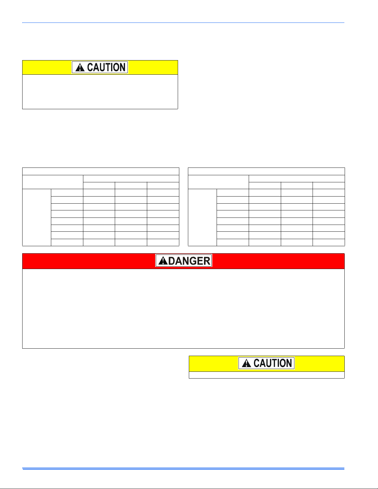
Improper installation may create a condition where the operation of
the product could cause personal injury or property damage.
Improper installation, adjustment, alteration, service or maintenance can cause injury or property damage. Failure to carefully
read and follow all instructions in this manual can result in furnace malfunction, death, personal injury and/or property damage. Only a qualifie d contractor, installer or service agency should
install this product.
.
.
It is also used to
364861-UIM-B-0708
364861-UIM-B-0708
SPECIFIC SAFETY RULES AND PRECAUTIONS
1. Only Natural gas or Propane (LP) gas are approved for use with
this furnace.
2. Install this furnace only in a location and position as specified in
these instructions.
3. A gas-fired furnace for installation in a residential garage must be
installed as specified in these instructions.
4. Provide adequate combustion and ventilation air to the furnace
space as specified in these instructions.
5. Combustion products must be discharged outdoors. Connect this
furnace to an approved vent system only, as specified in SECTION VIII, "COMBUSTION AIR and VENT SYSTEM" of these
instructions.
6. Test for gas leaks as specified in these instructions.
FIRE OR EXPLOSION HAZARD
Failure to follow the safety warnings exactly could result in serious
injury, death or property damage.
Never test for gas leaks with an open flame. Use a commercially
available soap solution made specifically for detection of leaks to
check all connections. A fire or explosion may result causing property damage, personal injury or loss of life.
7. Always install the furnace to operate within the furnace’s intended
temperature rise range. Only connect the furnace to a duct system
which has an external static pressure within the allowable range,
as specified on the furnace rating plate.
8. When a furnace is installed so that supply ducts carry air circulated
by the furnace to areas outside the space containing the furnace,
the return air shall also be handled by duct(s) sealed to the furnace casing and terminating outside the space containing the furnace.
9. It is permitted to use the furnace for heating of buildings or structures under construction where the application and use must comply with all manufacturer’s installation instructions including:
• Proper vent installation;
• Furnace operating under thermostatic control;
• Return air duct sealed to the furnace;
• Air filters in place;
• Set furnace input rate and temperature rise per rating plate
marking;
• Means for providing outdoor air required for combustion;
• Return air temperature maintained between 55ºF (13ºC) and
80ºF (27ºC);
• The air filter must be replaced upon substantial completion of
the construction process;
• Clean furnace, duct work and components upon substantial
completion of the construction process, and verify furnaceoperating conditions including ignition, input rate, temperature
rise and venting, according to the manufacturer’s instructions.
10. When installed in a Non-HUD-Approved Modular Home or building
constructed on-site, combustion air shall not be supplied from
occupied spaces.
11. The size of the unit should be based on an acceptable heat loss
calculation for the structure. ACCA, Manual J or other approved
methods may be used.
SAFETY REQUIREMENTS
• Refer to the unit rating plate for the furnace model number, and
then see the dimensions page of this instruction for return air plenum dimensions in Figure 12, "Dimensions". The plenum must be
installed according to the instructions.
• Provide clearances from combustible materials as listed under
Clearances to Combustibles.
• Provide clearances for servicing ensuring that service access is
allowed for both the burners and blower.
• These models ARE NOT
into a HUD Approved Modular Home
(Mobile) Home.
• This furnace is not approved for installation in trailers or recreational vehicles.
• Furnaces for installation on combustible flooring shall not be
installed directly on carpeting, tile or other combustible material
other than wood flooring.
• Check the rating plate and power supply to be sure that the electrical characteristics match. All models use nominal 115 VAC, 1
Phase, 60-Hertz power supply. DO NOT CONNECT THIS APPLIANCE TO A 50 HZ POWER SUPPLY OR A VOLTAGE ABOVE
130 VOLTS.
• Furnace shall be installed so the electrical components are protected from water.
• Installing and servicing heating equipment can be hazardous due
to the electrical components and the gas fired components. Only
trained and qualified personnel should install, repair, or service
gas heating equipment. Untrained service personnel can perform
basic maintenance functions such as cleaning and replacing the
air filters. When working on heating equipment, observe precautions in the manuals and on the labels attached to the unit and
other safety precautions that may apply.
CSA listed or approved for installation
or a Manufactured
COMBUSTION AIR QUALITY
(LIST OF CONTAMINANTS)
The furnace requires OUTDOOR AIR for combustion when the furnace
is located in any of the following environments.
• Restricted Environments
• Commercial buildings
• Buildings with indoor pools
• Furnaces installed in laundry rooms
• Furnaces installed in hobby or craft rooms
• Furnaces installed near chemical storage areas
• Chemical exposure
The furnace requires OUTDOOR AIR for combustion when the furnace
is located in an area where the furnace is being exposed to the following substances and / or chemicals.
• Permanent wave solutions
• Chlorinated waxes and cleaners
• Chlorine based swimming pool chemicals
• Water softening chemicals
• De-icing salts or chemicals
• Carbon tetrachloride
• Halogen type refrigerants
• Cleaning solvents (such as perchloroethylene)
• Printing inks, paint removers, varnishes, etc.
• Hydrochloric acid
• Cements and glues
• Antistatic fabric softeners for clothes dryers
• Masonry acid washing materials
When outdoor air is used for combustion, the combustion air intake duct
system termination must be located external to the building and in an
area where there will be no exposure to the substances listed above.
This product must be installed in strict compliance with the installation instructions and any applicable local, state, and national codes
including, but not limited to building, electrical, and mechanical
codes.
2 Johnson Controls Unitary Products
The furnace area must not be used as a broom closet or for any
other storage purposes, as a fire hazard may be created. Never
store items such as the following on, near or in contact with the furnace.
1. Spray or aerosol cans, rags, brooms, dust mops, vacuum
cleaners or other cleaning tools.
2. Soap powders, bleaches, waxes or other cleaning compounds; plastic items or containers; gasoline, kerosene, cigarette lighter fluid, dry cleaning fluids or other volatile fluid.
3. Paint thinners and other painting compounds.
4. Paper bags, boxes or other paper products
Never operate the furnace with the blower door removed. To
do so could result in serious personal injury and/or equipment
damage.
CODES AND STANDARDS
Follow all national, local codes and standards in addition to this installation manual. The installation must comply with regulations of the serving gas supplier, local building, heating, plumbing, and other codes. In
absence of local codes, the installation must comply with the national
codes listed below and all authorities having jurisdiction.
In the United States and Canada, follow all codes and standards for the
following, using the latest edition available:
STEP 1 -Safety
• US: National Fuel Gas Code (NFGC) NFPA 54/ANSI Z223.1 and
the Installation Standards, Warm Air Heating and Air Conditioning
Systems ANSI/NFPA 90B
• CANADA: CAN/CGA-B149.1 National Standard of Canada. Natural Gas and Propane Installation Codes (NSCNGPIC)
STEP 2 -General Installation
• US: Current edition of the NFGC and NFPA 90B. For copies, contact the
National Fire Protection Association Inc.
Batterymarch Park
Quincy, MA 02269
or for only the NFGC, contact the
American Gas Association,
400 N. Capital, N.W.
Washington DC 20001
or www.NFPA.org
• CANADA: NSCNGPIC. For a copy contact:
Standard Sales, CSA International
178 Rexdale Boulevard
Etobicoke, (Toronto) Ontario Canada M9W 1RS
STEP 3 -Combustion and Ventilation Air
• US: Section 5.3 of the NFGC, air for Combustion and Ventilation
• CANADA: Part 7 of NSCNGPIC, Venting Systems and Air Supply
for Appliances
STEP 4 -Duct Systems
• US and CANADA: Air Conditioning Contractors Association
(ACCA) Manual D, Sheet Metal and Air Conditioning Contractors
Association National Association (SMACNA), or American Society of Heating, Refrigeration, and Air Conditioning Engineers
(ASHRAE) 1997 Fundamentals Handbook Chapter 32.
STEP 5 -Acoustical Lining and Fibrous Glass Duct
• US and CANADA: Current edition of SMACNA and NFPA 90B as
tested by UL Standard 181 for Class I Rigid Air Ducts
STEP 6 -Gas Piping and Gas Pipe Pressure Testing
• US: NFGC; chapters 2, 3, 4, & 9 and National Plumbing Codes
• CANADA: NSCNGPIC Part 5
STEP 7 -Electrical Connections
• US: National Electrical Code (NEC) ANSI/NFPA 70
• CANADA: Canadian Electrical Code CSA C22.1
364861-UIM-B-0708
These instructions cover minimum requirements and conform to existing national standards and safety codes. In some instances these
instructions exceed certain local codes and ordinances, especially
those who have not kept up with changing residential and non-HUD
modular home construction practices. These instructions are required
as a minimum for a safe installation.
FOR FURNACES INSTALLED IN THE COMMONWEALTH OF MASSACHUSETTS ONLY
For all side wall horizontally vented gas fueled equipment installed in
every dwelling, building or structure used in whole or in part for residential purposes, including those owned or operated by the Commonwealth and where the side wall exhaust vent termination is less
than seven (7) feet above finished grade in the area of the venting,
including but not limited to decks and porches, the following requirements shall be satisfied:
1. INSTALLATION OF CARBON MONOXIDE DETECTORS. At
the time of installation of the side wall horizontal vented gas
fueled equipment, the installing plumber or gasfitter shall
observe that a hard wired carbon monoxide detector with an
alarm and battery back-up is installed on the floor level where
the gas equipment is to be installed. In addition, the installing
plumber or gasfitter shall observe that a battery operated or
hard wired carbon monoxide detector with an alarm is installed
on each additional level of the dwelling, building or structure
served by the side wall horizontal vented gas fueled equipment.
It shall be the responsibility of the property owner to secure the
services of qualified licensed professionals for the installation of
hard wired carbon monoxide detectors
a. In the event that the side wall horizontally vented gas
fueled equipment is installed in a crawl space or an attic,
the hard wired carbon monoxide detector with alarm and
battery back-up may be installed on the next adjacent floor
level.
b. In the event that the requirements of this subdivision can
not be met at the time of completion of installation, the
owner shall have a period of thirty (30) days to comply with
the above requirements; provided, however, that during
said thirty (30) day period, a battery operated carbon monoxide detector with an alarm shall be installed.
2. APPROVED CARBON MONOXIDE DETECTORS. Each carbon monoxide detector as required in accordance with the
above provisions shall comply with NFPA 720 and be ANSI/UL
2034 listed and IAS certified.
3. SIGNAGE. A metal or plastic identification plate shall be permanently mounted to the exterior of the building at a minimum
height of eight (8) feet above grade directly in line with the
exhaust vent terminal for the horizontally vented gas fueled
heating appliance or equipment. The sign shall read, in print
size no less than one-half (1/2) inch in size, "GAS VENT
DIRECTLY BELOW. KEEP CLEAR OF ALL OBSTRUCTIONS".
4. INSPECTION. The state or lo cal gas inspector of the side wall
horizontally vented gas fueled equipment shall not approve the
installation unless, upon inspection, the inspector observes carbon monoxide detectors and signage installed in accordance
with the provisions of 248 CMR 5.08(2)(a)1 through 4.
INSPECTION
As soon as a unit is received, it should be inspected for possib le damage during transit. If damage is evident, the extent of the damage
should be noted on the carrier’s freight bill. A separate request for
inspection by the carrier’s agent should be made in writing. Also, before
installation, the unit should be checked for screws or bolts which may
have loosened in transit. There are no shipping or spacer brackets
which need to be removed from the interior of this unit.
Johnson Controls Unitary Products 3

364861-UIM-B-0708
FURNACE LOCATION AND CLEARANCES
The furnace shall be located using the following guidelines:
1. Where a minimum amount of air intake/vent piping and elbows will
be required.
2. As centralized with the air distribution as possible.
3. Where adequate combustion air will be available (particularly
when the appliance is not using outdoor combustion air).
4. Where it will not interfere with proper air circulation in the confined
space.
5. Where the outdoor vent terminal will not be blocked or restricted.
Refer to “VENT CLEARANCES” located in SECTION VII of these
instructions. These minimum clearances must be maintained in
the installation.
6. Where the unit will be installed in a level position with no more than
1/4” (6.4 mm) slope side-to-side and front-to-back to provide
proper condensate drainage.
Installation in freezing temperatures:
1. Furnace shall be installed in an area where ventilation facilities
provide for safe limits of ambient temperature under normal operating conditions. Ambient temperatures must not fall below 32°F
(0°C) unless the condensate system is protected from freezing.
Improper installation in an ambient below 32ºF (0.0° C) could create
a hazard, resulting in damage, injury or death.
2. Do not allow return air temperature to be below 55º F (13° C) for
extended periods. To do so may cause condensation to occur in
the main heat exchanger, leading to premature heat exchanger
failure.
3. If this furnace is installed in an unconditioned space and an
extended power failure occurs, there will be potential damage to
the internal components. Following a power failure situation, do
not operate the unit until inspection and repairs are performed.
4. Special precautions MUST be made if installing furnace in an area
which may drop below freezing. This can cause improper operation or damage to the equipment. If the furnace is installed in an
area that has the potential of freezing, the drain line must be protected. Use a 3 to 6 watt per foot at 115 vac, 40º F (4.4° C) selfregulating, shielded and waterproof heat tape. Wrap the drain line
outside of the furnace with the heat tape and secure with ties. Follow the heat tape manufacturer's recommendations.
Use only Propylene Glycol (RV anti-freeze) to winterize the furnace.
Refer to the manufacturer’s specification to ensure that it is compatible with plastics and other components of the furnace. DO NOT
use Ethylene Glycol anti-freeze in the furnace.
Clearances for access/service:
Ample clearances should be provided to permit easy access to the unit.
The following minimum clearances are recommended:
1. Twenty-four (24) inches (61 cm) between the front of the furnace
and an adjacent wall or another appliance, when access is
required for servicing and cleaning.
2. Eighteen (18) inches (46 cm) at the side where access is required
for passage to the front when servicing or for inspection or replacement of flue/vent connections.
In all cases, accessibility clearances shall take precedence over clearances for combustible materials where accessibility clearances are
greater.
Installation in a residential garage:
A gas-fired furnace for installation in a residential garage must be
installed so the burner(s) and the ignition source are located not less
than 18 inches (46 cm) above the floor, and the furnace must be located
or protected to avoid physical damage by vehicles.
Table 1:
Unit Clearances to Combustibles
Application
Top 1" 0" 0"
Vent 0" 0" 0"
Rear 0" 0" 0"
Side 0" 0" 1"
Front* 0" 0" 0"
Floor Combustible
Closet Yes Yes Yes
Line Contact No No Yes
1. For combustible floors only when used with special sub-base.
* - 24" clearance in front and 18" on side recommended for service access.
All furnaces approved for alcove and attic installation.
Upflow Downflow Horizontal
1
Combustible
Combustible
SECTION II: DUCTWORK
DUCTWORK GENERAL INFORMATION
The duct system’s design and installation must:
1. Handle an air volume appropriate for the served space and within
the operating parameters of the furnace specifications.
2. Be installed in accordance of National Fire Protection Association
as outlined in NFPA standard 90B (latest editions) or applicable
national, provincial, state, and local fire and safety codes.
3. Create a closed duct system. For residential and Non-HUD Modular Home installations, when a furnace is installed so that the supply ducts carry air circulated by the furnace to areas outside the
space containing the furnace, the return air shall also be handled
by a duct(s) sealed to the furnace casing and terminating outside
the space containing the furnace.
4. Complete a path for heated or cooled air to circulate through the
air conditioning and heating equipment and to and from the conditioned space.
The cooling coil must be installed in the supply air duct, downstream of the furnace. Cooled air may not be passed over the heat
exchanger.
When the furnace is used with a cooling coil, the coil must be installed
parallel with, or in the supply air side of the furnace to avoid condensation in the primary heat exchanger. When a parallel flow arrangement is
used, dampers or other means used to control airflow must be adequate to prevent chilled air from entering the furnace. If manually operated, the damper must be equipped with means to prevent the furnace
or the air conditioner from operating unless the damper is in full heat or
cool position.
When replacing an existing furnace, if the existing plenum is not the
same size as the new furnace then the existing plenum must be
removed and a new plenum installed that is the proper size for the new
furnace. If the plenum is shorter than 12” (30.5 cm) the turbulent air flow
may cause the limit controls not to operate as designed, or the limit controls may not operate at all.
The duct system is a very important part of the installation. If the duct
system is improperly sized the furnace will not operate properly.
The ducts attached to the furnace plenum, should be of sufficient size
so that the furnace operates at the specified external static pressure
and within the air temperature rise specified on the nameplate.
The minimum plenum height is 12” (30.5 cm). The furnace will not
operate properly on a shorter plenum height. The minimum recommended rectangular duct height is 4 inches (10 cm) attached to the
plenum.
If a matching cooling coil is used, it may be placed directly on the furnace outlet and sealed to prevent leakage. If thermoplastic evaporator
‘A’ coil drain pans are to be installed in the upflow/horizontal configuration, then extra 2” minimum spacing may be needed to ensure against
drain pan distortion.
4 Johnson Controls Unitary Products
364861-UIM-B-0708
On all installations without a coil, a removable access panel is recommended in the outlet duct such that smoke or reflected light would be
observable inside the casing to indicate the presence of leaks in the
heat exchanger. This access cover shall be attached in such a manner
as to prevent leaks.
The duct system must be properly sized to obtain the correct airflow
for the furnace size that is being installed.
Refer to Table 6, "Ratings & Physical / Electrical Data" or the furnace rating plate for the correct rise range and static pressures.
If the ducts are undersized, the result will be high duct static pressures and/or high temperature rises which can result in a heat
exchanger OVERHEATING CONDITION. This condition can result
in premature heat exchanger failure, which can result in personal
injury, property damage, or death.
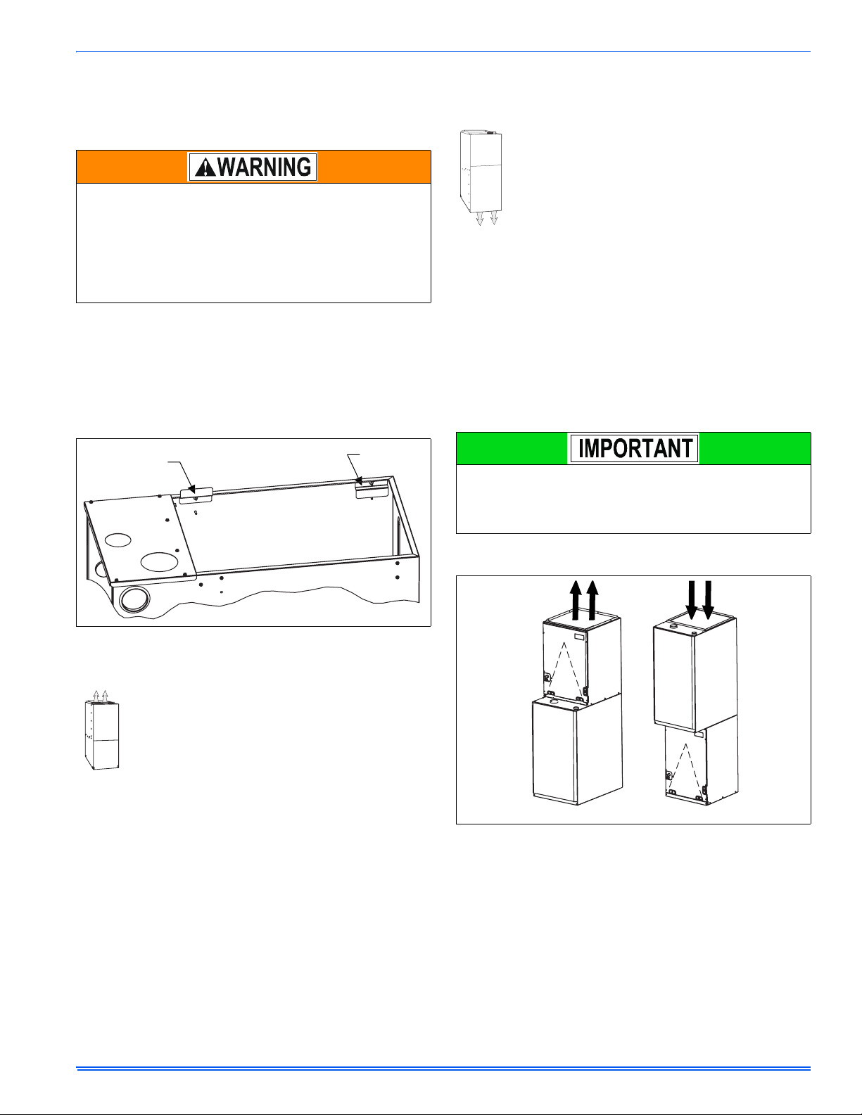
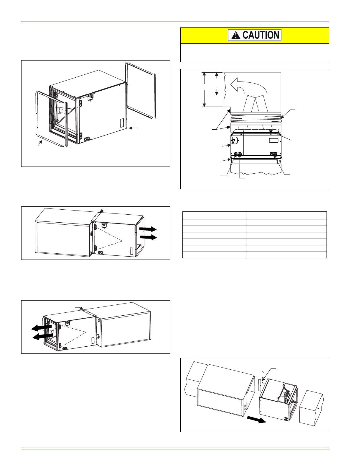
DUCT FLANGES
Four flanges are provided to attach ductwork to the furnace. These
flanges are rotated down for shipment. In order to use the flanges,
remove the screw holding an individual flange, rotate the flange so it is
in the upward position and reinstall the screw then repeat this for all 4
flanges.
If the flanges are not used, they must remain in the rotated down position as shipped.
For duct attachment,
if needed.
Factory
installed
FLOOR BASE AND DUCTWORK INSTALLATION DOWNFLOW
Installations on combustible material or directly on any
floors must use a combustible floor base shown in Figure 8,
"Combustible Floor Base Accessory". Follow the instructions supplied with the combustible floor base accessory.
This combustible floor base can be replaced with a matching cooling coil, properly sealed to prevent leaks. Follow the
instructions supplied with the cooling coil cabinet for installing the cabinet to the duct connector. Plug intake and vent
pipe holes in bottom panel and move grommet to desired
vent side exit.
Downflow Air Conditioning Coil Cabinet
The furnace should be installed with coil cabinet part number specifically intended for downflow application. If a matching cooling coil is
used, it may be placed directly on the furnace outlet and sealed to prevent leakage. For details of the coil cabinet dimensions and installation
requirements, refer to the installation instructions supplied with the coil
cabinet.
Attach the air conditioning coil cabinet to the duct connector, and then
position the furnace on top of the coil cabinet. The connection to the furnace, air conditioning coil cabinet, duct connector, and supply air duct
must be sealed to prevent air leakage.
COIL INSTALLATION
On all installations without a coil, a removable access panel is recommended in the outlet duct such that smoke or reflected light
would be observable inside the casing to indicate the presence of
leaks in the heat exchanger. This access cover shall be attached in
such a manner as to prevent leaks.
FIGURE 1: Duct Attachment
DUCTWORK INSTALLATION AND SUPPLY PLENUM
CONNECTION - UPFLOW/HORIZONTAL
Attach the supply plenum to the furnace outlet. The use of
an approved flexible duct connector is recommended on all
installations. This connection should be sealed to prevent
air leakage. The sheet metal should be crosshatched to
eliminate any popping of the sheet metal when the indoor
fan is energized.
COIL/FURNACE ASSEMBLY - MC/FC/PC SERIES
COILS
Furnace
Furnace
UPFLOW
FIGURE 2: Vertical Applications
DOWNFLOW
FURNACE ASSEMBLY - MC & FC SERIES COILS
These coils are factory shipped for installation in either upflow or downflow applications with no conversion.
Position the coil casing over or under the furnace opening as shown in
Figure 2, "Vertical Applications" after configuring coil flanges as
required see “Coil Flange” section below.
Johnson Controls Unitary Products 5
364861-UIM-B-0708
COIL FLANGE INSTALLATION
The coils include removable flanges to allow proper fit up with furnaces
having various inlet and outlet flange configurations. The two flanges
are attached to the top of the coil in the factory during production. For
proper configuration of flanges refer to Figure 3, "Coil Flange".
Do not drill any holes or drive any screws into the front duct
flange on the coil in order to prevent damaging coil tubing. See
Figure 6, "PC Series Upflow Coil Installation"
C
(Min)
D
Flexible
Duct Collar
FACTORY
FLANGE
LOCATION
(Used for upflow
or horizontal
ALTERNATE
FLANGE LOCATION
(Used for downflow or
horizontal left installations)
right installations)
FIGURE 3: Coil Flange
FURNACE ASSEMBLY - MC SERIES COILS ONLY
MC coils are supplied ready to be installed in a horizontal position. A
horizontal pan is factory installed. MC coils should be installed in all horizontal applications with the horizontal drain pan side down.
Mounting Plate
Furnace
FIGURE 4: Horizontal Right Application
For horizontal left hand applications no conversion is required to an MC
coil when used with a downflow/horizontal furnace. A mounting plate,
supplied with every coil should always be installed on the side designated as top side. See Figures 4 & 5.
Mounting Plate
Furnace
FIGURE 5: Horizontal Left Application
FURNACE ASSEMBLY - PC SERIES COILS
These upflow coils are designed for installation on top of upflow furnaces only.
If the coil is used with a furnace of a different size, use a 45° transition
to allow proper air distribution through the coil.
1. Position the coil casing over the furnace opening as shown in Figure 6, "PC Series Upflow Coil Installation".
2. Place the ductwork over the coil casing flange and secure.
3. Check for air leakage between the furnace and coil casing and
seal appropriately.
Field
Fabricated
Ductwork
Upflow
Coil
Upflow
Furnace
Primary
Drain
Secondary
Drain
Do not drill
or Screw
this flange
Alternate
Drain Location
FIGURE 6: PC Series Upflow Coil Installation
Table 2: Coil Projection Dimensions - PC Series Coils
COIL SIZE DIMENSION “C” INCH
PC18 3-1/2
PC24 4-1/2
PC30, PC32, PC35 4-1/2
PC42, PC43, PC36, PC37 5-1/2
PC48 6-1/2
PC60 9
NOTE: Dimension “C” should be at least 2/3 of dimension “D”. See Figure 6, "PC Series Upflow Coil Installation"
CRITICAL COIL PROJECTION
The coil assembly must be located in the duct such that a minimum distance is maintained between the top of the coil and the top of the duct.
Refer to Table 6.
COIL / FURNACE ASSEMBLY - HC SERIES COILS
These coils are supplied ready to be installed in a right hand position or
a left hand position. When used in conjunction with a horizontal furnace
(blow through) application, the coil should be oriented with the opening
of the “A” coil closest to the furnace. See Figure 6.
NOTE: Each coil is shipped with an external tie plate that should be
used to secure the coil to the furnace. It should be installed on the back
side of the coil using the dimpled pilot holes. See Figure 6.
Use tie plate
supplied with coil
Gas Furnace
Air flow
FIGURE 7: Horizontal Left or Right application (Right Shown)
6 Johnson Controls Unitary Products
364861-UIM-B-0708
DOWNFLOW DUCT CONNECTORS
All downflow installations must use a suitable duct connector approved
by the furnace manufacturer for use with this furnace. The duct connectors are designed to be connected to the rectangular duct under the
floor and sealed. Refer to the instructions supplied with the duct connector for proper installation. Refer to the separate accessory parts list
at the end of these instructions for the approved accessory duct connectors.
FURNACE
WARM AIR PLENUM
WITH 1” FLANGES
FIBERGLASS
INSULATION
FIBERGLASS TAPE
UNDER FLANGE
COMBUSTIBLE FLOOR
BASE ACCESSORY
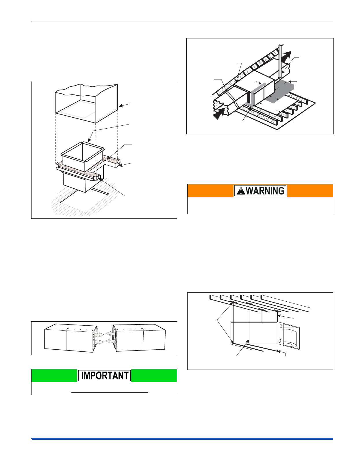
ATTIC INSTALLATION
Line contact only permissible
between lines formed by the
intersection of furnace top
and two sides and building
joists, studs or framing
Filter rack
must be a minimum
distance
of 18” (45.7 cm)
from the
furnace
Return
Air
Gas Piping
Sediment
Trap
30” MIN.
Work Area
FIGURE 10: Typical Attic Installation
This appliance is certified for line contact when the furnace is installed
in the horizontal left or right position. The line contact is only permissible
between lines that are formed by the intersection of the top and two
sides of the furnace and the building joists, studs or framing. This line
may be in contact with combustible material. Refer to Figure 10, "Typical Attic Installation".
When a furnace is installed in an attic or other insulated space,
keep all insulating materials at least 12 inches (30.5 cm) away from
furnace and burner combustion air openings.
12”
12”
Supply
Air
Vent (Maintain
required
clearances to
combustibles)
Sheet metal in
front of furnace
combustion air
Openings is
Recommended
FIGURE 8: Combustible Floor Base Accessory
RESIDENTIAL AND MODULAR HOME UPFLOW
RETURN PLENUM CONNECTION
Return air may enter the furnace through the side(s) or bottom depending on the type of application. Return air may not be connected into the
rear panel of the unit.
BOTTOM RETURN AND ATTIC INSTALLATIONS
Bottom return applications normally pull return air through a base platform or return air plenum. Be sure the return platform structure or return
air plenum is suitable to support the weight of the furnace.
The internal bottom panel must be removed for this application.
Attic installations must meet all minimum clearances to combustibles
and have floor support with required service accessibility.
HORIZONTAL APPLICATION
FIGURE 9: Horizontal Application
This furnace may be installed in a horizontal position on either side
as shown above. It must not be installed on its back.
SUSPENDED FURNACE / CRAWL SPACE
INSTALLATION
The furnace can be hung from floor joists or installed on suitable blocks
or pad. Blocks or pad installations shall provide adequate height to
ensure the unit will not be subject to water damage. Units may also be
suspended from rafters or floor joists using rods, pipe angle supports or
straps. Angle supports should be placed at the supply air end and near
the blower deck. Do not support at return air end of unit. All four suspension points must be level to ensure quite furnace operation. When
suspending the furnace use a secure platform constructed of plywood
or other building material secured to the floor joists. Refer to for typical
crawl space installation.
Angle Iron
Bracket
6” Min. Between
Rod & Front of Furnace
1” Max. Between
Rod & Back of Furnace
FIGURE 11: Typical Suspended Furnace / Crawl Space Installation
Support
Bracket
Johnson Controls Unitary Products 7
364861-UIM-B-0708
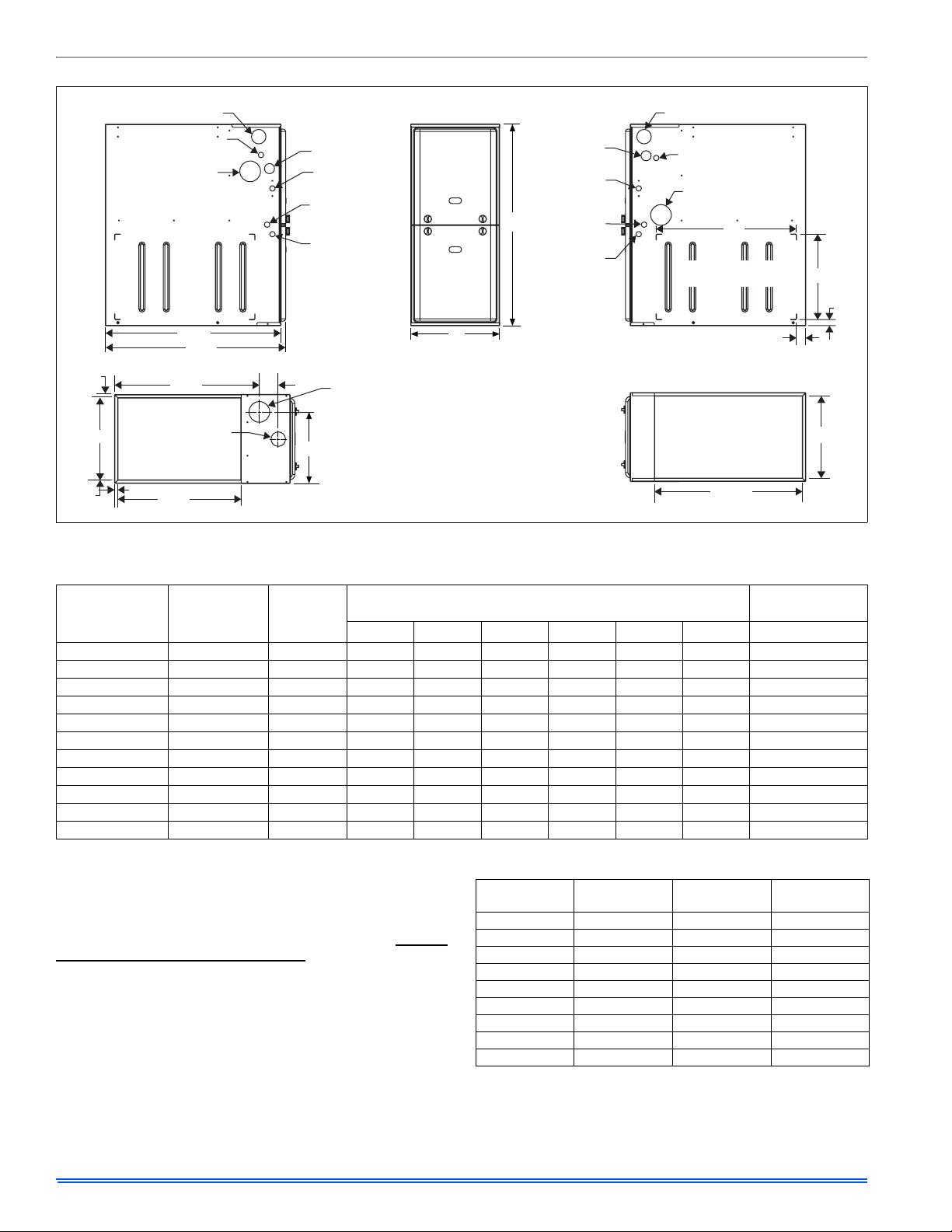
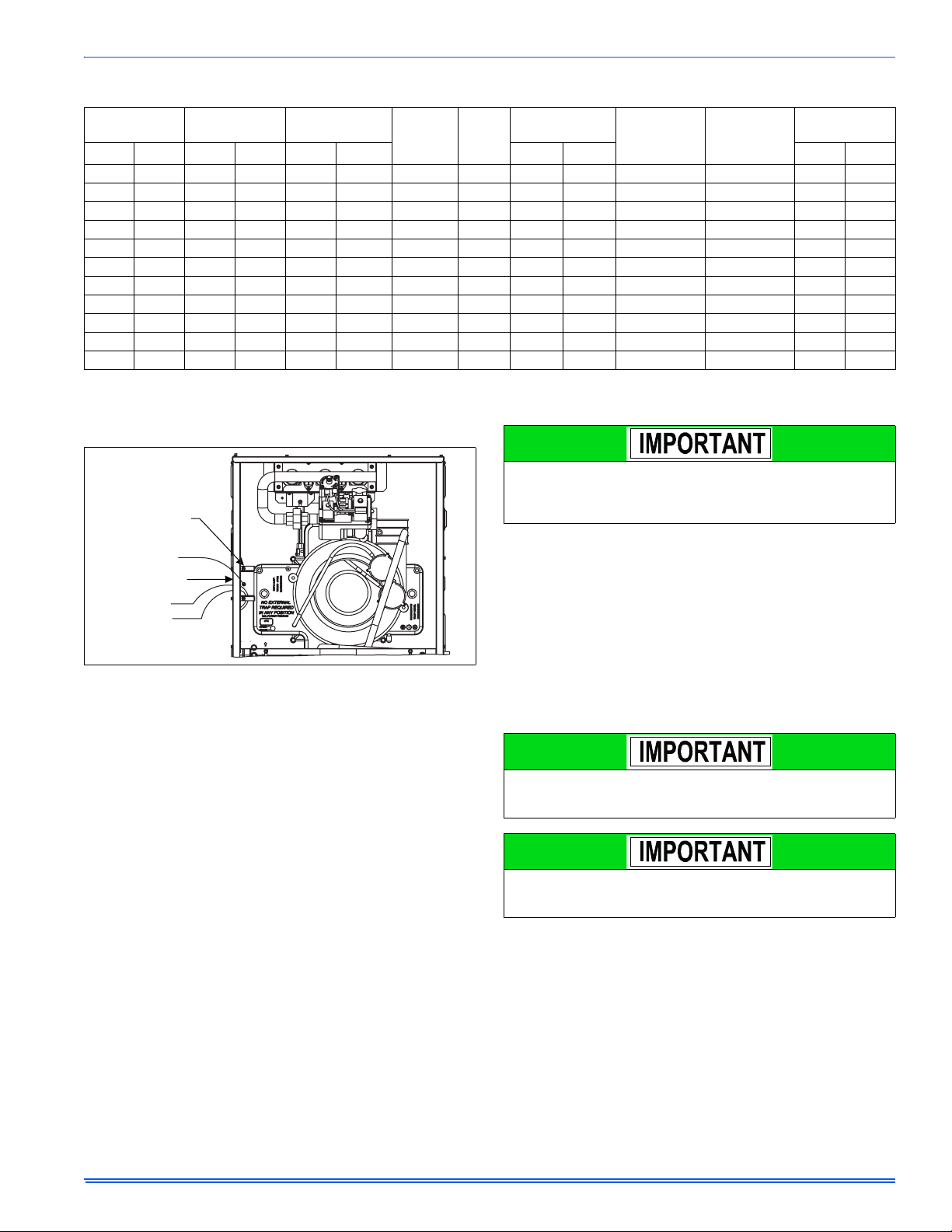
LEFT SIDE
Combustion Air Inlet
Condensate Drain
(Downflow)
Vent Outlet
28.5”
(For Cladded door add appoximately an additional .75”)
.56”
B
.56”
.56”
SUPPLY END
29.5”
23.8”
Combustion
Air Inlet
20”
3”
FIGURE 12: Dimensions
Gas Pipe
Entry
Electrical
Entry
Condensate
Drain
Thermostat
Wiring
Vent
Outlet
C
FRONT
A
33
Gas Pipe
Entry
Electrical
Entry
Condensate
Drain
Thermostat
Wiring
RIGHT SIDE
Combustion Air Inlet
Condensate Drain
(Downflow)
Vent Outlet
23”
Optional Return Air
Cutout (Either side)
24.25”
RETURN END
14”
1”
1.5”
B
Table 3: Cabinet and Duct Dimensions
BTUH (kW)
Input
Nominal
CFM (m
3
/min)
Cabinet
Size
AA (cm)BB (cm)CC (cm) Lbs
Cabinet Dimensions (Inches)
40 (11.7) 800 (22.7) A 14 1/2 36.8 13 3/8 34.0 11 3/4 29.8 113
60 (17.6) 1000 (28.3) A 14 1/2 36.8 13 3/8 34.0 11 3/4 29.8 118
60 (17.6) 1200 (34.0) B 17 1/2 44.4 16 3/8 41.6 13 1/4 33.7 122
80 (23.4) 1200 (34.0) B 17 1/2 44.4 16 3/8 41.6 14 3/4 37.5 126
80 (23.4) 1600 (45.3) C 21 53.3 19 7/8 50.5 16 1/2 41.9 136
80 (23.4) 2200 (62.3) C 21 53.3 19 7/8 50.5 16 1/2 41.9 139
100 (29.3) 1600 (45.3) C 21 53.3 19 7/8 50.5 18 1/4 46.4 142
100 (29.3) 2000 (56.6) C 21 53.3 19 7/8 50.5 18 1/4 46.4 145
120 (35.1) 1600 (45.3) D 24 1/2 62.2 23 3/8 59.4 21 3/4 55.2 153
120 (35.1) 2000 (56.6) D 24 1/2 62.2 23 3/8 59.4 21 3/4 55.2 156
130 (38.1) 2000 (56.6) D 24 1/2 62.2 23 3/8 59.4 No Hole No Hole 160
SECTION III: FILTERS
FILTER INSTALLATION
All applications require the use of a field installed filter. All filters and
mounting provision must be field supplied.
Filters must be installed external to the furnace cabinet. DO NOT
attempt to install filters inside the furnace.
NOTE: Single side return above 1800 CFM is approved as long as the
filter velocity does not exceed filter manufacturer’s recommendation
and a transition is used to allow use on a 20x25 filter.
Table 4: Recommended Filter Sizes (High Velocity 600 FPM)
CFM
(m³/min)
Cabinet
Size
Side
(in)
800 (22.7) A 16 x 25 14 x 25
1000 (28.3) A 16 x 25 14 x 25
1200 (34.0) A 16 x 25 14 x 25
1200 (34.0) B 16 x 25 16 x 25
1600 (45.3) B 16 x 25 16 x 25
1600 (45.3) C 16 x 25 20 x 25
2000 (56.6) C (2) 16 x 25 20 x 25
2200 (62.3) C (2) 16 x 25 20 x 25
2000 (56.6) D (2) 16 x 25 22 x 25
NOTES:
1.Air velocity through throwaway type filters may not exceed 300 feet per
minute (91.4 m/min). All velocities over this require the use of high velocity
filters.
2.Do not exceed 1800 CFM using a single side return and a 16x25 filter. For
CFM greater than 1800, you may use two side returns or one side and the
bottom or one side return with a transition to allow use of a 20x25 filter.
Approximate
Operating Weights
Bottom
(in)
8 Johnson Controls Unitary Products
364861-UIM-B-0708
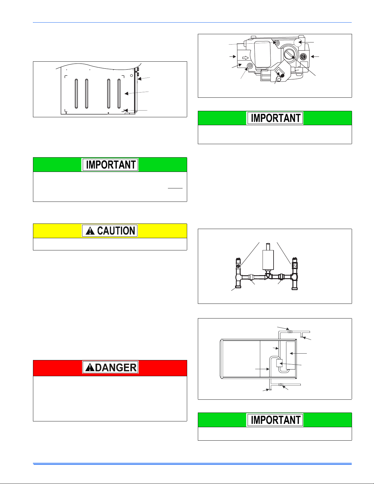
SIDE RETURN
Locate the “L” shaped corner locators. These indicate the size of the cutout to be made in the furnace side panel. Refer to Figure 13, "Side
Return Cutout Markings".
Front of
Furnace
Side of
Furnace
Corner
Markings
FIGURE 13: Side Return Cutout Markings
Install the side filter rack following the instructions provided with that
accessory. If a filter(s) is provided at another location in the return air
system, the ductwork may be directly attached to the furnace side
panel.
Some accessories such as electronic air cleaners and pleated
media may require a larger side opening. Follow the instructions
supplied with that accessory for side opening requirements. Do not
cut the opening larger than the dimensions shown in Figure 12,
"Dimensions".
HORIZONTAL APPLICATION
Horizontal Filters
Outlet
Pressure
Port
Inlet
Wrench
Boss
Inlet
Pressure
Port
FIGURE 14: Gas Valve
Plan your gas supply before determining the correct gas pipe entry.
Use 90-degree service elbow(s), or short nipples and conventional
90-degree elbow(s) to enter through the cabinet access holes.
On/Off Switch
(Shown in ON position)
OFF
ON
Vent Port
Outlet
Main Regulator
Adjustment
GAS PIPING INSTALLATION
Properly sized wrought iron, approved flexible or steel pipe must be
used when making gas connections to the unit. If local codes allow the
use of a flexible gas appliance connection, always use a new listed connector. Do not use a connector that has previously serviced another gas
appliance.
Some utility companies or local codes require pipe sizes larger than the
minimum sizes listed in these instructions and in the codes. The furnace
rating plate and the instructions in this section specify the type of gas
approved for this furnace - only use those approved gases. The installation of a drip leg and ground union is required. Refer to Figure 15,
"Upflow/Downflow Gas Piping".
All filters and mounting provision must be field supplied. All installations must have a filter installed.
Any branch duct (rectangular or round duct) attached to the plenum
must attach to the vertical plenum before the filter. The use of straps
and / or supports is required to support the weight of the external filte r
box.
Downflow Filters
Downflow furnaces typically are installed with the filters located above
the furnace, extending into the return air plenum or duct. Any branch
duct (rectangular or round duct) attached to the plenum must attach to
the vertical plenum above the filter height.
Filter(s) may be located in the duct system external to the furnace using
an external duct filter box attached to the furnace plenum or at the end
of the duct in a return filter grille(s). The use of straps and/or supports is
required to support the weight of the external filter box.
SECTION IV: GAS PIPING
GAS SAFETY
An overpressure protection device, such as a pressure regulator,
must be installed in the gas piping system upstream of the furnace
and must act to limit the downstream pressure to the gas valve so it
does not exceed 0.5 PSI (14" w.c. (3.48 kPa). Pressures exceeding
0.5 PSI (14” w.c. (3.48 kPa) at the gas valve will cause damage to
the gas valve, resulting in a fire or explosion or cause damage to
the furnace or some of its components that will result in property
damage and loss of life.
External Manual
Shutoff Valve
To Gas
Supply
Drip Leg
FIGURE 15: Upflow/Downflow Gas Piping
FIGURE 16: Horizontal Gas Piping
Grounded Joint Union
may be Installed
Inside or Outside Unit.
Manual
Shut-off
Valve
Gas
Pipe
Gas
Pipe
Drip
Leg
To Gas
Supply
Drip
Leg
Gas Burners
Gas Valve
Manual
Shut-off Valve
An accessible manual shutoff valve must be installed upstream of
the furnace gas controls and within 6 feet (1.8 m) of the furnace.
Johnson Controls Unitary Products 9
364861-UIM-B-0708
The furnace must be isolated from the gas supply piping system by
closing its individual external manual shutoff valve during any pressure
testing of the gas supply piping system at pressures equal to or less
than 1/2 psig (3.5 kPa).
The gas valve body is a very thin casting that cannot take any
external pressure. Never apply a pipe wrench to the body of the gas
valve when installing piping. A wrench must be placed on the octagon hub located on the gas inlet side of the valve. Placing a wrench
to the body of the gas valve will damage the valve causing improper
operation and/or the valve to leak.
Gas piping may be connected from either side of the furnace using any
of the gas pipe entry knockouts on both sides of the furnace. Refer to
Figure 12, "Dimensions".
Table 5: Nominal Manifold Pressure - High Fire
Manifold Pressures (in wc) Manifold Pressures (kpa)
Altitude (feet) Altitude (m)
0-7999 8000-8999 9000-9999 0-2437 2438-2742 2743-3048
800 3.5 3.5 3.5
850 3.5 3.5 3.5 31.7 0.87 0.87 0.87
900 3.5 3.5 3.5 33.5 0.87 0.87 0.87
950 3.5 3.5 3.3 35.4 0.87 0.87 0.81
1000 3.5 3.2 2.9 37.3 0.87 0.80 0.73
(BTU/cu ft.)
Gas Heating Value
1050 3.5 2.9 2.7 39.1 0.87 0.73 0.67
1100 3.2 2.7 2.4 41.0 0.80 0.66 0.61
2500 (LP) 9.8 8.2 7 .5 93.2 (LP) 2.44 2.03 1.86
GAS ORIFICE CONVERSION FOR PROPANE (LP)
This furnace is constructed at the factory for natural gas-fired operation,
but may be converted to operate on propane (LP) gas by using a factory-supplied LP conversion kit. Follow the instructions supplied with
the LP kit.
HIGH ALTITUDE GAS ORIFICE CONVERSION
This furnace is constructed at the factory for natural gas-fired operation
at 0 –5,000 feet (0-m – 1,524 m) above sea level.
The manifold pressure must be changed in order to maintain proper
and safe operation when the furnace is installed in a location where the
altitude is greater than 5,000 feet (1,524 m) above sea level. Refer to
Table 5, "Nominal Manifold Pressure - High Fire" for proper manifold
pressure settings.
HIGH ALTITUDE PRESSURE SWITCH CONVERSION
For installation where the altitude is less than 5,000 feet (1,524m), it is
not required that the pressure switch be changed unless you are in an
area subject to low pressure inversions.
29.8 0.87 0.87 0.87
(MJ/cu m)
Gas Heating Value
PROPANE AND HIGH ALTITUDE CONVERSION KITS
It is very important to choose the correct kit and/or gas orifices for the altitude and the type of gas for which the furnace is being installed.
Only use natural gas in furnaces designed for natural gas. Only use propane (LP) gas for furnaces that have been properly converted to use pro-
pane (LP) gas. Do not use this furnace with butane gas.
Incorrect gas orifices or a furnace that has been improperly converted will create an extremely dangerous condition resulting in premature heat
exchanger failure, excessive sooting, high levels of carbon monoxide, personal injury, property damage, a fire hazard and/or death.
High altitude and propane (LP) conversions are required in order for the appliance to satisfactory meet the application.
An authorized distributor or dealer must make all gas conversions.
In Canada, a certified conversion station or other qualified agency, using factory specified and/or approved parts, must perform the conversion.
The installer must take every precaution to insure that the furnace has been converted to the proper gas orifice size when the furnace is installed.
Do not attempt to drill out any orifices to obtain the proper orifice size. Drilling out a gas orifice will cause misalignment of the burner flames,
causing premature heat exchanger burnout, high levels of carbon monoxide, excessive sooting, a fire hazard, personal injury, property damage
and/or death.
SECTION V: ELECTRICAL POWER
ELECTRICAL POWER CONNECTIONS
Field wiring to the unit must be grounded. Electric wires that are field
installed shall conform to the temperature limitation for 63°F (35°C) rise
wire when installed in accordance with instructions. Refer to Table 6,
"Ratings & Physical / Electrical Data" in these instructions for specific
furnace electrical data.
Use copper conductors only.
10 Johnson Controls Unitary Products
364861-UIM-B-0708
Table 6: Ratings & Physical / Electrical Data
Input Output
MBH kW MBH kW CFM
Nominal
Airflow
m
3
/min
Total Unit
Amps
AFUE
%
Air Temp. Rise
°F °C °F °C
Max
Over-Current
Protect
Min. wire Size
(awg) @ 75 ft
one way
Max. Outlet
Air Temp
40 11.7 38 11.1 800 22.7 8.0 95.5 30-60 17-33 15 14 155 68.3
60 17.6 57 16.7 1000 28.3 10.0 95.5 30-60 19-36 15 14 155 68.3
60 17.6 57 16.7 1200 34.0 10.0 95.5 30-60 19-36 15 14 160 71.1
80 23.4 76 22.3 1200 34.0 10.0 95.5 35-65 19-36 15 14 165 73.9
80 23.4 76 22.3 1600 45.3 11.5 95.5 35-65 19-36 15 14 155 68.3
80 23.4 76 22.3 2200 62.3 17.0 95.5 35-65 19-36 20 12 155 68.3
100 29.3 95 27.8 1600 45.3 11.5 95.5 35-65 19-36 15 14 165 73.9
100 29.3 95 27.8 2000 56.6 17.0 95.5 35-65 19-36 20 12 155 68.3
120 35.1 114 33.4 1600 45.3 11.5 95.5 40-70 22-39 15 14 170 76.7
120 35.1 114 33.4 2000 56.6 17.0 95.5 35-65 19-36 20 12 160 71.1
130 38.1 123.5 36.2 2000 56.6 17.0 95.5 45-75 28-44 20 12 165 73.9
Annual Fuel Utilization Efficiency (AFUE) numbers are determined in accordance with DOE Test procedures.
Wire size and over current protection must comply with the National Electrical Code (NFPA-70-latest edition) and all local codes.
The furnace shall be installed so that the electrical components are protected from water.
SUPPLY VOLTAGE CONNECTIONS
The power connection leads and wiring box may be relocated to the
left side of the furnace. Remove the screws and cut wire tie holding
Junction
Box
Connect ground
lead to screw
Electrical Entry
BLK
L1-Hot
WHT
Neutral
FIGURE 17: Electrical Wiring
1. Provide a power supply separate from all other circuits. Install
overcurrent protection and disconnect switch per local/national
electrical codes. The switch should be close to the unit for convenience in servicing. With the disconnect or fused switch in the OFF
position, check all wiring against the unit wiring label. Refer to the
wiring diagram in this instruction.
2. Remove the screws retaining the wiring box cover. Route the
power wiring through the opening in the unit into the junction box
with a conduit connector or other proper connection. In the junction box there will be 3 wires, a Black Wire, a White Wire. Connect
the power supply as shown on the unit-wiring label on the inside of
the blower compartment door or the wiring schematic in this section. The black furnace lead must be connected to the L1 (hot)
wire from the power supply. The white furnace screw must be connected to neutral. Connect the power supply ground to the green
screw (equipment ground) An alternate wiring method is to use a
field provided 2” (5.1 cm) x 4” (10.2 cm) box and cover on the outside of the furnace. Route the furnace leads into the box using a
protective bushing where the wires pass through the furnace
panel. After making the wiring connections replace the wiring box
cover and screws. Refer to Figure 17, "Electrical Wiring".
3. The furnace's control system requires correct polarity of the power
supply and a proper ground connection. Refer to Figure 17, "Electrical Wiring"
excess wiring. Reposition on the left side of the furnace and fasten
using holes provided.
LOW VOLTAGE CONTROL WIRING CONNECTIONS
Install the field-supplied thermostat by following the instructions that
come with the thermostat. With the thermostat set in the OFF position
and the main electrical source disconnected, connect the thermostat
wiring from the wiring connections on the thermostat to the terminal
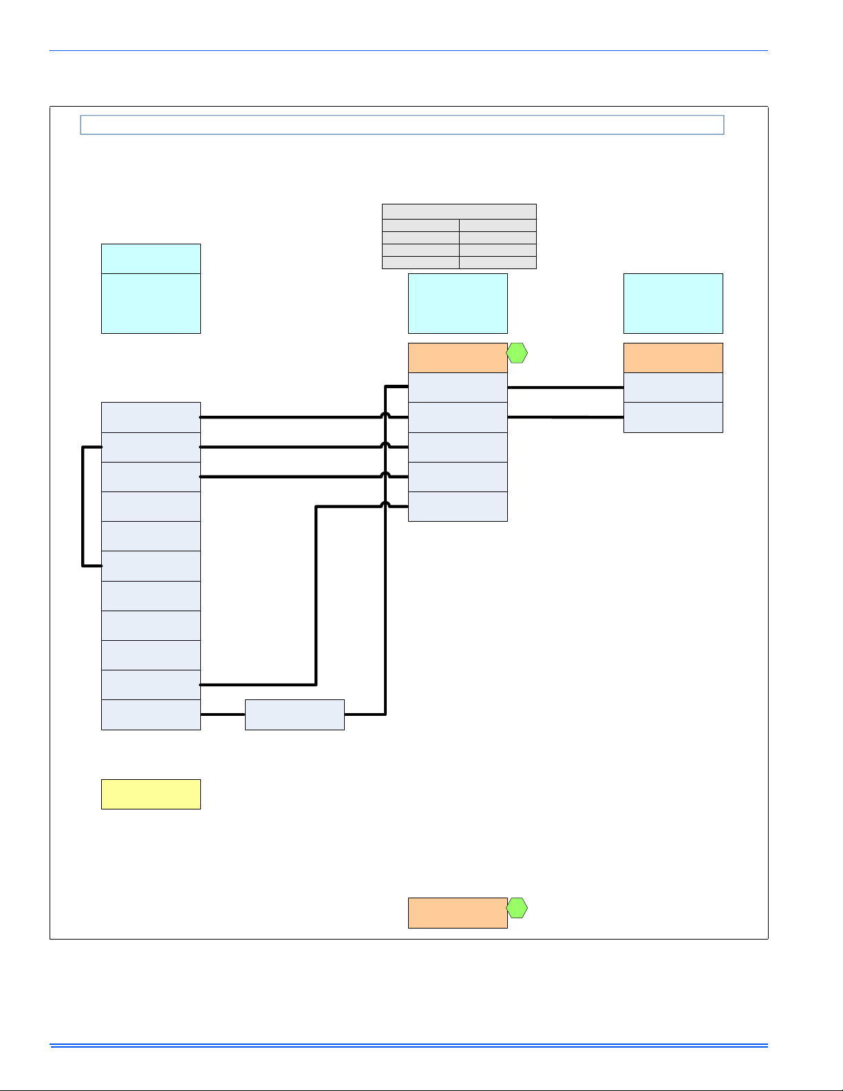
board on the ignition module, as shown in Figure 18, "Thermostat Chart
- Single Stage AC with Single Stage PSC Furnaces". Electronic thermostats may require the common wire to be connected. Apply strain relief
to thermostat wires passing through cabinet. If air conditioning equipment is installed, use thermostat wiring to connect the Y and C terminals on the furnace control board to the proper wires on the condensing
unit (unit outside).
Set the heat anticipator in the room thermostat to 0.4 amps. Setting
it lower will cause short cycles. Setting it higher will cause the room
temperature to exceed the set points.
Some electronic thermostats do not have adjustable heat anticipators. They should be set to six cycles per hour. Follow the thermostat manufacturer's instructions.
The 24-volt, 40 VA transformer is sized for the furnace components
only, and should not be connected to power auxiliary devices such as
humidifiers, air cleaners, etc. The transformer may provide power for an
air conditioning unit contactor.
Johnson Controls Unitary Products 11
364861-UIM-B-0708
For additional connection diagrams for all UPG equipment refer to “Low Voltage System Wiring” document available on-line at www.upgnet.com in
the Product Catalog Section.
AC 5D Single Stage Air Conditioner – Single Stage PSC Furnace
ID MODELS
THERMOSTAT
G*(8/9)S
G*9F
L(Y/M)8S
G8C
GF(8/9)
LF8
(G,T)G(8/9)S
(G/T)GLS
*PP11C70224
Y
Full Stage Compressor
RH
24 – Volt Hot
(Heat XFMR)
G
Fan
RC
24 – Volt Hot
(Cool XFMR)
W
Full Stage Heat
HM1
Humidistat
24VAC Humidifier
(Optional)
SINGLE STAGE
PSC
FURNACE
SINGLE STAGE PSC
FURNACE
C
24 – Volt Common
Y/Y2
Full Stage Compressor
R
24 – Volt Hot
G
Fan
W
Full Stage Heat
SINGLE STAGE
AIR
CONDITIONER
1
SINGLE STAGE
SINGLE STAGE
AIR CONDITIONER
AIR CONDITIONER
C
24 – Volt Common
Y
Y
Compressor
Compressor Contactor
Clipping Jumper W914 for
electric heat on thermostat
is not necessary
Other Part Numbers:
SAP = Legacy
265901 = 031-09166
1
FIGURE 18: Thermostat Chart - Single Stage AC with Single Stage PSC Furnaces
12 Johnson Controls Unitary Products
 Loading...