


T70, T115, and T165
Portable Space
Heaters
OPERATOR’S
MANUAL
FBL 156262
John Deere Merchandise Division
OMTY25047 Issue Nov-00
LITHO IN U.S.A.
ENGLISH/FRENCH

Introduction
THANK YOU for purchasing a John Deere product.
READ THIS MANUAL carefully to learn how to operate and service your machine correctly. Failure to do so could result in personal injury or equipment damage.
THIS MANUAL SHOULD BE CONSIDERED a permanent part of your machine and should remain with the machine when you sell it.
MEASUREMENTS in this manual are given in both metric and customary U.S. unit equivalents. Use only correct replacement parts and fasteners. Metric and inch fasteners may require a specific metric or inch wrench.
RIGHT-HAND AND LEFT-HAND sides are determined by facing in the direction the machine or implement will travel when going forward.
WRITE PRODUCT IDENTIFICATION NUMBERS (P.I.N.) in Serial Number Identification, page 25.
Accurately record all the numbers to help in tracing the machine should it be stolen. Your dealer also needs these numbers when you order parts. File the identification numbers in a secure place off the machine.
WARRANTY is provided as part of John Deere’s support program for customers who operate and maintain their equipment as described in this manual. The warranty is explained on the warranty certificate which you should have received from you dealer.
This warranty provides you the assurance that John Deere will back its products where defects appear within the warranty period. In some circumstances, John Deere also provides field improvements, often without charge to the customer, even if the product is out of warranty. Should the equipment be abused, or modified to change its performance beyond the original factory specifications, the warranty will become void and field improvements may be denied. Setting fuel delivery above specifications or otherwise overpowering machines will result in such action.
107351-01C

Contents
|
Page |
Safety ............................................................................. |
1 |
Operation |
|
Electrical Supply ............................................................. |
7 |
Filling Fuel Tank .............................................................. |
8 |
Extension Cords ............................................................. |
9 |
Ventilation ....................................................................... |
9 |
Starting Heater ............................................................. |
10 |
Heater Operation .......................................................... |
11 |
Stopping the Heater ...................................................... |
11 |
To Restart Heater ......................................................... |
11 |
Troubleshooting .......................................................... |
12 |
Periodic Service |
|
Additional Service Information ...................................... |
13 |
Using Service Records ................................................. |
13 |
Service Intervals |
|
150 Hours ............................................................... |
13 |
250 Hours ............................................................... |
13 |
500 Hours ............................................................... |
14 |
Yearly...................................................................... |
14 |
Draining Fuel Tank ........................................................ |
14 |
Cleaning Flame Sensor ................................................ |
15 |
Cleaning Air Intake Filter .............................................. |
15 |
Replacing Fuse ............................................................. |
16 |
Cleaning Fan ................................................................ |
16 |
Cleaning Fuel Nozzle ................................................... |
17 |
Fuel and Air Line Replacement and Proper Routing ...... |
18 |
Cleaning Fuel Filter ...................................................... |
19 |
Storage Location and Maintenance .............................. |
20 |
Assembly |
|
Unpack Components .................................................... |
21 |
Installing Nose Cone Guard ......................................... |
21 |
Attaching Wheels and Axle ........................................... |
22 |
Attaching Heater and Handles ...................................... |
23 |
Specifications ............................................................. |
24 |
Serial Number Identification ...................................... |
25 |
All information, illustrations and specifications in this manual are based on the latest information available at the time of publication. The right is reserved to make changes at any time without notice.
i |
107351-01C |
|

Contents
ii |
107351-01C |
|
Safety
RECOGNIZE SAFETY INFORMATION
This is the safety-alert symbol. When you see this symbol on your machine or in this manual, be alert to the potential for personal injury.
Follow recommended precautions and safe operating practices.
UNDERSTAND SIGNAL WORDS
A signal word —DANGER, WARNING, or CAUTION— is used with the safety-alert symbol. DANGER identifies the most serious hazards.
! DANGER
DANGER or WARNING safety signs are located near specific hazards. General precautions are listed on CAUTION safety signs. CAUTION also calls attention to safety messages in this manual.
 WARNING
 CAUTION
FOLLOW SAFETY INSTRUCTIONS
Carefully read all safety messages in this manual and on your machine safety signs. Keep safety signs in good condition. Replace missing or damaged safety signs. Be sure new equipment components and repair parts include the current safety signs. Replacement safety signs are available from your John Deere dealer.
Learn how to operate the machine and how to use controls properly. Do not let anyone operate without instruction.
Keep your machine in proper working condition. Unauthorized modifications to the machine may impair the function and/or safety and affect machine life.
If you do not understand any part of this manual and need assistance, contact your John Deere dealer.
 CAUTION WARNING
1 |
107351-01C |
|

SAFETY INFORMATION
 WARNINGS
WARNING: This product contains and/or generates chemicals known to the State of California to cause cancer or birth defects, or other reproductive harm.
IMPORTANT: Read this owner’s manual carefully and completely before trying to assemble, operate, or service this heater. Improper use of this heater can cause serious injury or death from burns, fire, explosion, electrical shock, and carbon monoxide poisoning.
 DANGER
Carbon monoxide poisoning may lead to death!
Early signs of carbon monoxide poisoning resemble the flu, with headaches, dizziness, and/or nausea. If you have these signs, the heater may not be working properly. Get fresh air at once! Have heater serviced. Some people are more affected by carbon monoxide than others. These include pregnant women, persons with heart or lung disease or anemia, those under the influence of alcohol, and those at high altitudes.
Make certain you read and understand all warnings. Keep this manual for reference. It is your guide to safe and proper operation of this heater.
•Use only kerosene or No. 1 fuel oil.
•Use only the electrical voltage and frequency specified on model plate.
•Heater must be grounded. Use only a properly grounded three-wire extension cord. Plug into grounded outlet only.
•Use only in areas free of flammable vapors or high dust content.
•Minimum clearances from any combustible materials: 8 feet (244 cm) from hot air outlet; 6 feet (183 cm) from top; and 4 feet (122 cm) from sides and inlet.
•Locate heater on a stable and level surface while hot or operating or a fire may occur.
•Use only in well-vented areas. Provide ventilation of at least three-square-feet (2,800 cm) for each 100,000 Btu/Hr (29.3 kW) of rating.
•Keep children and animals away from heater at all times.
•Never start heater when combustion chamber is hot or if fuel has accumulated in combustion chamber.
•Heater is equipped with a thermostat, heater may start anytime.
•When heater is moved or stored, it must be in a level position or fuel spillage may occur.
•Use heater only in accordance with local ordinances and codes.
•Never use gasoline, crankcase drainings, naphtha, paint thinners, alcohol, or other highly flammable fuels.
•Never use heater where gasoline, paint thinner, or other highly flammable vapors are present.
•Never use heater in living or sleeping areas.
•Never leave a heater plugged in without adult supervision if children or animals are likely to be present.
•Never move, handle, refuel, or service a hot, operating, or plugged-in heater.
•Never block air inlet (rear) or air outlet (front) of heater.
•Never attach duct work to front or rear of heater.
•Never attach heater to external fuel tank.
107351-01C
2
HANDLE FLUIDS SAFELY - AVOID FIRES
When you work around fuel, do not smoke or work near heaters or other fire hazards.
Store flammable fluids away from fire hazards. Do not incinerate or puncture pressurized containers.
Make sure machine is clean of trash, grease, and debris.
Do not store oily rags; they can ignite and burn spontaneously.
HANDLE FUEL SAFELY
The heater is designed to operate on kerosene or No. 1 fuel oil only. DO NOT use diesel fuel, No. 2 fuel oil, gasoline, crank case drainings, naphtha, paint thinner, alcohol, or other highly volatile fuels.
Toxic fumes could be created by using non-recommended fuels.
Do not add fuel to heater while it is hot, operating, or plugged in. Use only recommended fuel.
Do not smoke while refueling heater.
Avoid spilling fuel. Do not overfill fuel tank.
Wipe up any spilled fuel after refueling.
Move away from fueling area before operating heater.
Store in a level position when filled or fuel leakage may occur.
Do not use heater in the presence of flammable vapors such as paint, fuel, certain cleaning solvents, or high dust content.
IMPORTANT: Use a KEROSENE ONLY storage container. Be sure storage container is clean. Foreign matter such as rust, dirt, or water will cause the ignition control assembly to shut down the heater. Foreign matter may also require you to clean fuel system often.
3 |
107351-01C |
|
PREPARE FOR EMERGENCIES
Be prepared if a fire starts.
Keep a first aid kit and fire extinguisher handy.
Keep emergency numbers for doctors, ambulance service, hospital, and fire department near your telephone.
RESPECT ELECTRICITY
Make certain heater is properly grounded. Extension cord must be a 3-wire grounded cord and is of proper wire size for the length. Extension cord must be at least six feet (1.8 meters) long.
Make certain the connection between the power cord and the extension cord is not exposed to water.
Disconnect electrical plug before servicing or relocating heater.
Use heater only with 120-volt, AC, 60-hertz power source.
Use only on a fused circuit of proper voltage and frequency that is capable of handling the load.
107351-01C
4

 CAUTION
•Improper use of this heater can cause serious injury or death from burns, fire, explosion, electrical shock, and carbon monoxide poisoning.
•Use only kerosene or No. 1 fuel oil to avoid risk of fire or explosion. Never use gasoline, crankcase drainings, naphtha, paint thinners, alcohol, or other flammable fuels.
•Never use heater where gasoline, paint thinner, or other flammable vapors are present.
•Never use heater in areas with high dust content.
•Do not start heater when chamber is hot or if fuel has accumulated in chamber.
•Minimum heater clearances from combustible materials: Outlet: 8 Ft.: Sides: 4 Ft.: Top: 4 Ft.: Rear: 4 Ft.
•Heaters used in the vicinity of tarpaulins, canvas or similar enclosure materials shall be located a safe distance from such materials. The recommended minimum safe distance is 10 feet. It is further recommended that these enclosure materials be of a fire retardant nature. These enclosure materials shall be securely fastened to prevent them from igniting or from upsetting heater due to wind action.
•Use only a three-prong, grounded extension cord. Use only with the electrical voltage and frequency specified on model plate.
•Use only in well-ventilated areas. Provide at least a 3-square-foot opening of fresh, outside air for each 100,000 BTU/Hr of rating when running heater.
•Unplug heater when not in use.
•Never block air inlet (rear) or air outlet (front) of heater. Never attach duct work to front or rear of heater. Do not attach heater to external fuel tank.
•Locate heater on a stable and level surface while hot or running or a fire may occur.
•When moving or storing heater, keep heater in a level position or fuel spillage may occur.
•Never move, handle, refuel, or service a hot, operating, or pluggedin heater.
•Keep children and animals away from heater.
•Never use heater in living or sleeping areas.
•Follow all local ordinances and codes when using heater.
! WARNING: This heater is equipped with a thermostat.
Heater may start at any time.
FBL156262
098131-02
 ATTENTION
•Utiliser uniquement du kérosène ou du mazout n°1 pour éviter les risques d’incendie ou d’explosion. Ne jamais utiliser d’essence, d’huile de vidange, d’huile de naphte, du solvant pour peinture, de l’alcool ou d’autres combustibles inflammables.
•Ne jamais utiliser l’appareil de chauffage dans un endroit où de l’essence, du solvant pour peinture ou d’autres vapeurs inflammables sont présents.
•Ne jamais utiliser l’appareil de chauffage dans un endroit très poussiéreux.
•Ne pas mettre la chaufferette en marche lorsque la chambre de combustion est chaude ou que le combustible s’est accumulé dans la chambre de combustion.
•Distances minimales de l’appareil aux maté riaux combustibles: Sortie: 2,44 m (8 pi), Côtés: 1,22 m (4 pi), Dessus: 1,22 m (4 pi), Arrière: 1,22 m (4 pi)
•Les appareils utilisés à proximité de bâches, toiles ou matériaux d’enveloppement similaires doivent ê tre placé s à une distance sécuritaire de ces matériaux. La distance sé curitaire minimale recommandée est de 3,05 m (10 pi).
•En outre, il est conseillé que ces matériaux d’enveloppement soient ignifuges. Ils doivent en plus être bien fixé afin de les empêcher de prendre feu ou de renverser l’appareil de chauffage à cause des courants d’air.
•Utiliser uniquement un cordon prolongateur à trois broches avec mise à la terre. Utiliser exclusivement la tension et la fréquence électriques spécifiées sur la plaque signalétique.
•Utiliser l’appareil seulement dans des endroits bien ventilés. Prévoir une ouverture d’au moins 0,28 m2 (3 pi2) pour l’air frais extérieur pour chaque 29,3 kW (100 000 BTU/h) de capacité.
•Débrancher l’appareil quand il n’est pas en usage.
•Ne jamais bloquer l’entré e (arrière) ou la sortie (avant) d’air de l’appareil de chauffage. Ne jamais fixer de conduits à l’avant ou à l’arrière de l’appareil. Ne pas relier la chaufferette au réservoir de combustible extérieur.
•Placer l’appareil de chauffage sur une surface stable et plane quand il est chaud ou qu’il fonctionne pour éviter les incendies.
•Lors du dé placement ou du remisage de l’appareil de chauffage, le maintenir d’aplomb pour éviter les déversements de carburant.
•Ne jamais déplacer ni manipuler un appareil de chauffage chaud, en fonctionnement ou branché, et ne jamais en faire le plein ou l’entretien.
•Tenir les enfants et les animaux à l’écart de l’appareil.
•Ne jamais utiliser l’appareil de chauffage dans des locaux d’habitation ou des dortoirs.
•Respectez tous les règlements locaux et les normes régissant l’emploi de cet appareil.
! ADVERTISSEMENT: (Cet appareil de chauffage est é quipé d’un thermostat. Il risque de dé marrer à tout moment.)
 WARNING
 ATTENTION
Risk of fire or burns. Heater may ignite any time power cord is plugged in. Unplug power cord if heater is unattended.
Risque de feu ou de brû lures. Le radiateur peut s’allumer n’importe quand lorsque le cordon est branché . Dé brancher le cordon é lectrique lorsque le radiateur n’est pas surveillé .
 WARNING
 ATTENTION
Hot surfaces. Do not touch or move while burner is ignited or hot. Allow to cool and unplug heater before fueling.
Surfaces chaudes. ne pas toucher ou dé placer alors que le brû leur est allumé ou chaud. Laissez refroidir et dé branchez
le radiateur avant d’alimenter en combus-
098129-02
5 |
107351-01C |
|
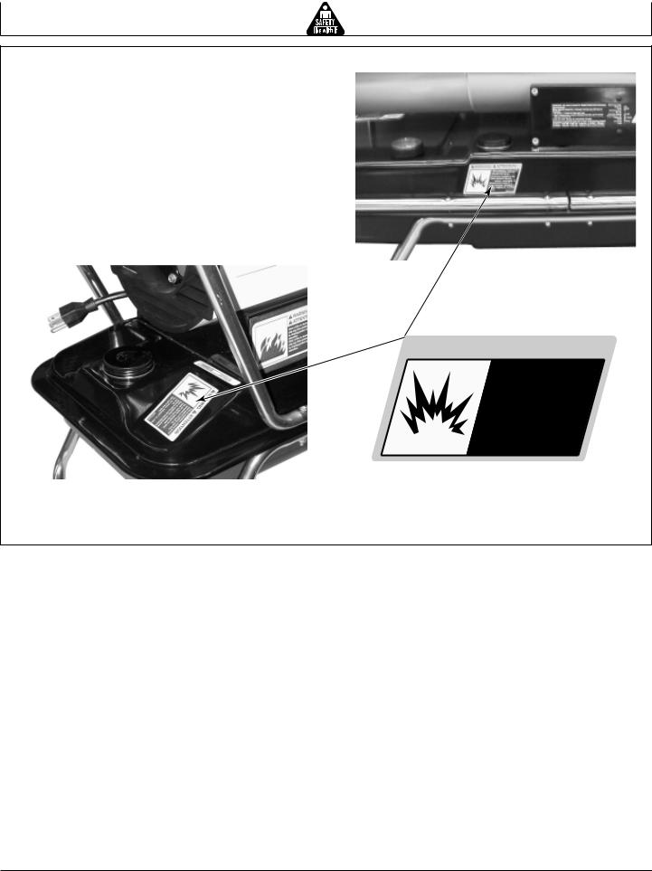
Model T115 and T165
 WARNING
  ATTENTION
Risk of explosion. Unplug power cord before fueling. Use only kerosene or #1 fuel oil.
Do not store, transport or ship heater with fuel in the tank.
Utiliser uniquement du ké rosè ne ou du carburant No. 1.
Ne pas entreposer, transporter ou expé dier le ré chaud lorsqu’il y a du carburant dans le ré servoir.
098134-02
Model T70
107351-01C
6
Operation
ELECTRICAL SUPPLY
CAUTION: If an additional electrical outlet is needed to operate your heater, it should be installed by a qualified electrician and the installation should conform to the applicable codes and governing requirements.
The heater requires a grounded 120-volt, 60-hertz receptacle for a power source. If necessary, use an appropriate grounding adapter to connect to a twoprong receptacle. Check heater amperage requirements in Specifications, page 24 .
IMPORTANT: DO NOT overload circuit.
7 |
107351-01C |
|
Operation |
|
|
|
|
|
|
|
|
|
|
|
FILLING FUEL TANK |
|
|
|
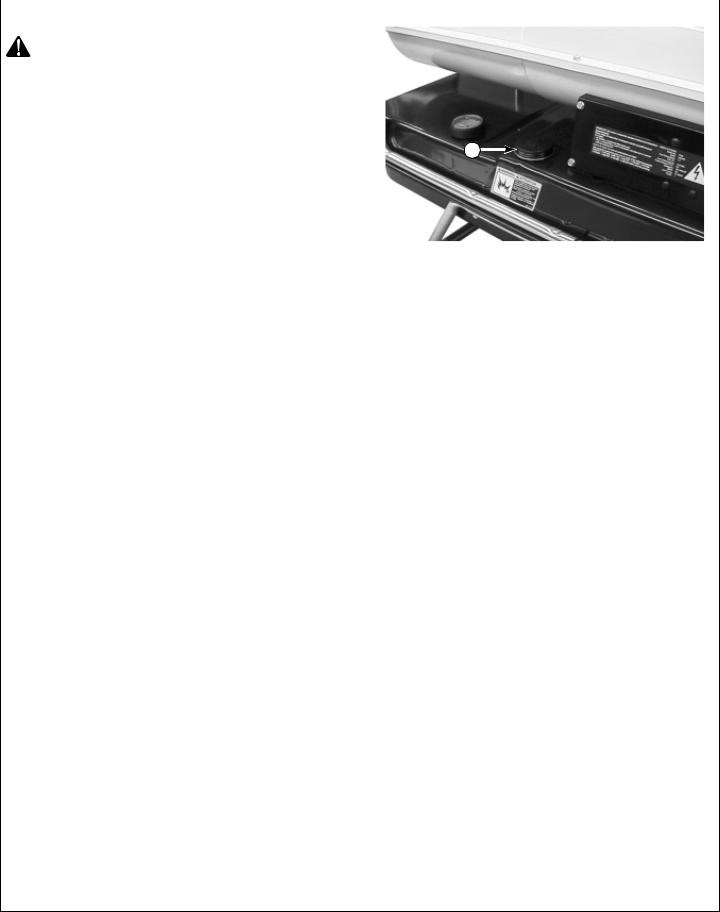
CAUTION: DO NOT add fuel while the heater is |
|
|
|
hot or operating. DO NOT use diesel, No. 2 fuel |
|
|
|
oil, gasoline, crank case drainings, naphtha, |
|
|
|
paint thinner, alcohol, or other highly volatile |
|
|
|
fuels.Toxic fumes could be created by using |
|
|
|
non-recommended fuels. |
|
|
|
Remove cap (A) from fuel tank and fill with kerosene |
A |
|
|
|
|||
or No. 1 fuel oil. |
|
|
|
Do not use heavy fuels such as No. 2 fuel oil or No. 2
Diesel. Using heavy fuels will result in:
•clogged fuel filter and nozzle due to fuel gelling
•carbon build up on spark plug
Do not use No. 3 fuel oil or heavy oils such as crank case drainings. These heavy oils will not ignite properly and will contaminate the heater.
Fueling
•Personnel involved with fueling shall be qualified and thoroughly familiar with the manufacturer’s instructions and applicable federal, state, and local regulations regarding the safe fueling of heating units.
•Only the type of fuel specified on the heater’s data plate shall be used.
•All flame, including the pilot light, if any, shall be extinguished and the heater allowed to cool, prior to fueling.
•During fueling, all fuel lines and fuel-line connections shall be inspected for leaks. Any leaks shall be repaired prior to returning the heater to service.
•At no time shall more than one day’s supply of heater fuel be stored inside a building in the vicinity of the heater. Bulk fuel storage shall be outside the structure.
•All fuel storage shall be located a minimum of 25 feet (7.62 m) from heaters, torches, welding equipment, and similar sources of ignition (exception: the fuel reservoir integral with the heater unit).
•Whenever possible, fuel storage shall be confined to areas where floor penetrations do not permit fuel to drip onto or be ignited by a fire at lower elevation.
•Fuel storage shall be in accordance with the federal, state, or local authority having jurisdiction.
107351-01C
8
Operation
EXTENSION CORDS
Plug heater’s power cord into approved, grounded, three-wire extension cord. Extension cord must be at least six feet (1.8 meters) long.
Extension Cord Size Requirement
6 to 10 feet (1.8 to 3 meters) long, use 18 AWG (0.75 mm2) rated cord
11 to 100 feet (3.3 to 30.5 meters) long, use 16 AWG (1.0 mm2) rated cord
101 to 200 feet (30.8 to 61 meters) long, use 14 AWG (1.5 mm2) rated cord
VENTILATION
WARNING: Provide a fresh, outside air opening of at least three square feet (2,800 square cm) for each 100,000 Btu/Hr (29.3 kW) rating. Provide extra fresh air if more heaters are being used. The minimum ventilation requirements must be followed to avoid risks associated with carbon monoxide poisoning. Make certain these requirements are met prior to operating heater.
Example: A 165,000 Btu/Hr (48.35 kW) heater requires one of the following:
•a two-car garage door (16 feet [4.88 m] wide opening) raised four inches (10.16 cm)
•a single-car garage door (9 feet [2.74 m] wide opening) raised seven inches (17.78 cm)
•two, thirty inch (76.20 cm) windows raised twelve inches (30.48 cm)
9 |
107351-01C |
|
Operation
STARTING HEATER
CAUTION: Observe the following:
•Provide a minimum of 3 square feet (0.28 m2) of ventilating area per 100,000 BTU (29.3 kW). If more than one heater is used, include equivalent ventilating area.
•Provide adequate clearance from people, animals, and combustible materials - 8 feet (2.4 m) from heater outlet; 6 feet (1.8 m) from top; 4 feet (1.2 m) from sides.
•Be sure there is no obstruction in intake or output openings.
•Be sure heater is on a level, stable surface.
•Depending on thermostat setting, heater can start immediately when power cord is connected.
•Be sure electrical circuit is adequate and properly grounded.
•Locate heater to provide maximum circulation of the heated air.
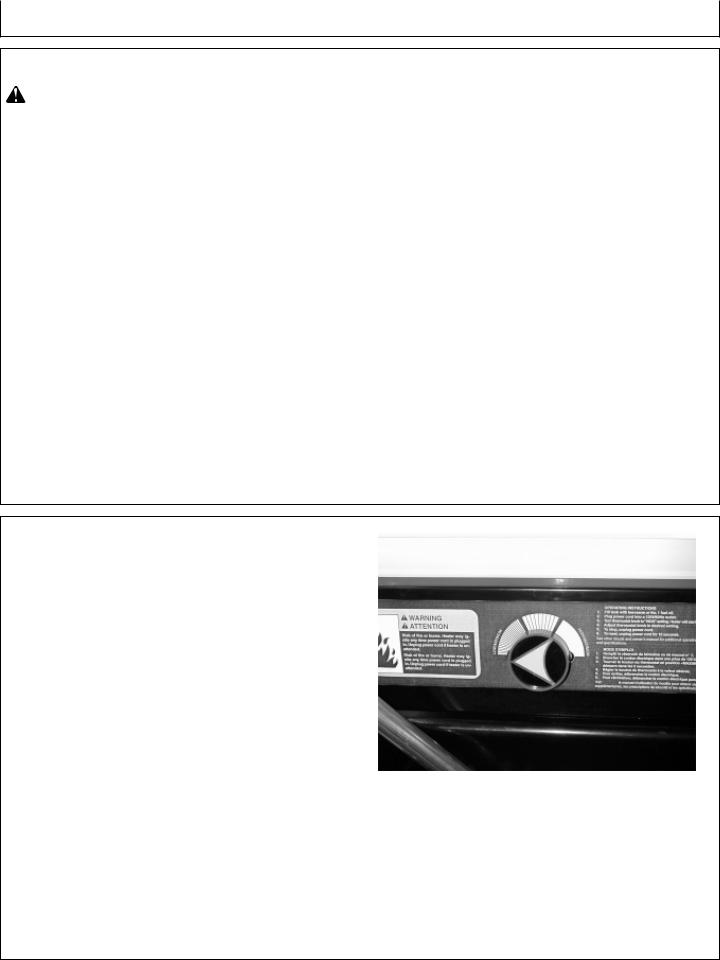
1.Turn thermostat knob clockwise to the high position.
2.Plug extension cord into standard 120 volt/60 hertz, 3-prong grounded outlet. Note: Ignitor will preheat for five seconds, then heater will start.
3.Adjust thermostat knob to the desired setting. Note: A cold heater may affect the thermostat setting. This thermostat is a general-heating control. It is not intended for precise temperature control. Adjust thermostat until heater cycles at the desired setting.
Note: If heater fails to start, refer to Troubleshooting, page 12.
107351-01C
10
Operation
HEATER OPERATION
The space heater will cycle on and off to maintain the temperature set at the thermostat. To determine a specific temperature, place a thermometer to the sides or rear of the heater 4 - 6 feet (1.2 - 1.8 m) above the floor.
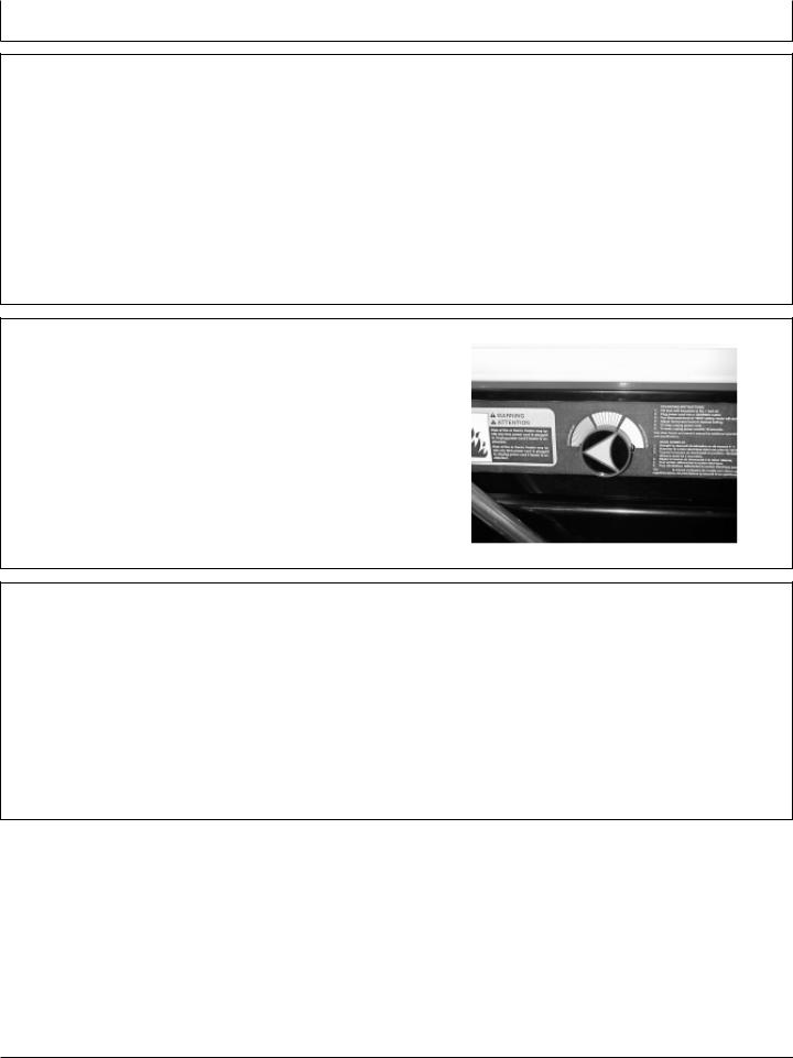
STOPPING THE HEATER
1.Set thermostat to lowest setting. Heater will stop, but will start again when ambient temperature drops to that setting.
2.To completely stop the heater, disconnect the plug from the receptacle.
TO RESTART HEATER
1.Unplug extension cord from outlet and wait 10 seconds. (Wait two minutes if heater has been running.)
2.Repeat steps under Starting Heater, page 10.
11 |
107351-01C |
|

Troubleshooting
DIAGNOSE MALFUNCTIONS
Symptom
Motor does not start five seconds after heater is plugged in
WARNING: Never service heater while it is plugged in, operating, or hot. Severe burns and electrical shock can occur.
Problem
No power to heater
Thermostat setting is too low
WARNING: High voltage!
Bad electrical connection between motor and ignition control assembly or ignition control assembly and power cord
Solution
Check circuit breaker in electrical panel Turn thermostat knob to a higher setting
Check all electrical connections
|
Binding pump rotor |
See your John Deere dealer |
|
Defective ignition control assembly |
See your John Deere dealer |
|
Defective motor |
See your John Deere dealer |
|
|
|
Motor starts and runs but |
No fuel in tank |
Fill tank with kerosene |
heater does not ignite |
Pump pressure incorrect |
See your John Deere dealer |
|
||
|
Dirty fuel filter |
See Cleaning Fuel Filter, page 19 |
|
Obstruction in nozzle assembly |
See Cleaning Fuel Nozzle, page 17 |
|
Water in fuel tank |
Drain and flush fuel tank with clean |
|
|
kerosene. See Storage Location and |
|
|
Maintenance, page 20 |
|
WARNING: High voltage! |
|
|
Bad electrical connection between |
Check electrical connections |
|
ignitor and ignition control assembly |
|
|
Defective ignitor |
See your John Deere dealer |
|
Defective ignition control assembly |
See your John Deere dealer |
|
|
|
Heater ignites but ignition |
Pump pressure incorrect |
See your John Deere dealer |
control assembly shuts heater |
|
|
off after a short period of time |
Dirty air intake, air output, and/or lint |
See your John Deere dealer |
|
filter |
|
|
Dirty fuel filter |
See Cleaning Fuel Filter, page 19 |
|
Obstruction in nozzle assembly |
See Cleaning Fuel Nozzle, page 17 |
|
Photocell assembly not properly |
Make sure photocell boot is properly |
|
installed (not seeing the flame) |
seated in bracket |
|
Dirty flame sensor |
See Cleaning Flame Sensor, page 15 |
|
WARNING: High voltage! |
|
|
Bad electrical connection between |
Check electrical connections |
|
photocell and ignition control assembly |
|
|
Defective flame sensor |
See your John Deere dealer |
|
Defective ignition control assembly |
See your John Deere dealer |
107351-01C
12
Periodic Service
ADDITIONAL SERVICE INFORMATION
This manual is not a detailed service manual. It has only information you need for normal operation and maintenance.
If a technical manual is desired, see your John Deere dealer for the correct manual.
USING SERVICE RECORDS
1.Keep a record of the number of hours or operation.
2.Check your record regularly to learn when service is required.
3.Do all the services in the interval section. Then write the number of hours (from your service record) and the date in the spaces provided.
Sample Service Record Chart
Date |
Hours |
|
|
1 Jun '85 |
3 |
|
|
6 Jun '85 |
2 - (5) |
|
|
7 Jun '85 |
1 - (6) |
|
|
11 Jun '85 |
4 - (10) |
|
|
17 Jun '85 |
3 - (13) |
|
|
150 HOURS |
|
|
|
|
|
|
Hours |
|
|
|
|
|
|
Drain Fuel Tank. |
Date |
|
|
|
|
|
Hours |
|
|
|
|
|
|
|
|
|
|
|
|
|
|
Date |
|
|
|
|
|
|
Hours |
|
|
|
|
|
|
Date |
|
|
|
|
|
|
Hours |
|
|
|
|
|
|
Date |
|
|
|
|
|
|
Hours |
|
|
|
|
|
|
Date |
|
|
|
|
|
|
|
|
|
|
|
|
|
|
|
|
|
|
|
250 HOURS |
|
|
|
|
|
|
Hours |
|
|
|
|
|
|
|
|
|
|
|
|
|
Clean flame sensor. |
Date |
|
|
|
|
|
Clean air intake filter. |
Hours |
|
|
|
|
|
Date |
|
|
|
|
|
|
|
|
|
|
|
|
|
Clean fan. |
Hours |
|
|
|
|
|
|
Date |
|
|
|
|
|
|
Hours |
|
|
|
|
|
|
Date |
|
|
|
|
|
|
Hours |
|
|
|
|
|
|
Date |
|
|
|
|
|
|
|
|
|
|
|
|
13 |
107351-01C |
|
Periodic Service
500 HOURS
Clean flame sensor.
Clean air intake filter.
Clean fan.
Clean fuel filter.
Replace air output and lint filters. See your John Deere dealer for service.
Hours
Date
Hours
Date
Hours
Date
Hours
Date
Hours
Date
YEARLY
Clean fuel nozzle. Drain fuel tank. Clean fuel filter. Clean flame sensor. Clean air intake filter. Clean fan.
Hours
Date
Hours
Date
Hours
Date
Hours
Date
Hours
Date
CAUTION: Before performing service, disconnect power cord from electrical outlet. Failure to unplug heater could cause serious injury.
Allow heater time to cool. Severe burns and electrical shock can occur.
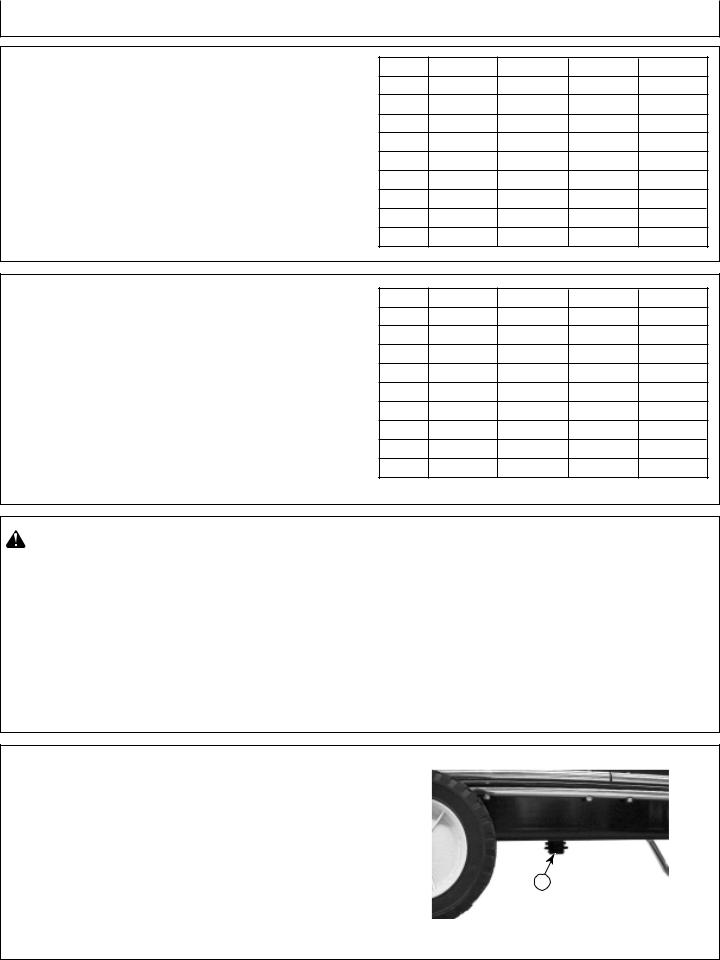
DRAINING FUEL TANK
1.Remove drain plug (A).
2.Drain and flush tank with clean fuel.
3.Replace drain plug.
A
107351-01C
14
Periodic Service
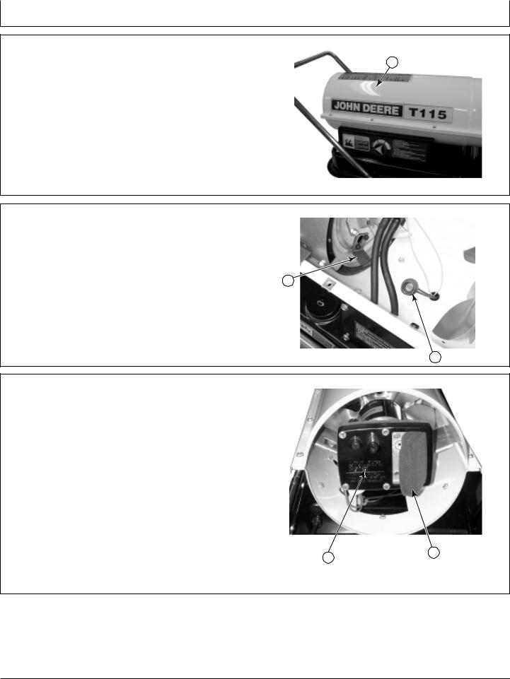
CLEANING FLAME SENSOR |
|
1. Remove upper shell (A) from heater by remov- |
A |
|
|
ing self-tapping screws. |
|
Note: Nose Cone Guard must be removed first on |
|
model T70. |
|
IMPORTANT: DO NOT bend flame sensor mounting bracket.
2.Remove sensor (A) from bracket (B) and clean
face of photocell with a soft cloth.
3.Insert sensor into bracket.
B
4.Install upper shell.
A
CLEANING AIR INTAKE FILTER
1.Remove upper shell and plastic fan guard.
2.Remove filter (A) from filter cover (B).
3.Clean filter in mild detergent and warm water. Dry thoroughly before reinstallation. Replace if needed.
IMPORTANT: DO NOT oil filter or pump.
There are two other filters inside the pump assembly; an air output filter and a lint filter. See your John Deere dealer for service.
B A
15 |
107351-01C |
|
Periodic Service
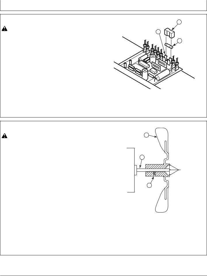
REPLACING FUSE
A
WARNING: High Voltage!
B
1.Unplug heater.
C
2. Remove side cover screws to expose ignition control assembly.
3. Remove fuse cover (A).
4. Remove fuse from fuse clips (B).
5. Replace fuse (C) with fuse of the same type and rating (GMA-10). Do not substitute a fuse with a higher current rating.
6.Replace fuse cover.
7.Replace side cover.
CLEANING FAN
CAUTION: Fan blades are sharp. Carefully work around blades or wear gloves when cleaning.
IMPORTANT: Remove fan from motor shaft before removing motor from heater. The weight of the motor resting on the fan could damage the fan pitch.
1.Remove upper shell and fan guard.
2.Loosen setscrew (A) which holds fan (B) to motor shaft (C).
3.Slip fan off motor shaft.
4.Clean fan using a soft cloth moistened with kerosene or solvent.
5.Dry fan thoroughly.
6.Replace fan on motor shaft. Place fan hub flush with end of motor shaft.
7.Place setscrew on flat of shaft. Tighten setscrew firmly (40 to 50 in-lbs/4.5 to 5.6 N-m).
8.Replace fan guard and upper shell.
B
C
Flush
A
107351-01C
16
Periodic Service
CLEANING FUEL NOZZLE
1.Remove upper shell and fan guard.
CAUTION: Fan blades are sharp. Carefully work around blades or wear gloves when removing or installing parts.
2.Remove fan.
3.Remove fuel line hose (A) and air line hose (B) from nozzle assembly (C).
4.Turn nozzle assembly 1/4 turn to left and pull toward motor to remove from burner strap (D).
5.Place plastic hex-body into vise and lightly tighten.
6.Carefully remove nozzle (A) from the nozzle adapter (B).
D
C
B
IMPORTANT: DO NOT clean nozzle passage with a wire or any other tool, or damage could result.
7. |
Blow compressed air through face of nozzle (D). |
|
This will free any dirt in nozzle area. |
|
|
8. |
Inspect nozzle seal (C) for damage. |
C |
CAUTION: If nozzle is not tightened, fuel will leak into lower shell causing a potential fire hazard.
9.Replace nozzle into nozzle adapter until nozzle seats. Tighten 1/3 turn more using 5/8" socket wrench (40 to 45 in-lbs/4.5 to 5.1 N-m).
10.Attach nozzle assembly to burner strap.
11.Attach fuel and airline hoses to nozzle assembly. See Fuel and Airline Replacement and Proper Routing, page 18.
12.Replace fan.
13.Replace fan guard and upper shell.
B
A
D
17 |
107351-01C |
|
 Loading...