


 Loading...
G0
Scotts Lawn Tractors
S1642, S1742, and S2046
OMGX10784 G0
OPERATOR’S MANUAL
North American Version
Litho in U.S.A.

INTRODUCTION
Thank You for Purchasing a Scotts Product
We appreciate having you as a customer and wish you many years of safe and satisfied use of your machine.
Using Your Operator’s Manual
This manual is an important part of your machine and should remain with the machine when you sell it.
Reading your operator’s manual will help you and others avoid personal injury or damage to the machine. Information given in this manual will provide the operator with the safest and most effective use of the machine. Knowing how to operate this machine safely and correctly will allow you to train others who may operate this machine.
Product warranty is provided as part of John Deere’s support program for customers who operate and maintain their equipment as described in this manual. The product warranty is explained on the warranty certification you received from your dealer.
Sections in your operator’s manual are placed in a specific order to help you understand all the safety messages and learn the controls so you can operate this machine safely. You can also use this manual to answer any specific operating or servicing questions. A convenient index located at the end of this book will help you to find needed information quickly.
The machine shown in this manual may differ slightly from your machine, but will be similar enough to help you understand our instructions.
RIGHT-HAND and LEFT-HAND sides are determined by facing in the direction the machine will travel when going forward. When you see a broken line arrow (------>), the item referred to is hidden from view.
Special Messages
Your manual contains special messages to bring attention to potential safety concerns, machine damage as well as helpful operating and servicing information. Please read all the information carefully to avoid injury and machine damage.
CAUTION: Avoid injury! This symbol and text highlight potential hazards or death to the operator or bystanders that may occur if the hazards or procedures are ignored.
IMPORTANT: Avoid damage! This text is used to tell the operator of actions or conditions that might result in damage to the machine.
NOTE: General information is given throughout the manual that may help the operator in the operation or service of the machine.
CALIFORNIA Proposition 65 Warning
 Warning:The Engine Exhaust from this product contains chemicals known to the State of California to cause cancer, birth defects or other reproductive harm.
Introduction
PRODUCT IDENTIFICATION
Record Identification Numbers
Scott’s Lawn Tractors
S1642, S1742 and S2046 PIN (020001 - )
If you need to contact an Authorized Service Center for information on servicing, always provide the product model and identification numbers.
You will need to locate the identification numbers for the product. Record the information in the spaces provided below.
 A
A 
M96453
PRODUCT IDENTIFICATION NUMBER (A):
__ __ __ __ __ __ __ __ __ __ __ __ __ __ __ __ __
 B
B 
M95201
Picture Note: 17hp engine shown.
ENGINE SERIAL NUMBER (B):
__ __ __ __ __ __ __ __ __ __ __ __ __ __ __ __ __
DATE OF PURCHASE:
_________________________________________
DEALER NAME:
_________________________________________
DEALER PHONE:
_________________________________________
Product Identification

|
TABLE OF CONTENTS |
Safety ..................................................................................................................................................................................... |
1 |
Operating................................................................................................................................................................................ |
8 |
Replacement Parts ............................................................................................................................................................... |
21 |
Service Intervals................................................................................................................................................................... |
22 |
Service Lubrication............................................................................................................................................................... |
23 |
Service Engine ..................................................................................................................................................................... |
24 |
Service Steering and Brakes ................................................................................................................................................ |
31 |
Service Mower...................................................................................................................................................................... |
33 |
Service Electrical.................................................................................................................................................................. |
40 |
Service Miscellaneous.......................................................................................................................................................... |
43 |
Troubleshooting .................................................................................................................................................................... |
45 |
Storage ................................................................................................................................................................................. |
49 |
Specifications ....................................................................................................................................................................... |
51 |
Assembly .............................................................................................................................................................................. |
54 |
Warranty ............................................................................................................................................................................... |
56 |
Index..................................................................................................................................................................................... |
60 |
All information, illustrations and specifications in this manual are based on the latest information at the time of publication. The right is reserved to make changes at any time without notice.
COPYRIGHT© 2000
Deere & Co.
John Deere Worldwide Commercial and
Consumer Equipment Division
Horicon, WI
All rights reserved
Previous Editions
COPYRIGHT© 1998, 1997
OMGX10784 G0 - English
Table of Contents

SAFETY
Understanding The Machine Safety Labels
The machine safety labels shown in this section are placed in important areas on your machine to draw attention to potential safety hazards.
On your machine safety labels, the words DANGER, WARNING, and CAUTION are used with this safety-alert symbol, ( ). DANGER identifies the most serious hazards.
The operator’s manual also explains any potential safety hazards whenever necessary in special safety messages that are identified with the word, CAUTION, and the safetyalert symbol, ( ).
DANGER-WARNING: AVOID SERIOUS INJURY OR DEATH
M96445
•Do not mow when children or others are around.
•Do not mow in reverse.
•Look down and behind before and while backing.
•Never carry children even with blades off.
•Drive up and down slopes, not across.
•Avoid sudden turns.
•If machine stops going uphill, stop blade and back down slowly.
•Keep safety devices (guards, shields, and switches) in place and working.
•Read operator’s manual.
•When leaving machine:
–Stop engine
–Set park brake
–Remove key
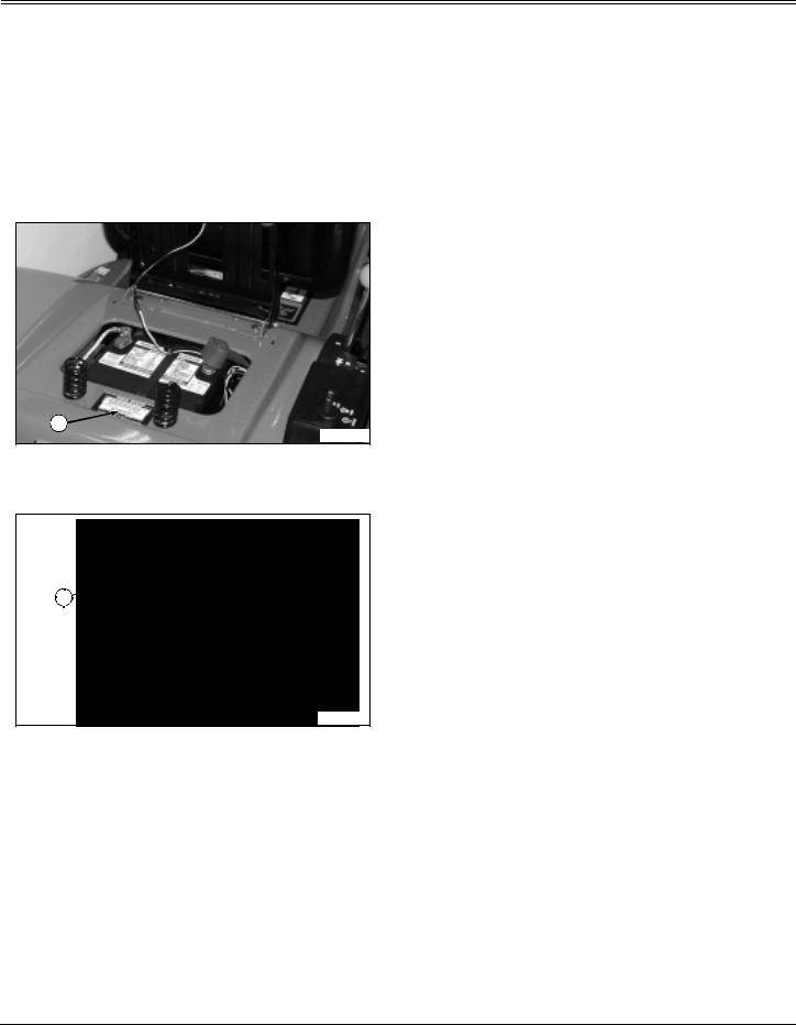
DANGER: POISON
M96445
Picture Note: Located on battery, under seat.
•Shield eyes. Explosive gases can cause blindness or injury.
•No sparks, flames, smoking.
•Sulfuric acid can cause blindness or severe burns.
•Flush eyes immediately with water.
•Get medical help fast.
•Keep out of the reach of children.
•Do not tip.
•Do not open battery!
Safety - 1

SAFETY
DANGER: ROTATING BLADE-THROWN OBJECTS
M96445
Picture Note: Located on Right-Hand side of deck
•Rotating blades.
•Do not put hands or feet under or into mower when engine is running.
•Thrown objects.
•Before mowing, clear area of objects that may be thrown by blade.
•Do not operate mower without discharge chute or entire grass catcher in place.
DANGER: ROTATING BLADE
M96445
Picture Note: Located on Left-Hand side of deck
• Do not put hands or feet under or into mower when engine is running.
Emission Control System Certification Label
NOTE: Tampering with emission controls and components by unauthorized personnel may result in severe fines or penalties. Emission controls and components can only be adjusted by EPA and/or CARB authorized service centers. Contact your John Deere Commercial and Consumer Equipment Retailer concerning emission controls and component questions.
The presence of an emissions label signifies that the engine has been certified with the United States Environmental Protection Agency (EPA) and/or California Air Resources Board (CARB).
The emissions warranty applies only to those engines marketed by John Deere that have been certified by the EPA and/or CARB; and used in the United States and Canada in off-road mobile equipment.
Emission Compliance Period
If your engine has the emission compliance category listed on the emission control system certification or air index label, this indicates the number of operating hours for which the engine has been certified to meet EPA and/or CARB emission requirements. The following table provides the engine compliance period in hours associated with the category found on the certification label.
Agency |
Category |
Hours |
|
|
|
|
|
|
EPA |
C |
250 |
|
|
|
EPA |
B |
500 |
|
|
|
EPA |
A |
1000 |
|
|
|
CARB |
Moderate |
125 |
|
|
|
CARB |
Intermediate |
250 |
|
|
|
CARB |
Extended |
500 |
|
|
|
Certification
Your mower has been certified by an independent laboratory for compliance with American National Standard B-71.1, “Safety Specifications” for Power Lawn Mowers, Lawn and Garden Tractors, and Lawn Tractors.
Safety - 2
SAFETY
Operating Safely
•Read, understand and follow all instructions in the manual and on the machine before starting.
•Only allow responsible adults, who are familiar with the instructions to operate the machine.
•Inspect machine before you operate. Be sure hardware is tight. Repair or replace damaged, badly worn, or missing parts. Be sure guards and shields are in good condition and fastened in place. Make any necessary adjustments before you operate.
•Check brake action before you operate. Adjust or service brakes as necessary.
•Stop machine if anyone enters the area.
•If you hit an object, stop the machine and inspect it. Make repairs before you operate. Keep machine and attachments properly maintained and in good working order.
•Be aware of the mower discharge direction and make sure that no one is in the path of the discharge direction.
•Do not leave machine unattended when it is running.
•Only operate during daylight or with good artificial light.
•Be careful of traffic when operating near or crossing roadways.
•Do not wear radio or music headphones while operating the machine. Safe operation requires your full attention.
•Older adults are involved in a large percentage of riding mower accidents involving injury. These operators should evaluate their ability to operate a mower safely enough to protect the operator and others from serious injury.
Operate Mower Safely
• In addition to reading your Operator’s Manual, view your Mowing Safety Video.
Parking Safely
1.Stop machine on a level surface, not on a slope.
2.Disengage mower blades.
3.Lower attachments to the ground.
4.Lock the park brake.
5.Stop the engine.
6.Remove the key.
7.Wait for engine and all moving parts to stop before you leave the operator’s seat.
8.Close fuel shut-off valve, if your machine is equipped.
Checking Mowing Area
•Clear mowing area of objects that might be thrown. Keep people and pets out of mowing area.
•Study mowing area. Set up a safe mowing pattern. Do not mow where traction or stability is doubtful.
•Test drive area with mower lowered but not running. Slow down when you travel over rough ground.
Safety - 3

SAFETY
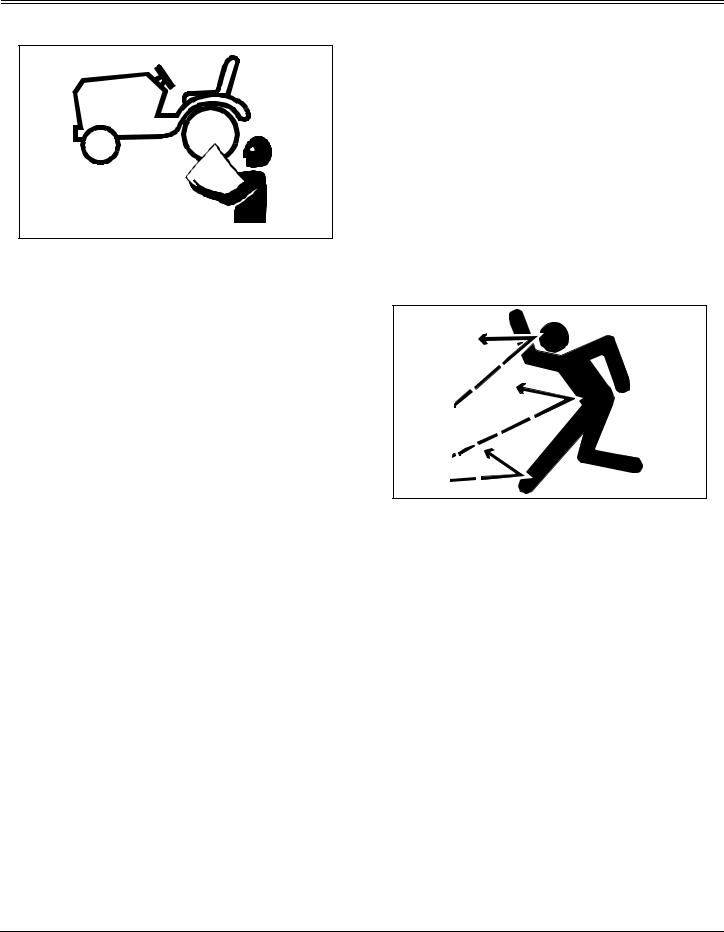
Rotating Blades are Dangerous
HELP PREVENT SERIOUS OR FATAL ACCIDENTS:
trees, or other objects that may block your vision.
•Do not let children or an untrained person operate the machine.
•Do not carry or let children ride on any attachment or machine even with the blades off. Do not tow children in a cart or trailer.
Avoid Tipping
•Rotating blades can cut off arms and legs.
•Keep hands, feet and clothing away from mower deck when engine is running.
•Be alert at all times, drive forward carefully. People, especially children can move quickly into the mowing area before you know it.
•Before backing up, shut off PTO and look down and behind the machine carefully, especially for children.
•Do not mow in reverse.
•Shut off blades when you are not mowing.
•Do not operate machine if you are under the influence of drugs or alcohol.
•Park machine safely before inspecting or unplugging mower or bagger.
PROTECT CHILDREN:
•Never assume that children will remain where you last saw them. Children are attracted to mowing activity, stay alert to the presence of children.
•Keep children indoors when you are mowing. Turn the machine off if a child enters the mowing area.
•Use extra care when you come to blind corners, shrubs,
•Slopes are a major factor related to loss-of-control and tip-over accidents, which can result in severe injury or death. If you cannot back up the slope or if you feel uneasy on it, do not mow it.
•Do not drive where machine could slip or tip.
•Stay alert for holes and other hidden hazards in the terrain.
•Keep away from drop-offs, ditches and embankments.
•Slow down before you make a sharp turn or operate on a slope. Choose a low gear so that you will not have to stop or shift while on the slope.
•Limit loads to those you can safely control. Use only approved hitches when pulling loads or using heavy equipment. Use counterweights or wheel weights as required in this manual or your attachment manual.
•Use wheel weights for added stability when operating on slopes or using rear mounted attachments.
•Drive up and down a hill - not across. Turn slowly and turn downhill. Do not shift to neutral and coast downhill.
•Do not stop when going up hill or down hill. If machine stops going up hill, disengage mower blades and back down slowly.
•Mowing when grass is wet can cause reduced traction and sliding.
•Do not try to stabilize the machine by putting your foot on the ground.
Safety - 4
SAFETY
Keep Riders Off |
Driving Safely on Public Roads |
•Only allow the operator on the machine. Keep riders off.
•Riders on the machine or attachment may be struck by foreign objects or thrown off the machine causing serious injury.
•Riders obstruct the operator’s view resulting in the machine being operated in an unsafe manner.
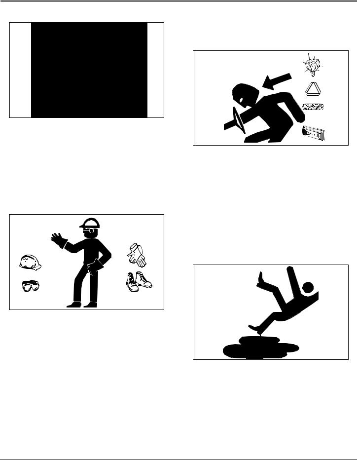
Wear Appropriate Clothing
•Wear close fitting clothing and safety equipment appropriate for the job.
•Always wear safety goggles or safety glasses with side shields when operating the mower.
•Wear a suitable protective device such as earplugs. Loud noise can cause impairment or loss of hearing.
•Do not wear radio or music headphones. Safe service and operation requires your full attention.
Avoid personal injury or death resulting from a collision with another vehicle on public roads:
•Use safety lights and devices. Slow moving machines when driven on public roads are hard to see, especially at night.
•Use extra care when loading or unloading the machine into a trailer or truck.
•Whenever driving on public roads, use flashing warning lights and turn signals according to local regulations. Extra flashing warning lights may need to be installed.
Practice Safe Maintenance
•Understand service procedure before doing work. Keep area clean and dry.
•Never lubricate, service, or adjust machine while it is moving. Keep safety devices in place and in working condition. Keep hardware tight.
•Keep hands, feet, clothing, jewelry, and long hair away from any moving parts, to prevent them from getting caught.
•Lower attachments to the ground before servicing
Safety - 5
SAFETY
machine. Disengage all power and stop the engine. Lock park brake and remove the key. Let machine cool.
•Disconnect battery or remove spark plug wire before making any repairs.
•Before servicing the machine, carefully release pressure from any components with stored energy, such as hydraulic components.
•Keep all nuts and bolts tightened, especially blade attachment bolts.
•Securely support any machine elements that must be raised for service work.
•Never run engine unless park brake is locked.
•Keep all parts in good condition and properly installed. Fix damage immediately. Replace worn or broken parts. Replace all worn or damaged safety and instruction decals.
•To prevent fires, remove any buildup of grease, oil, or debris from the machine, especially the engine compartment.
•Charge batteries in an open, well-ventilated area, away from sparks. Unplug battery charger before connecting or disconnecting from the battery. Use insulated tools.
•Do not modify machine or safety devices. Unauthorized modifications may impair its function and safety.
•Do not wear radio or music headphones while servicing the machine. Safe service requires your full attention.
Prevent Fires
•Never remove fuel cap, or add fuel with engine running or hot. Allow engine to cool for several minutes.
•Never store equipment with fuel in the tank inside a building where fumes may reach an open flame or spark.
•Allow engine to cool before storing in any enclosure.
•To reduce fire hazard, keep engine free of grass, leaves, or excessive grease.
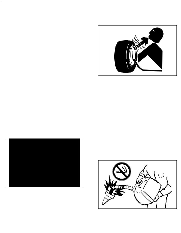
Tire Safety
Explosive separation of a tire and rim parts can cause serious injury or death:
•Do not attempt to mount a tire without the proper equipment and experience to perform the job.
•Always maintain the correct tire pressure. Do not inflate the tires above the recommended pressure. Never weld or heat a wheel and tire assembly. The heat can cause an increase in air pressure resulting in a tire explosion. Welding can structurally weaken or deform the wheel.
•When inflating tires, use a clip-on chuck and extension hose long enough to allow you to stand to one side and NOT in front of or over the tire assembly.
•Check tires for low pressure, cuts, bubbles, damaged rims or missing lug bolts and nuts.
Handling Fuel Safely
Fuel and fuel vapors are highly flammable:
•Do not refuel machine while you smoke, when machine is near an open flame or sparks, or when engine is running. stop engine and allow to cool before filling.
•Never remove the fuel cap or add fuel with the engine
Safety - 6
SAFETY
running.
•Never fill fuel tank or drain fuel from a machine in an enclosed area. Fill fuel tank outdoors.
•Prevent fires. Clean up spilled fuel immediately.
•Do not store machine with fuel in tank in a building where fumes may reach an open flame or spark.
•Prevent fire and explosion caused by static electric discharge. Use only non-metal, portable fuel containers approved by the Underwriter’s Laboratory (U.L.) or the American Society for Testing & Materials (ASTM). If using a funnel, make sure it is plastic and has no screen or filter.
•Static electric discharge can ignite gasoline vapors in an ungrounded fuel container. Remove the fuel container from the bed of a vehicle or the trunk of a car and place on the ground away from the vehicle before filling. Keep nozzle in contact with container opening while filling.
•When practical, remove equipment from trailers or truck beds and refuel them on the ground. If this is not possible, use a portable, plastic fuel container to refuel equipment on a truck bed or trailer.
•For gasoline engines, do not use gas with methanol. Methanol is harmful to your health and to the environment.
Handling Waste Product and Chemicals
Waste products, such as, used oil, fuel, coolant, brake fluid, and batteries, can harm the environment and people:
•DO NOT use beverage containers for waste fluids - someone may drink from them.
•See your local Recycling Center or John Deere dealer to learn how to recycle or get rid of waste products.
•A Material Safety Data Sheet (MSDS) provides specific details on chemical products: physical and health hazards, safety procedures, and emergency response techniques. The seller of the chemical products used with your machine is responsible for providing the MSDS for that product.
Safety - 7
OPERATING
Daily Operating Checklist
Test safety systems.
Check tire pressure.
Check fuel level.
Check engine oil level.
Remove grass and debris from machine.
Clean air intake screen.
Check area below machine for leaks.
Avoid Damage to Plastic and Painted Surfaces
•Do not wipe plastic parts unless rinsed first.
•Insect repellent spray may damage plastic and painted surfaces. Do not spray insect repellent near machine.
•Be careful not to spill fuel on machine. Fuel may damage surface. Wipe up spilled fuel immediately.
Operator Station Controls
A |
M |
B |
|
|
L |
C |
|
|
K |
D |
J |
|
|
E |
I |
|
|
|
H |
|
F |
G |
|
A- Choke Knob (V-Twin)
B- Throttle/Choke Control
C- Foot Pedal - Brake/Clutch/Return to Neutral
D- Reverse Implement Option Switch
E- Attachment Lift Lever
F- Locking Lever
G- Free Wheeling Knob (Automatic Models)
H- Hand Lever: Transmission Shift Lever (Hand Control Units) (or) Cruise Control Lever (Foot Control Units)
I- Park Brake
J- Foot Pedal, Reverse (Foot Control Units)
K- Foot Pedal, Forward (Foot Control Units)
L- PTO Drive Lever
M- Ignition Switch
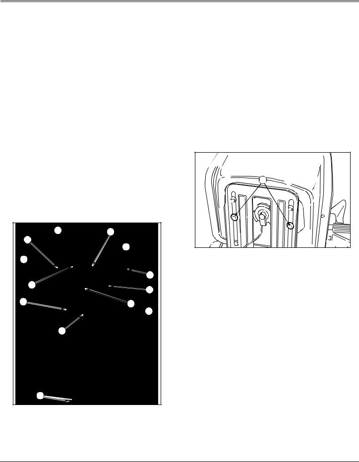
Adjusting Seat
1. Tip seat forward.
A |
M96454 |
Picture Note: Model with capscrew adjuster used for illustration.
2.Loosen two cap screws (A) two turns.
3.Slide seat forward or rearward on mounting bracket to desired position.
4.Tighten cap screws or knobs.
5.Lower seat.
Operating - 8
OPERATING
Adjusting Cutting Height
Cutting height can be adjusted from approximately 38 – 100 mm (1-1/2 – 4 in).
 A
A 
 B
B 
1.Push down on lift lever (A) slightly and hold locking lever (B) down with thumb.
2.Move lift lever to desired cutting height.
3.Release locking lever to keep lift lever in position.
4.Adjust gage wheels.
Adjusting Mower Deck Wheels
CAUTION: Avoid injury! Rotating blades are dangerous. Before adjusting or servicing mower:
•Disconnect spark plug wire(s) to prevent engine from starting accidently.
•Always wear gloves when handling mower blades or working near blades.
IMPORTANT: Avoid damage! The mower deck can be damaged if mower wheels are adjusted wrong:
•Wheels must not ride on ground supporting mower weight.
•Check wheel adjustment each time cutting height is changed.
1.Park machine safely. (See Parking Safely in the Safety Section.)
2.Inflate tires to the correct pressure.
3.Raise lift lever to transport position and adjust cutting height.
4.Move lift lever to mowing position.
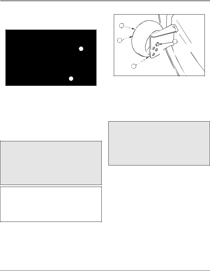
NOTE: Bottom of wheels should be approximately 6-13 mm (1/4-1/2 in.) from the ground.
D |
|
C |
A |
|
|
|
B |
5.Check mower wheel position. Remove bolt (A), bushing (B), washer (C), and nut (D) and move mower wheels to proper hole.
6.Install bolt and tighten with nut to lock wheels in position.
Adjusting Mower Level (Side-to-Side)
CAUTION: Avoid injury! Rotating blades are dangerous. Before adjusting or servicing mower:
•Disconnect spark plug wire(s) to prevent engine from starting accidently.
•Always wear gloves when handling mower blades or working near blades.
NOTE: Mower wheels should not contact the ground when leveling the deck.
1.Park machine safely on a level surface. (See Parking Safely in the Safety Section).
2.Inflate tires to the correct pressure.
3.Adjust cutting height to middle position.
4.Put lift lever in mowing position.
Operating - 9
OPERATING
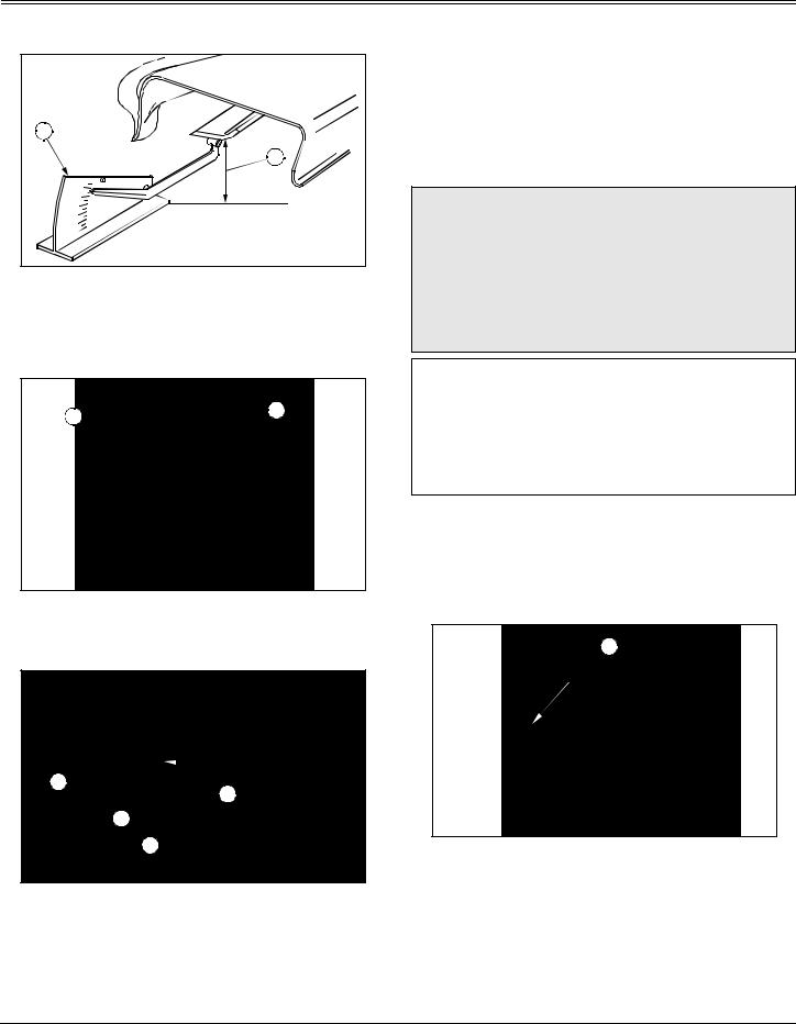
NOTE: The difference between blade measurements must not be more than 3 mm (1/8 in).
A |
B |
Picture Note: A convenient leveling gauge (A) is available from your Authorized Service Center.
5. Position mower blades as follows and measure from each outside blade tip (B) to the level surface.
 C
C 
 D
D 
• Turn left blade (C) as shown. Hold drive belt and turn right blade (D) as shown. Take measurement for both blades.
 E
E


 F
F 
 G
G
 H
H 
6.Loosen top clamping nut (E) facing inside of mower, on left hand side J-bolt (F), approximately one turn.
7.Loosen upper adjusting nut (G).
8.Adjust lift links by turning lower adjusting nut (H) clockwise to raise left side of mower, counterclockwise to
lower left side of mower.
9. Tighten upper adjusting nut.
10.Tighten clamping nut.
11.Measure blade tips again and adjust if necessary.
Adjusting Mower Level (Front-to-Rear)
CAUTION: Avoid injury! Rotating blades are dangerous. Before adjusting or servicing mower:
•Disconnect spark plug wire(s) to prevent engine from starting accidently.
•Always wear gloves when handling mower blades or working near blades.
IMPORTANT: Avoid damage! Make sure each front draft rod is equally tensioned. The installed rods should exhibit identical amounts of movement between left and right rods. If one rod moves more freely than the other, the adjustment nut should be tightened until the movement of the assembly matches that of the other side.
1.Park machine safely on a level surface. (See Parking Safely in the Safety Section).
2.Inflate tires to the correct pressure.
3.Adjust cutting height to middle position.
4.Put lift lever in mowing position.
 A
A 
5.Turn blades so front blade tips (A) point straight forward.
6.Measure from each blade tip to the surface.
• The front blade tip must be 6–9 mm (1/4–3/8 in.) lower than rear blade tip.
Operating - 10

OPERATING
 C
C 
 C
C 
 B
B 
 B
B 
7.Turn nuts (B) on front draft rods (C) equally until adjustment is correct. Turn nut clockwise to raise front of mower deck or counterclockwise to lower front of mower deck.
8.Measure blade tips again and adjust if necessary.
Testing Safety Systems
CAUTION: Avoid injury! Engine exhaust fumes contain carbon monoxide and can cause serious illness or death.
Move the vehicle to an outside area before running the engine.
Do not run an engine in an enclosed area without adequate ventilation.
•Connect a pipe extension to the engine exhaust pipe to direct the exhaust fumes out of the area.
•Allow fresh outside air into the work area to clear the exhaust fumes out.
Use the following checkout procedure to check for normal operation of machine.
If there is a malfunction during one of these procedures, Do not operate machine. See your John Deere dealer for
service.
Perform these tests in a clear open area. Keep bystanders away.
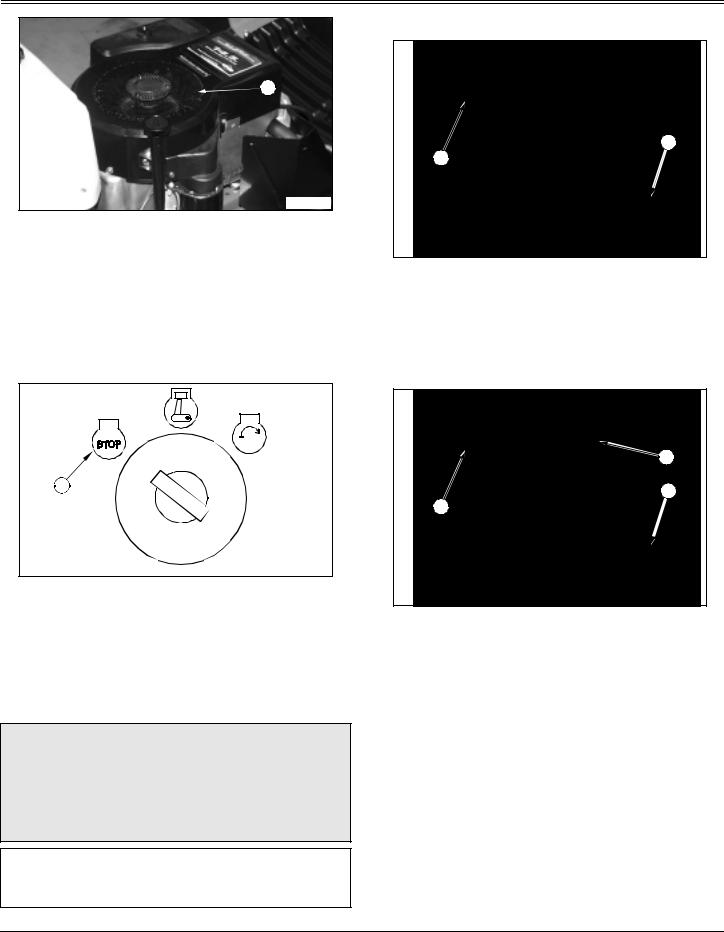
Testing Mower Engagement Lever Switch
1.Sit on the seat.
2.Lock the park brake.
3.Push mower engagement lever (A) forward to engage.
4.Try to start engine.
Result: Engine must not start. If engine starts, there is a problem with your safety interlock circuit.
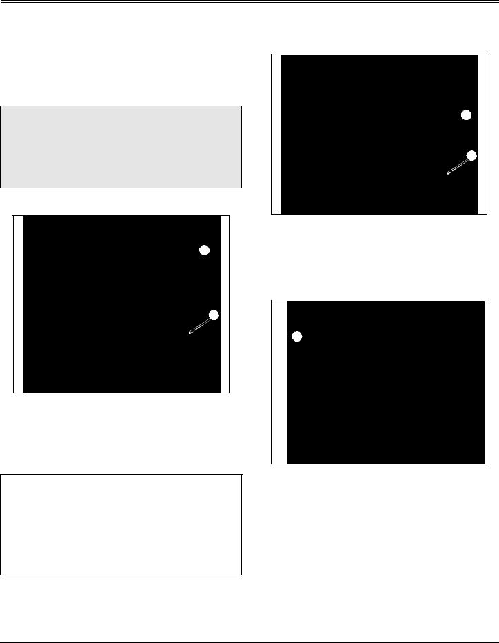
Testing Seat Switch
First Test:
1.Sit on seat.
2.Lock the park brake.
 A
A 
 B
B 
3.Pull mower engagement lever (A) back to disengage.
4.Start engine and move throttle lever (B) to half-speed ( ) position.
5.Push mower engagement lever (A) forward to engage.
6.Move throttle lever to fast ( ) speed position.
7.Raise up off of seat, but do not get off tractor.
Result: Engine will begin to stop. If engine does not begin to stop, there is a problem with your safety interlock circuit.
Second Test:
1.Sit on seat.
2.Lock the park brake.
Operating - 11

OPERATING
 A
A 
 B
B 
3.Pull mower engagement lever (A) back to disengage.
4.Start engine and move throttle lever (B) to fast ( ) speed position.
5.Raise up off of seat, but do not get off tractor.
Result: Engine should continue to run. If engine stops, there is a problem with your safety interlock circuit.
Testing Park Brake Switch
1.Sit on seat.
2.Unlock the park brake.
3.Pull mower engagement lever (A) back to disengage.
4.Try to start engine.
Result: Engine must not start. If engine starts, there is a problem with your safety interlock circuit.
Testing Park Brake
1.Shut the engine off and lock the park brake (A).
2.Put transmission in N (neutral).
3.Try to push machine manually. Use free-wheeling lever on units with an automatic transmission.
Result: Park brake must prevent machine from moving. If machine moves, parking brake needs to be adjusted.
Testing Reverse Implement Option (RIO)
1.Start engine.
2.Engage mower.
CAUTION: Avoid injury! Rotating blades are dangerous. Children or bystanders may be injured by runover and rotating blades.
Before backing up, carefully check the area around the machine.
3.Look behind the vehicle to be sure there are no bystanders.
4.Begin reverse travel by depressing reverse foot pedal for Automatic transmission or moving gear shift lever to R (reverse) position for Gear transmission.
Result: Mower and engine should stop operation. If mower or engine continues to operate as tractor begins travel in reverse, do not continue to operate mower.
Using Park Brake
Locking park brake:
 A
A 
 B
B 
1.Push and hold brake pedal (A) down.
2.Move park brake lever (B) forward, then to the left to lock position.
3.Release brake pedal. Pedal should stay down and park brake lever should stay locked.
Unlocking park brake:
1.Push and hold brake pedal down.
2.Move park brake lever to the right, then to the rear.
3.Release brake pedal.
Operating - 12
OPERATING
Starting Engine
CAUTION: Avoid injury! Engine exhaust fumes contain carbon monoxide and can cause serious illness or death.
Move the vehicle to an outside area before running the engine.
DO NOT run an engine in an enclosed area without adequate ventilation.
•Connect a pipe extension to the engine exhaust pipe to direct the exhaust fumes out of the area.
•Allow fresh outside air into the work area to clear the exhaust fumes out.
NOTE: Engine will not start unless mower is disengaged and transmission is in neutral.
1.Disengage mower blades.
2.Lock the park brake.
3.Put transmission in neutral.
4.Check starting conditions:
 B
B 
 A
A 
Picture Note: Model 2046
•If engine is cold:
On Model 2046, move throttle lever (A) to the half-speed ( ) position and pull out choke ( ) knob (B). Gradually push in the choke knob after the engine starts and warms up.
On all other Models, move throttle lever (A) to the choke ( ) position.
•If engine is warm:
On Model 2046, pull out choke ( ) knob (B). Push choke knob in as soon as the engine starts.
On all other Models, move throttle lever (A) to the halfspeed ( ) position.
IMPORTANT: Avoid damage! Starter may be damaged if starter is operated for more than 20 seconds at a time:
• Wait two minutes before trying again if engine does not start.
D |
C |
5.Turn key to start position (C) for no longer than five seconds.
6.Release key to run position (D) when engine starts.
•If engine does not start, wait 10 seconds.
•Turn key to start position again for no longer than 5 seconds.
•Repeat procedure if necessary.
IMPORTANT: Avoid damage! Unnecessary engine idling may cause engine damage. Excessive idling can cause engine overheating, carbon build-up, and poor performance.
7. Let engine run at half-speed ( ) position for a couple of minutes to warm-up before operating machine.
Idling Engine
IMPORTANT: Avoid damage! Unnecessary engine idling may cause engine damage. Excessive idling can cause engine overheating, carbon build-up, and poor performance.
Operating - 13
OPERATING
 A
A 
M96455
Engine is air cooled and needs a large volume of air to keep cool. Keep air intake screen (A) on top of engine clean.
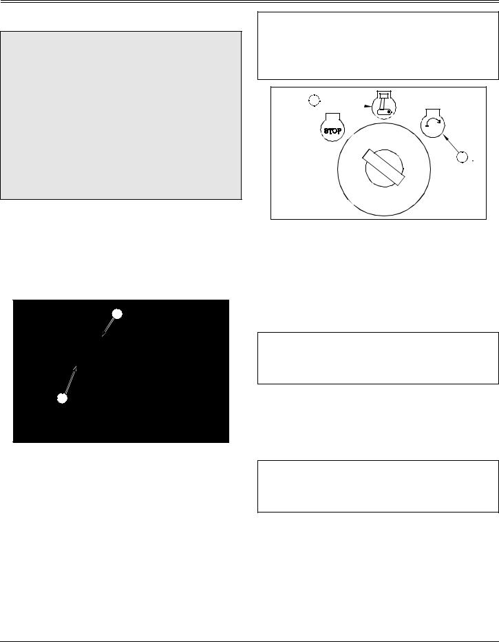
Stopping Engine
1. Move throttle lever (A) to slow ( ) position. Let engine run at low throttle a few seconds.
 B
B
2.Turn key to stop position (B).
3.Lock the park brake.
4.Remove key.
Using Travel Controls on Gear Transmission
CAUTION: Avoid injury! Children or bystanders may be injured by runover and rotating blades. Before traveling forward or rearward:
•Carefully check the area around the machine.
•Disengage the mower before backing up.
IMPORTANT: Avoid damage! Stop machine movement before shifting between reverse and forward to prevent transmission damage.
To travel forward:
 B
B 
 A
A 
1.Push clutch/brake pedal (A) all the way down to stop machine.
2.Move shift lever (B) to desired travel speed.
3.Release clutch/brake pedal slowly.
To travel in reverse:
 C
C 
 B
B 
 A
A 
1. Push clutch/brake pedal (A) all the way down.
NOTE: The engine and mower will stop as the gear shift lever is moved to R (reverse) if the mower engagement lever is not in the off position.
2.Put mower engagement lever (C) in the off position.
3.Look behind the vehicle to be sure there are no bystanders nearby.
4.Move shift lever (B) to R (reverse) position.
5.Release clutch/brake pedal slowly.
Operating - 14
OPERATING
To stop travel: |
1. |
Put mower engagement lever in the off position. |
Push down clutch/brake pedal. |
2. |
Look behind the vehicle to be sure there are no |
|
bystanders nearby. |
|
Using Travel Controls on Automatic
Transmission
CAUTION: Avoid injury! Children or bystanders  C may be injured by runover and rotating blades.
Before traveling forward or rearward:
 A
A 
• Carefully check the area around the machine.
• Disengage the mower before backing up.
To travel forward:
 B
B 
 A
A 
•Units with shift lever: Move transmission shift lever (A) to the right and forward to desired speed.
•Units with foot control: Push down the forward travel pedal (B).
To travel in reverse:
IMPORTANT: Avoid damage! To prevent transmission damage, stop tractor movement before changing direction of travel.
When cruise control is not in use, hand lever should be returned manually, all the way rearward to OFF position. Otherwise, hand lever will restrict travel of reverse pedal linkage and reverse speed of tractor will be too slow.
NOTE: The engine and mower will stop as the shift lever is moved to R (reverse) or the reverse pedal is pushed if the mower engagement lever is not in the off position.
3. Units with shift lever: Move transmission shift lever (A) reward into the R (reverse) position.
Units with foot control: Push down the reverse travel pedal
(C).
To stop travel:
 D
D 
•Units with shift lever: Push down on brake/clutch pedal
(D). Transmission shift lever will automatically return to NEUTRAL position and brakes will be applied.
•Units with foot control: If cruise control is engaged, move lever to off position. Release travel pedals and unit will automatically return to neutral and stop. Push down on brake/clutch pedal (D). Brakes will be applied to assist in stopping.
Operating - 15

OPERATING
Using Cruise Control
CAUTION: Avoid injury! DO NOT use cruise control when going down hills. Tractor speed will increase. Operate tractor in a large, open area to learn how the cruise control works
IMPORTANT: Avoid damage! When cruise control is not in use, hand lever should be returned manually, all the way rearward to OFF position. Otherwise, hand lever will restrict travel of reverse pedal linkage and reverse speed of tractor will be too slow.
Use cruise control when you want to maintain travel speed without having to hold the forward travel pedal down. Cruise control operates only for forward travel.
Engage cruise control:
 A
A 
1.Put the cruise control lever (A) in the off position.
2.Move cruise control lever forward.
•Move cruise control lever toward the ( ) position to begin forward travel.
•Increase tractor speed by moving the cruise control lever toward the ( ) position.
•Select desired speed and release lever.
Disengage cruise control:
1. Depress brake pedal or put cruise control lever in the off position
Using The Reverse Implement Option (RIO)
CAUTION: Avoid injury! Rotating blades are dangerous. Children or bystanders may be injured by runover and rotating blades.
Before backing up, carefully check the area around the machine.
NOTE: Backing up while the mower is engaged is strongly discouraged. The Reverse Implement Option should be used ONLY when operating another attachment or when the operator deems it necessary to reposition the machine with the mower engaged.
1.Stop forward travel.
2.Look behind the vehicle to be sure there are no bystanders.
3.Push and hold in the reverse implement switch (A) while depressing reverse foot pedal slightly for Automatic Transmission OR moving the gear shift lever to the R (reverse) position for Gear Transmission.
NOTE: If the engine and mower stop while repositioning the machine, return the mower engagement lever to the off position. Start engine and engage mower. Begin again with Step 2.
4.Release the reverse implement switch and reposition the machine as the machine begins to move rearward.
5.Resume forward travel. The mower should continue operating.
6.Repeat procedure to position the machine again.
Using Mower Lift Lever
 A
A 
 B
B 
1.Push down on lift lever (A) slightly and hold locking lever
(B) down with thumb.
2.Move lift lever (A) down to lower mower or up to raise mower.
Operating - 16
OPERATING
3. Release locking lever lock (B) to keep lift lever (A) in position.
Using Mower
1.Start engine and allow it to idle for two to three minutes.
2.Lower mower to cutting height.
 A
A 
 B
B 
3.Push throttle lever (A) up to the full throttle ( ) position.
4.Push mower engagement lever (B) forward to start mower.
5.Pull lever (B) back to stop mower blades.
Mower Blade Selection
•Standard Blades: Designed for bagging, side discharging, and all mowing conditions.
•Bagging Blades: Designed for cutting and bagging thick, tall grass and/or leaves.
IMPORTANT: Avoid damage! Blades that are not specifically used for mulching, will destroy the mulch plug and may damage the tractor and mower deck. Mulching blades must be used with the mulch plug insert.
• Mulching Blades: Must be used only with the Mulch Plug. See your John Deere dealer.
Using Mower Deck Side Discharge (42-Inch
Mower Deck)
CAUTION: Avoid injury! Before you adjust mower: STOP engine, remove key, and wait for blades to STOP.
Be careful, sharp edges on mower blades. Always wear gloves when handling mower blades.
NOTE: For maximum side discharge operation, it may be necessary to change the mower blades, see Servicing Mower Blades in the SERVICE MOWER section.
 B
B 
 B
B 
 A
A 
M96105
To set-up and operate the 42” deck for side discharge operation the factory installed mulch cover (A) must be removed.
1.Remove mulch cover:
•Lift plastic discharge chute.
•Grasp corner of steel chute, pull outward to unlock and pivot up.
•Unhook both rubber hooks (B) and remove mulch cover.
2.Store mulch cover in a well protected area and have it readily available for when you want to use deck as a mulching deck.
Operating - 17
Loading...