


John Deere RT 1307 WR, RT 1308 WR, RT 1370, RT 1310, RT 1310 WR User Manual
...O P E R A T O R ’ S M A N U A L
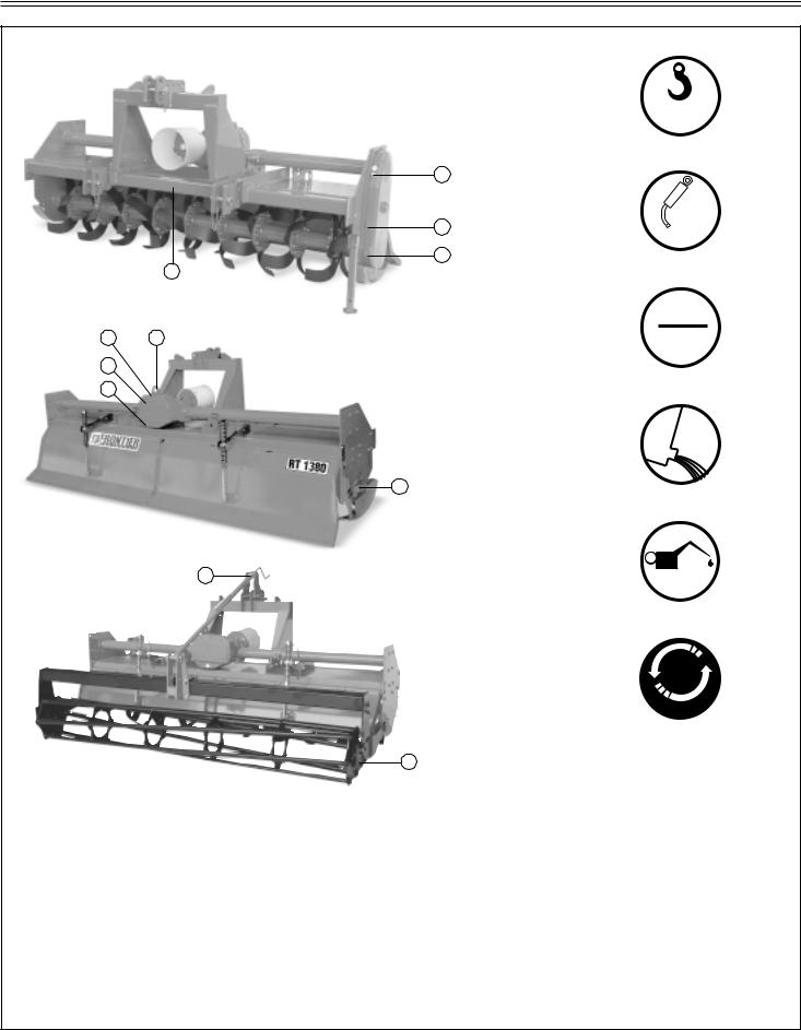
ROTARY TILLERS
RT 1370
RT 1370 WR
RT 1380
RT 1380 WR
RT 1307
RT 1307 WR
RT 1308
RT 1308 WR
RT 1310
RT 1310 WR
Cod. F07010184 / Rev. 01 (2006-01)

TABLE OF CONTENTS
Technical specification |
|
Change speed.............................................. |
15 |
Technical specification ................................. |
4 |
Tilling tips ..................................................... |
16 |
Technical specification - Hitch ...................... |
4 |
During tilling ................................................. |
16 |
|
|
Replacement parts ....................................... |
16 |
Safety signs |
|
Safety-Alert simbol ....................................... |
5 |
Identification machine .................................. |
5 |
Machine safety labels .................................. |
5 |
Service Machine Safely |
|
Practice safe maintenance........................... |
17 |
Wear appropriate clothing ............................ |
17 |
Stay clear of rotating drivelines .................... |
17 |
Machine safety labels and positions |
|
Machine safety labels and positions ............ |
6 |
Preparing the vehicle |
|
Preparing the tractor .................................... |
8 |
Park vehicle safety ....................................... |
8 |
Stay clear of rotating drivelines .................... |
8 |
Installing |
|
Quick Coupler .............................................. |
8 |
PTO shaft ..................................................... |
9 |
PTO shaft with clutch ................................... |
10 |
Park vehicle safely ....................................... |
10 |
Stay clear of rotating drivelines .................... |
10 |
Removing |
|
Removing tiller with Quick Coupler .............. |
11 |
Operating |
|
Operate safely.............................................. |
12 |
Wear appropriate clothing ............................ |
13 |
Stay clear of rotating driveline...................... |
13 |
Raising parking stand .................................. |
13 |
Lowering parking stand ................................ |
13 |
Levelling attachments (side-to-side) ............ |
13 |
Levelling tiller (front-to-rear) ......................... |
14 |
Adjusting skid shoes (only skid version) ...... |
14 |
Adjusting roller ............................................. |
14 |
Adjusting leveling board ............................... |
15 |
Service lubrication |
|
Service lubrication........................................ |
18 |
Every 8 work hours ...................................... |
18 |
Every 50 work hours .................................... |
18 |
Every 400 work hours .................................. |
18 |
Greasing and lubricant points ...................... |
19 |
Lubricants .................................................... |
19 |
Bolts tighteening torques ............................. |
19 |
Service |
|
Replacing tines ............................................ |
20 |
Tines ............................................................ |
20 |
Troubleshooting |
|
Using troubleshooting chart ......................... |
21 |
Storing machine |
|
Storing tiller .................................................. |
22 |
Removing tiller from storage ........................ |
22 |
Assembly / Spare parts |
|
Assembly ..................................................... |
23 |
Installing driveline on tiller ............................ |
26 |
Spare parts .................................................. |
26 |
Warranty |
|
Warranty ...................................................... |
27 |
Warranty for replacement parts ................... |
28 |

TO THE DEALER:
Assembly and proper installation of this product is the responsibility of the Frontier dealer. Read manual instruction and safety rules. Make sure all items on the Dealer’s Pre-Delivery Check List in the Operator’s Manual are completed before releasing equipment to the owner.
The dealer must complete the Warranty Registration, located on the Frontier website. Warranty claims will be denied if the Warranty Registration has not been completed.
TO THE OWNER:
Read this manual before operating your frontier equipment. The information presented will prepare you to do a better and a safer job. Keep this manual handy for ready reference. Require all operators to read this manual carefully and become acquainted with all the adjustment and operating procedures before attempting to operate. Replacement manuals can be obtained from your selling dealer.
The equipment you have purchased has been carefully enginereed and manufactured to provide dependable and satisfactory use. Like all mechanical products, it will require cleaning and upkeep. Lubricate the unit as specified. Observe all safety information in this manual and safety decals on the equipment.
For service, your authorized Frontier dealer has trained mechanics, genuine Frontier service parts, and the necessary tools and equipment to handle all your needs.
Use only genuine Frontier service parts.Substitute parts will void the warranty and may not meet standards required for safe and satisfactory operation. Record the model number and serial number of your equipment in the spaces provided:
Model: |
|
Date of Purchase |
Serial Number: (see Safety Decal section for location)
Provide this information to your dealer to obtain correct repair parts.
Throghout this manual, the term IMPORTANT is used to indicate that failure to observe can cause damage to equipment. The terms CAUTION, WARNING and DANGER are used in conjunction with the Safety-Alert Symbol, (a triangle with an esclamation mark), to indicate the degree of hazard for items of personal safety.
DANGER
 WARNING
This Safety-Alert Simbol indicates a hazard and means ATTENTION! BECOME ALERT! YOUR SAFETY IS INVOLVED!
Indicates an imminently hazardous situation that, if not avoided, will result in death or serious injury.
Indicates a potentially hazardous situation that, if not avoided, could result in death or serious injury, and includes hazards that are exposed when guards are removed.
CAUTION |
Indicates a potentially hazardous situation that, if not avoided, may |
|
result in minor or moderate injury. |
IMPORTANT |
Indicates that a failure to observe can cause damage to equipment. |
NOTE |
Indicates helpful information. |
Cod. F07010184 / Rev. 01 (2006-01)
TECHNICAL SPECIFICATIONS
|
|
|
|
|
|
SKID VERSION |
|
|
|
|
||
|
|
|
|
|
|
ROLLER VERSION |
|
|
|
|
||
|
|
|
|
|
|
|
|
|
|
|
|
|
Model |
Work/width |
Tractor HP |
Tractor HP |
Weight |
Side |
PTO |
Speeds |
Input |
Hitch |
Tines |
Rotor |
Rotor |
|
inches |
min |
max |
lbs. |
Drive |
shaft |
gear box |
speed |
|
STD |
blades |
flanges |
|
|
|
|
|
|
|
|
|
Cat. “II” |
|
|
|
RT 1370 |
72 |
50 |
130 |
1373 |
Gear |
Slip |
2 + 2 |
540 |
Quick |
L |
6 |
8 |
RT 1370 WR |
72 |
50 |
130 |
1628 |
|
Clutch |
Speed |
|
coupler |
|
|
|
|
|
|
|
|
|
|
|
|
|
|
|
|
|
|
|
|
|
|
|
|
|
Cat. “II” |
|
|
|
RT 1380 |
82 |
60 |
130 |
1487 |
Gear |
Slip |
2 + 2 |
540 |
Quick |
L |
6 |
9 |
RT 1380 WR |
82 |
60 |
130 |
1760 |
|
Clutch |
Speed |
|
coupler |
|
|
|
|
|
|
|
|
|
|
|
|
|
|
|
|
|
|
|
|
|
|
|
|
|
Cat. “II” |
|
|
|
RT 1307 |
91 |
70 |
130 |
1602 |
Gear |
Slip |
2 + 2 |
540 |
Quick |
L |
6 |
10 |
RT 1307 WR |
91 |
70 |
130 |
1878 |
|
Clutch |
Speed |
|
coupler |
|
|
|
|
|
|
|
|
|
|
|
|
|
|
|
|
|
|
|
|
|
|
|
|
|
Cat. “II” |
|
|
|
RT 1308 |
101 |
80 |
130 |
1707 |
Gear |
Slip |
2 + 2 |
540 |
Quick |
L |
6 |
11 |
RT 1308 WR |
101 |
80 |
130 |
2002 |
|
Clutch |
Speed |
|
coupler |
|
|
|
|
|
|
|
|
|
|
|
|
|
|
|
|
|
|
|
|
|
|
|
|
|
Cat. “II” |
|
|
|
RT 1310 |
121 |
100 |
130 |
1918 |
Gear |
Slip |
2 + 2 |
540 |
Quick |
L |
6 |
13 |
RT 1310 WR |
121 |
100 |
130 |
2244 |
|
Clutch |
Speed |
|
coupler |
|
|
|
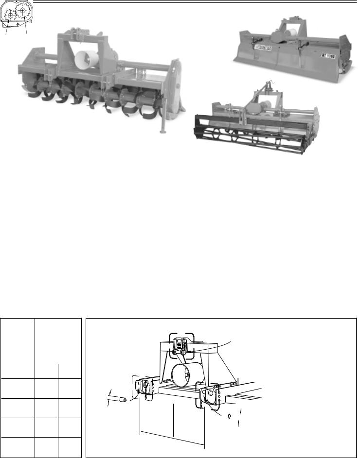
TECHNICAL SPECIFICATIONS - HITCH
rpm |
RT: Cat. «II» Quick Coupler |
rpm |
|
|
|
|
|
|
540 |
A |
B |
|
|
|
|
175 |
21 |
19 |
|
|
|
|
|
|
|
Ø |
|
|
|
214 |
19 |
21 |
|
|
|
|
262 |
17 |
23 |
|
= |
|
|
|
|
|
mm |
= |
||
|
|
|
823 |
|||
|
|
|
|
- |
|
|
|
|
|
|
|
inch |
|
143 |
23 |
17 |
|
|
32,4 |
cat. |
|
|
|
|
|
|
2 |
Cat. II Quick Coupler pin Ø mm 32 (inch 1.26)

 Ø
Ø
Cat. «II» Quick Coupler bushings Ø = 36,5 (inch 1.44)
Technical specifications - Page 4

SAFETY SIGNS
Safety-alert symbol
Read and recognize safety information.
Be alert to the potential for personal injury when you see this safety-alert symbol.
On your machine safety labels, the words DANGER, WARNING, and CAUTION are used with safetyalert symbol.
DANGER identifies the most serious hazards. In this manual, the word CAUTION and this symbol call attention to safety messages.
Identification machine
Identification plate machine
Machine safety labels
1) WARNING: AVOID INJURY FROM ROTATING KNIVES:
• Keep hands, feet and clothing away.
2) WARNING: AVOID INJURY FROM PTO:
•Keep all shields in place. Keep hands, feet and clothing away.
•Operate only with 540 RPM.
3)CAUTION: AVOID INJURY
•Read Operator’s Manual
•Ballast power unit per operator’s manual
•Know location and function of controls
•Keep all shields in place
•Stay clear of power driven parts
•Never carry riders
•Keep people and pets a safe distance away from machine
BEFORE DISMOUNTING OR SERVICING
•Shut off engine and remove key
•Lock brake for park
•Lower or block up machine
4)DANGER: ROTATING DRIVELINE - CONTACT CAN CAUSE DEATH - KEEP AWAY! - DO NOT OPERATE WITHOUT:
•All driveline, tractor and equipment shields in place
•Drivelines securely attached at both ends
•Drivelines shields that turn freely on driveline.
5)DANGER: SHIELD MISSING DO NOT OPERATE
Picture Note: Separate telescoping driveshaft members to locate safety label. Label attached to outer profile tube.
Safety Signs - Page 5

MACHINE SAFETY LABELS AND POSITIONS
2
3
1
1
2
3
1
2 1
3
4
5
1
2
3
|
|
|
|
|
|
|
|
|
|
|
|
|
|
|
|
|
|
|
|
|
|
|
|
|
|
|
|
|
|
|
|
|
|
|
|
|
|
|
|
|
|
|
|
|
|
|
|
|
|
|
|
|
|
|
|
|
|
|
|
|
|
|
|
|
|
|
|
|
|
|
|
|
|
|
|
|
|
|
|
|
|
|
|
|
|
|
|
|
|
|
|
|
|
|
|
|
|
|
|
|
|
|
|
|
|
|
|
|
|
|
|
4 |
|
|
5 |
|
|
|
Safety Signs - Page 6
MACHINE SAFETY LABELS AND POSITIONS
MAX
Kg...
|
6 |
|
10 |
|
8 |
|
GREASE |
|
9 |
11 |
7 |
OIL
10 6
8
LEVEL
9 |
8 |
OIL
7
9
7 |
OIL |
10
540  MAX
MAX
11
7
6)Coupling point for lifting (indicating the maximun capacity)
7)Greasing point
8)Oil level plug
9)Oil drain plug
10)Oil fill plug
11)Number of revolutions of power takeoff
Safety Signs - Page 7
PREPARING THE VEHICLE
Preparing the tractor
CAUTION: Avoid injury. Proper ballastings is required for safe operation of your tiller
IMPORTANT: Refer to the tractor operator manual for proper ballasting information and tire inflation
•A 540 rpm PTO
•Refer to the tractor operator manual for correct ballasting and tire pressure, depending on installed equipment.
Park vehicle safety
•Stop vehicle on a lever surface, not on a slope.
•Disengage PTO.
• Engage the park brake. |
|
|
• |
STOP the engine. |
|
• |
Remove the key. |
|
• |
Before you leave the operator’s seat, wait for engine |
D |
|
and all moving parts to STOP. |
B |
Stay clear of rotating drivelines |
D |
|
|
||
Entanglement in rotating driveline can cause serious |
|
|
injury or death: |
A |
|
• Wear close fitting clothing. |
||
|
||
• STOP the engine and be sure PTO driveline is stopped |
C |
|
before getting near it. |
||
|
||
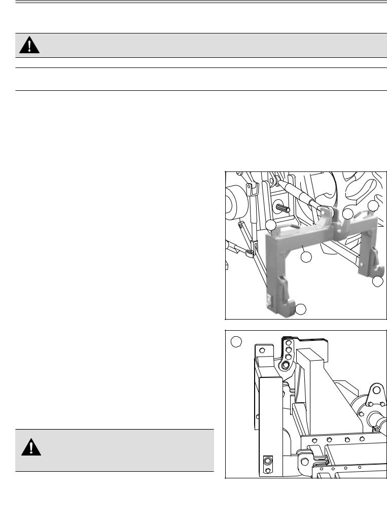
Quick Coupler |
C |
|
|
||
1) Install hitch Quick Coupler (A) on the tractor (see |
E |
|
tractor operator manual). |
||
|
||
2) Stop vehicle on a level surface, not on a slope, then |
|
|
moving back to the tractor until the Quick Coupler |
|
|
(A) is range with the (B) and (C) hitch points. |
|
|
3) Raise the Quick Coupler (A) and make sure that tiller’s |
|
|
hitch is in the right position (E). |
|
|
CAUTION: Before you work around hitch: |
|
|
• STOP engine. |
|
|
• LOCK park brake. |
|
|
• FIRMLY block tiller on horizontal surface. |
|
Preparing the vehicle - Page 8
INSTALLING
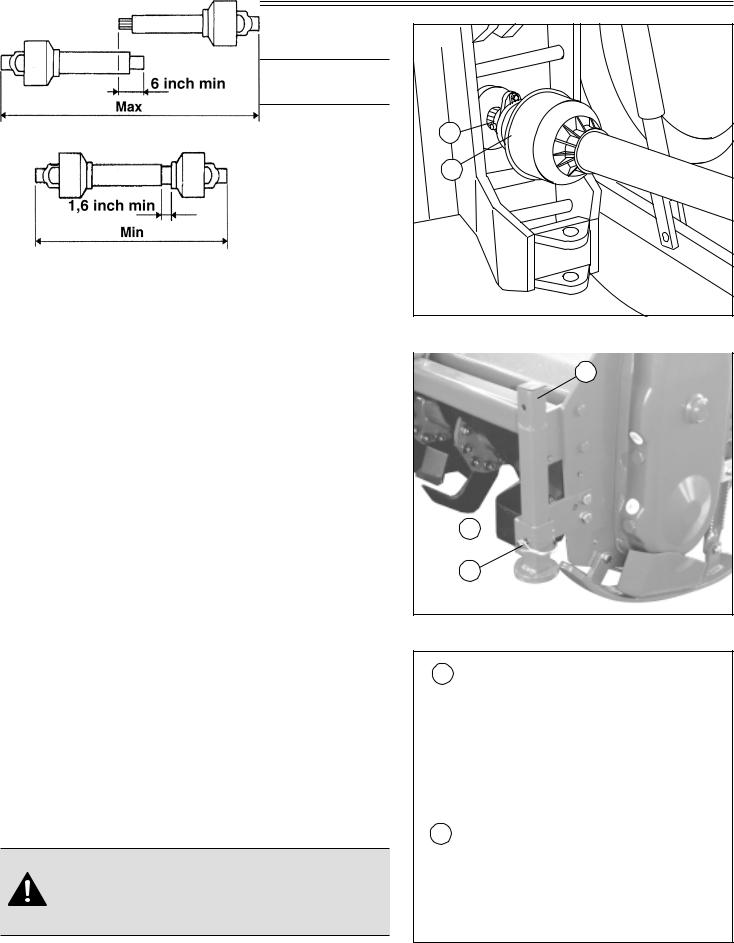
3. Install PTO shaft to tractor.
IMPORTANT: Tiller MUST BE level front to rear.
•Engage the cardan shaft and check that it is perfectly locked on the tractor PTO (G). Check that the guard
(H)is free to turn and fix it with the relative latch.
4.Raise tiller.
5.Remove spring locking pin (K) from parking stand.
6.Slide parking stand (I) and way up on tiller bracket
(J).
7.Fasten with spring locking pin (K).
8.Level tiller (See Leveling Tiller in the Operating Tiller section).
9.Adjust sway chains on tractor lower draft arms to minimize side way.
PTO shaft
The PTO shaft, supplied with the machine, is of standard length.
Therefore it might be necessary to adapt the PTO shaft.
In that case, before doing anything, consult the Manufacturer for the eventual adaptation.
When the PTO shaft is fully extended, the two tubes must overlap by at least 6 inch (A). When fully inserted, the minimum play must be 1,6 inch (B).
CAUTION: If the implement is used on another tractor, always check that the guards completely cover the rotating parts of the PTO shaft.
G |
H |
I |
J
K
Only skid version
A
B
Installing - Page 9
INSTALLING
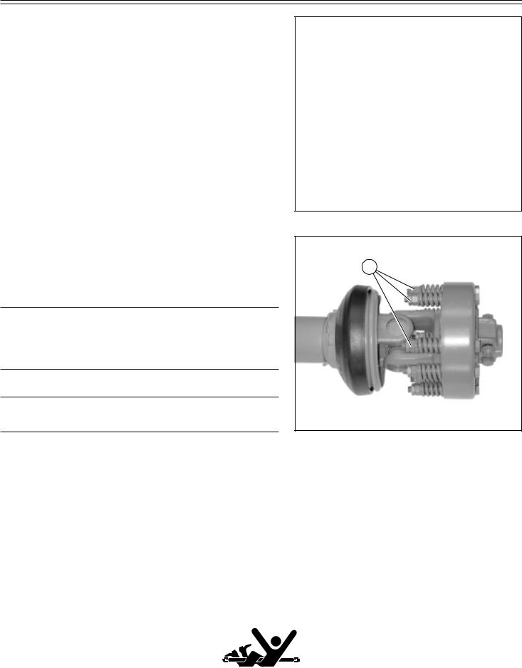
PTO shaft with clutch
The PTO shaft can be equipped with safety clutch to protect the transmission components of the machine from stress and/or excessive overloads.
The tilt of the PTO shaft must not exceed 10 degrees.
The clutch is already pre-adjusted for average stress. If it slips too easily (and overheats), it will be necessary to evenly tighten all the nuts (D) that retain the springs.
The clutch disks must be changed if the clutch still slips after all the nuts have been tightened.
If the clutch does not slip, evenly unscrew all the spring fixing nuts (D). Unscrew one turn at a time and check the clutch after having worked about 300 meters. Repeat the operation if necessary, remembering to unscrew one turn at a time. If the clutch maintains a temperature of about
40-50 (104-122 ° F) degrees during work, this means that it has been correctly regulated.
IMPORTANT: Never fully tighten the nuts. This would void the function of the springs and, subsequently, of the clutch, thus damaging the transmission components.
NOTE: This inspection must be performed at the beginning of each new season.
Park vehicle safely
D |
•Stop vehicle on a level surface, not on a slope.
•Disengage PTO.
•Engage the park brake.
•STOP the engine.
•Remove the key.
•Before you leave the operator’s seat, wait for engine and all moving parts to STOP.
Stay clear of rotating drivelines
Entanglement in rotating driveline can cause serious injury or death:
•Wear close fitting clothing.
•STOP the engine and be sure PTO driveline is stopped before getting near it.
Installing - Page 10
 Loading...