


 Loading...
POWERTECH
4.5 and 6.8 L
4045 and 6068 Tier 2 / Stage II OEM Diesel Engines
OPERATOR’S MANUAL
POWERTECH 4.5 and 6.8 L Tier 2 /
Stage II OEM Diesel Engines
OMRG33324 Issue 7Aug06 (ENGLISH)
CALIFORNIA
Proposition 65 Warning
Diesel engine exhaust and some of its constituents are known to the State of California to cause cancer, birth defects, and other reproductive harm.
If this product contains a gasoline engine:
 WARNING
The engine exhaust from this product contains chemicals known to the State of California to cause cancer, birth defects or other reproductive harm.
The State of California requires the above two warnings.
John Deere Power Systems
LITHO IN U.S.A.

Introduction
Foreword
THIS MANUAL CONTAINS INFORMATION to operate and service the following Tier 2 / Stage II emission-certified1 engines:
Saran-built (France) Tier 2 Mechanically Controlled
Engines:
•CD4045DF270
•CD4045TF270
Saran-built (France) Tier 2 Electronically Controlled
Engines:
•CD4045TF275 (DE10 Fuel System)
•CD4045HF275 (DE10 Fuel System)
•CD4045HF475 (HPCR System; 4-Valve Head)
•CD6068TF275 (DE10 Fuel System)
•CD6068HF275 (DE10/VP44 Fuel System)
•CD6068HF475 (HPCR System; 4-Valve Head)
Torreon-built (Mexico) Tier 2 Mechanically Controlled
Engines:
•PE4045DF270
•PE4045TF270
Torreon-built (Mexico) Tier 2 Electronically Controlled
Engines:
•PE4045TF275 (DE10 Fuel System)
•PE4045HF275 (DE10 Fuel System)
•PE4045HF475 (HPCR System; 4-Valve Head)
•PE6068TF275 (DE10 Fuel System)
•PE6068HF275 (DE10/VP44 Fuel System)
• PE6068HF475 (HPCR System; 4-Valve Head)
READ THIS MANUAL carefully to learn how to operate and service your engine correctly. Failure to do so could result in personal injury or equipment damage.
THIS MANUAL SHOULD BE CONSIDERED a permanent part of your engine and should remain with the engine when you sell it.
MEASUREMENTS IN THIS MANUAL are given in both metric and customary U.S. unit equivalents. Use only correct replacement parts and fasteners. Metric and inch fasteners may require a specific metric or inch wrench.
WRITE ENGINE SERIAL NUMBERS and option codes in the spaces indicated in the Record Keeping Section. Accurately record all the numbers. Your dealer also needs these numbers when you order parts. File the identification numbers in a secure place off the engine.
SETTING FUEL DELIVERY beyond published factory specifications or otherwise overpowering will result in loss of warranty protection for this engine.
CERTAIN ENGINE ACCESSORIES such as radiator, air cleaner, and instruments are optional equipment on John Deere OEM Engines. These accessories may be provided by the equipment manufacturer instead of John Deere. This operator’s manual applies only to the engine and those options available through the John Deere distribution network.
1Emission certified for United States as EPA Tier 2 and for European Union as Stage II.
OURGP11,000006E –19–04AUG06–1/2
080706
PN=2

Introduction
IMPORTANT: This manual covers only |
non-emission certified or Tier 1 / |
POWERTECH Tier 2 / Stage II |
Stage I emission certified (U.S. and |
emission certified 4.5 and 6.8 L OEM |
EU) are covered in a separate |
engines listed. These engines meet |
operators manual, OMRG25204. |
Tier 2 emission certification |
|
standards.2 (This is for both the U.S. |
NOTE: This manual covers engines provided to OEM |
EPA and European Union Council |
(Original Equipment Manufacturers). For |
(EU) standards.) Engines with |
engines in Deere machines, refer to the |
mechanical controls which are |
machine operator’s manual. |
POWERTECH is a trademark of Deere & Company. |
|
2Two exceptions: The 4045HF475 and 6068HF475 for generator |
|
applications at 1500 rpm are still emission non-certified. |
|
|
OURGP11,000006E –19–04AUG06–2/2 |
080706
PN=3

Introduction
080706
PN=4

Introduction
Engine Owner
John Deere Engine Owner:
Don’t wait until you need warranty or other service to meet your local John Deere Engine Distributor or Service Dealer. To register your engine for warranty via the Internet, use the following URL: http://www.johndeere.com/enginewarranty
Learn who your dealer is and where he is. At your first convenience, go meet him. He’ll want to get to know you and to learn what your needs might be.
Aux Utilisateurs De Moteurs John Deere:
N’attendez pas d’eˆtre oblige´ d’avoir recours a` votre concessionnaire John Deere ou au point de service le plus proche pour vous adresser a` lui. Pour enregistrer votre moteur pour la garantie via Internet, utilisez l’adresse suivante: http://www.johndeere.com/enginewarranty
Renseignez-vous de`s que possible pour l’identifier et le localiser. A la premie`re occasion, prenez contact avec lui et faites-vous connaıˆtre. Il sera lui aussi heureux de faire votre connaissance et de vous proposer ses services le moment venu.
An Den Besitzer Des John Deere Motors:
Warten Sie nicht auf einen evt. Reparaturfall, um den na¨chstgelegenen John Deere Ha¨ndler kennen zu lernen. Zur Registrierung Ihres Motors fu¨r die Garantie dient folgende Internet-Adresse: http://www.johndeere.com/enginewarranty
Machen Sie sich bei ihm bekannt und nutzen Sie sein “Service Angebot”.
Proprietario del motore John Deere:
Non aspetti fino al momento di far valere la garanzia o di chiedere assistenza per fare la conoscenza del
distributore dei motori John Deere o del concessionario che fornisce l’assistenza tecnica. Per registrare via Internet la garanzia del suo motore, si collegi al seguente sito URL: http://www.johndeere.com/enginewarranty
Lo identifichi e si informi sulla sua ubicazione. Alla prima occasione utile lo contatti. Egli desidera fare la sua conoscenza e capire quali potrebbero essere le sue necessita`.
Propietario De Equipo John Deere:
No espere hasta necesitar servicio de garantı´a o de otro tipo para conocer a su Distribuidor de Motores John Deere o al Concesionario de Servicio. Registre su motor para la garantı´a en la siguiente direccio´n de internet: http://www.johndeere.com/enginewarranty
Ente´rese de quie´n es, y do´nde esta´ situado. Cuando tenga un momento, vaya a visitarlo. A e´l le gustara´ conocerlo, y saber cua´les podrı´an ser sus necesidades.
Till a¨gare av John Deere motorer:
Ta reda pa˚ vem din a˚terfo¨rsa¨ljare a¨r och beso¨k honom sa˚ snart tillfa¨lle ges. Va¨nta inte tills det a¨r dags fo¨r service eller eventuellt garantiarbete. Din motor garantiregistrerar Du via Internet pa˚ http://www.johndeere.com/enginewarranty
Din a˚terfo¨rsa¨ljare vill mycket ga¨rna tra¨ffa dig fo¨r att la¨ra ka¨nna dina behov och hur ba¨st han kan hja¨lpa dig.
OURGP11,0000251 –19–27JUL06–1/1
080706
PN=5
Introduction
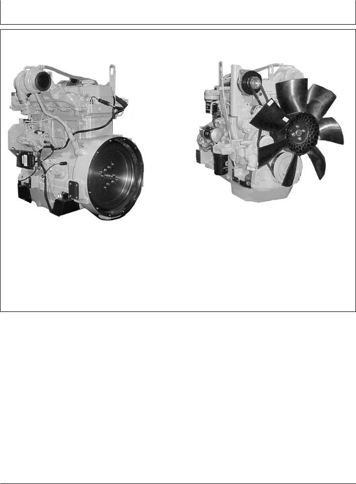
POWERTECH 4.5 L Engines With Electronic Fuel Systems (Tier 2 Emission Certified)
(Two-Valve Cylinder Head Models)
RG11931 –UN–06NOV01
4045 Engine (Stanadyne DE10 Injection Pump Shown)
RG11932 –UN–06NOV01
4045 Engine
POWERTECH is a trademark of Deere & Company. |
OUOD002,0000162 –19–04AUG06–1/1 |
080706
PN=6
Introduction
POWERTECH 6.8 L Engines With Electronic Fuel Systems (Tier 2 Emission Certified)
(Two-Valve Cylinder Head Models)
–UN–24OCT01 |
–UN–24OCT01 |
RG11933 |
RG11934 |
6068 Engine (Bosch VP44 Injection Pump Shown) |
6068 Engine |
POWERTECH is a trademark of Deere & Company. |
OUOD002,0000163 –19–04AUG06–1/1 |
080706
PN=7
Introduction
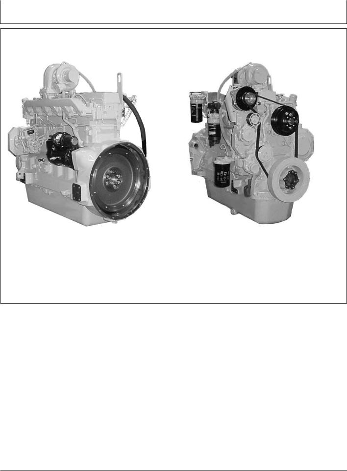
POWERTECH 4.5/6.8 L Engines With Electronic Fuel Systems (Tier 2 Emission Certified)
(Four-Valve Cylinder Head “475” Models)
–UN–24MAY02 |
–UN–24MAY02 |
|
RG12199 |
RG12200 |
|
6068HF475 Engine Shown (Level 11 Electronic Fuel System With |
6068HF475 Shown |
|
Denso High Pressure Common Rail) |
||
|
POWERTECH is a trademark of Deere & Company. |
OURGP11,000018B –19–04AUG06–1/1 |
080706
PN=8

Contents
Page |
Page |
Record Keeping
PowerTech Medallion . . . . . . . . . . . . . . . . . . . . . 01-1
Engine Serial Number Plate . . . . . . . . . . . . . . . . 01-1
Record Engine Serial Number . . . . . . . . . . . . . . 01-2
Engine Option Codes . . . . . . . . . . . . . . . . . . . . . 01-3
Record Engine Control Unit (ECU) Serial
Number. . . . . . . . . . . . . . . . . . . . . . . . . . . . . . 01-5
Record Fuel Injection Pump Model Number . . . . 01-5
Safety . . . . . . . . . . . . . . . . . . . . . . . . . . . . . . . . 05-1
Fuels, Lubricants, and Coolant
Diesel Fuel . . . . . . . . . . . . . . . . . . . . . . . . . . . . . 10-1 Lubricity of Diesel Fuel . . . . . . . . . . . . . . . . . . . . 10-1 Handling and Storing Diesel Fuel . . . . . . . . . . . . 10-2 Testing Diesel Fuel. . . . . . . . . . . . . . . . . . . . . . . 10-2 Bio-Diesel Fuel . . . . . . . . . . . . . . . . . . . . . . . . . . 10-3 Minimizing the Effect of Cold Weather on
Diesel Engines . . . . . . . . . . . . . . . . . . . . . . . . 10-4 Diesel Engine Break-In Oil . . . . . . . . . . . . . . . . . 10-5 Diesel Engine Oil . . . . . . . . . . . . . . . . . . . . . . . . 10-6 Diesel Engine Oil and Filter Service Intervals . . . 10-7 Mixing of Lubricants . . . . . . . . . . . . . . . . . . . . . . 10-9 Oil Filters . . . . . . . . . . . . . . . . . . . . . . . . . . . . . 10-10 OILSCAN and COOLSCAN . . . . . . . . . . . . . 10-10 Alternative and Synthetic Lubricants. . . . . . . . . 10-11 Lubricant Storage . . . . . . . . . . . . . . . . . . . . . . . 10-11 Grease . . . . . . . . . . . . . . . . . . . . . . . . . . . . . . . 10-12 Diesel Engine Coolant . . . . . . . . . . . . . . . . . . . 10-13 Drain Intervals for Diesel Engine Coolant . . . . 10-14 Supplemental Coolant Additives . . . . . . . . . . . . 10-15 Testing Diesel Engine Coolant . . . . . . . . . . . . . 10-15 Operating in Warm Temperature Climates . . . . 10-16 Disposing of Coolant . . . . . . . . . . . . . . . . . . . . 10-16
Instrument Panel Identification
Instrument Panels - Identification . . . . . . . . . . . . 15-1
Instrument Panel - Elect. Cont. Earlier Engines
Instrument Panel . . . . . . . . . . . . . . . . . . . . . . . . 16-1 Using Diagnostic Gauge to Access Engine
Information . . . . . . . . . . . . . . . . . . . . . . . . . . . 16-8
Using Touch Switches to Display
Information . . . . . . . . . . . . . . . . . . . . . . . . . . 16-10 Changing Units of Measure (English or
Metric). . . . . . . . . . . . . . . . . . . . . . . . . . . . . . 16-12 Viewing Engine Configuration Data . . . . . . . . . 16-14 Viewing Active Engine Service
Codes/Diagnostic Trouble Codes (DTCs) . . . 16-16 Viewing Stored Service
Codes/Diagnostic Trouble Codes
(DTCs) in the Engine ECU . . . . . . . . . . . . . . 16-17
Instrument Panel - Elect. Cont. Later Engines
Instrument Panels. . . . . . . . . . . . . . . . . . . . . . . . 17-1 Using Diagnostic Gauge to Access Engine
Information . . . . . . . . . . . . . . . . . . . . . . . . . . . 17-4 Main Menu Navigation . . . . . . . . . . . . . . . . . . . . 17-5 Engine Configuration Data . . . . . . . . . . . . . . . . . 17-6 Accessing Stored Trouble Codes . . . . . . . . . . . . 17-8 Accessing Active Trouble Codes . . . . . . . . . . . 17-10 Engine Shutdown Codes . . . . . . . . . . . . . . . . . 17-12 Adjusting Backlighting. . . . . . . . . . . . . . . . . . . . 17-13 Adjusting Contrast . . . . . . . . . . . . . . . . . . . . . . 17-15 Selecting Units Of Measurement . . . . . . . . . . . 17-17 Setup 1-Up Display . . . . . . . . . . . . . . . . . . . . . 17-20 Setup 4-Up Display . . . . . . . . . . . . . . . . . . . . . 17-26
Instrument Panel - Mech. Cont. “270” Engines
Instrument Panel (Earlier 4.5 L “270”
Engines) . . . . . . . . . . . . . . . . . . . . . . . . . . . . . 18-1
Instrument Panel (Later 4.5 L “270” Engines) . . . 18-3
Engine Operation - Except 4.5L “270” Engines
Engine Break-In Service . . . . . . . . . . . . . . . . . . . 19-1 Starting the Engine. . . . . . . . . . . . . . . . . . . . . . . 19-4 Normal Engine Operation . . . . . . . . . . . . . . . . . . 19-7 Warming Engine. . . . . . . . . . . . . . . . . . . . . . . . . 19-8 Cold Weather Operation . . . . . . . . . . . . . . . . . . . 19-9 Using a Booster Battery or Charger . . . . . . . . . 19-11 Avoid Excessive Engine Idling . . . . . . . . . . . . . 19-12 Changing Engine Speed. . . . . . . . . . . . . . . . . . 19-13 Stopping The Engine . . . . . . . . . . . . . . . . . . . . 19-16
Continued on next page
All information, illustrations and specifications in this manual are based on the latest information available at the time of publication. The right is reserved to make changes at any time without notice.
COPYRIGHT 2006
DEERE & COMPANY
Moline, Illinois
All rights reserved
A John Deere ILLUSTRUCTION Manual
Previous Editions
Copyright 2001, 2002, 2003, 2004, 2006
i |
080706 |
PN=1

Contents
Page |
Page |
Auxiliary Gear Drive Limitations . . . . . . . . . . . . 19-17
Generator Set (Standby) Applications. . . . . . . . 19-17
Engine Operation- 4.5 L “270” Engines
Normal Engine Operation . . . . . . . . . . . . . . . . . . 20-1 Break-In Service. . . . . . . . . . . . . . . . . . . . . . . . . 20-2 Auxiliary Gear Drive Limitations . . . . . . . . . . . . . 20-3 Generator Set (Standby) Power Units. . . . . . . . . 20-4 Starting The Engine . . . . . . . . . . . . . . . . . . . . . . 20-4 Cold Weather Starting . . . . . . . . . . . . . . . . . . . . 20-6 Warming Engine. . . . . . . . . . . . . . . . . . . . . . . . . 20-8 Avoid Excessive Engine Idling . . . . . . . . . . . . . . 20-9 Stopping the Engine . . . . . . . . . . . . . . . . . . . . . 20-10 Using a Booster Battery or Charger . . . . . . . . . 20-11
Lubrication and Maintenance
Observe Service Intervals. . . . . . . . . . . . . . . . . . 21-1
Use Correct Fuels, Lubricants, and Coolant . . . . 21-1
Lubrication and Maintenance Service
Interval Chart—Standard Industrial Engines . . 21-2
Lubrication and Maintenance Service
Interval Chart—Generator (Standby)
Applications . . . . . . . . . . . . . . . . . . . . . . . . . . 21-4
Lubrication & Maintenance/Daily
Daily Prestarting Checks . . . . . . . . . . . . . . . . . . 25-1
Lubrication & Maintenance/500 Hour/12 Month
Servicing Fire Extinguisher . . . . . . . . . . . . . . . . . 30-1
Checking Engine Mounts . . . . . . . . . . . . . . . . . . 30-1
Servicing Battery . . . . . . . . . . . . . . . . . . . . . . . . 30-2
Manual Belt Tensioner Adjustment . . . . . . . . . . . 30-4
Manual Belt Tensioner Adjustment Using
Belt Tension Tool (Alternate Method
For Engines Without Auxiliary Drive). . . . . . . . 30-5
Changing Engine Oil and Replacing Filter . . . . . 30-7
Checking Crankcase Vent System . . . . . . . . . . . 30-9
Checking Air Intake System . . . . . . . . . . . . . . . 30-11
Replacing Fuel Filter Elements . . . . . . . . . . . . . 30-12
Checking Belt Tensioner Spring Tension
and Belt Wear (Automatic Tensioner) . . . . . . 30-14
Checking Engine Electrical Ground
Connections . . . . . . . . . . . . . . . . . . . . . . . . . 30-16
Checking Cooling System. . . . . . . . . . . . . . . . . 30-16
Replenishing Supplemental Coolant
Additives (SCAs) Between Coolant
Changes . . . . . . . . . . . . . . . . . . . . . . . . . . . . 30-17
Testing Diesel Engine Coolant . . . . . . . . . . . . . 30-19
Pressure Testing Cooling System. . . . . . . . . . . 30-20
Checking and Adjusting Engine Speeds . . . . . . 30-21
Lubrication & Maint./2000 Hour/24 Month
Adjusting Variable Speed (Droop) — 4.5
L “270” Generator Set Engines Only. . . . . . . . 35-1
Checking Crankshaft Vibration Damper
(6-Cylinder Engine Only). . . . . . . . . . . . . . . . . 35-2 Flushing and Refilling Cooling System . . . . . . . . 35-3 Testing Thermostats Opening Temperature . . . . 35-6 Check and Adjust Valve Clearance (All
Engines Except 4045HF475 And
6068HF475) . . . . . . . . . . . . . . . . . . . . . . . . . . 35-9 Check and Adjust Valve Clearance
(4045HF475 And 6068HF475 Engines). . . . . 35-12 Test Glow Plugs for Continuity
(4045HF475 And 6068HF475 Engines). . . . . 35-15
Service as Required
Additional Service Information . . . . . . . . . . . . . . 40-1 Do Not Modify Fuel System . . . . . . . . . . . . . . . . 40-2 Adding Coolant. . . . . . . . . . . . . . . . . . . . . . . . . . 40-3 Replacing Single Stage Air Cleaner . . . . . . . . . . 40-5 Replacing Axial Seal Air Cleaner Filter
Element . . . . . . . . . . . . . . . . . . . . . . . . . . . . . 40-6 Replacing Radial Seal Air Cleaner Filter
Element . . . . . . . . . . . . . . . . . . . . . . . . . . . . . 40-8 Replacing Fan and Alternator Belts . . . . . . . . . 40-10 Checking Fuses . . . . . . . . . . . . . . . . . . . . . . . . 40-11 Checking Air Compressors . . . . . . . . . . . . . . . . 40-11 Bleeding the Fuel System (Engines With
Electronic Fuel Systems And Bosch VP44
Pump) . . . . . . . . . . . . . . . . . . . . . . . . . . . . . . 40-12 Bleed the Fuel System (Engines with
Electronic Fuel Systems and Stanadyne DE10 Pump) . . . . . . . . . . . . . . . . . . . . . . . . . . . . . . 40-14
Bleed the Fuel System (Engines with Electronic Fuel Systems and Denso High Pressure Common Rail) (4045HF475,
6068HF475) . . . . . . . . . . . . . . . . . . . . . . . . . 40-17 Bleed the Fuel System (4045DF270,
4045TF270) . . . . . . . . . . . . . . . . . . . . . . . . . 40-19
Troubleshooting
General Troubleshooting Information . . . . . . . . . 45-1 Precautions For Welding On Engines
Equipped With Electronic Engine Control Unit (ECU) . . . . . . . . . . . . . . . . . . . . . . . . . . . . . . . 45-2
Precautions for Electrical System When
Steam Cleaning Engine . . . . . . . . . . . . . . . . . 45-2 Engine Wiring Layout (Electronic Fuel
System With Stanadyne DE10 Injection
Pump) . . . . . . . . . . . . . . . . . . . . . . . . . . . . . . . 45-3 Engine Wiring Layout (Electronic Fuel
System With Bosch VP44 Injection Pump) . . . 45-4
Continued on next page
ii |
080706 |
PN=2
Contents
Page |
Page |
Engine Wiring Layout (Electronic Fuel
System With Denso High Pressure Common Rail)(4045HF475,6068HF475). . . . . . . . . . . . . 45-5
Engine Wiring Diagram (With Earlier
Electronic Instrument Panel) . . . . . . . . . . . . . . 45-6 Engine Wiring Diagram (Engines With
Electronic Instrument Panel) . . . . . . . . . . . . . . 45-7 Engine Wiring Diagram (With Later
Full-Featured Electronic Instrument Panel) . . . 45-8 Engine Wiring Diagram (With Later
Full-Featured Electronic Instrument Panel)— Continued . . . . . . . . . . . . . . . . . . . . . . . . . . . . 45-9
Engine Troubleshooting . . . . . . . . . . . . . . . . . . 45-10 Blink Code Method for Retrieving
Diagnostic Trouble Codes (All Except
Early VP44 Pump Engines). . . . . . . . . . . . . . 45-17 Blink Code Method for Retrieving
Diagnostic Trouble Codes (Early VP44
Pump Engines Only) . . . . . . . . . . . . . . . . . . . 45-18 Instrument Panel Method for Retrieving
Diagnostic Trouble Codes . . . . . . . . . . . . . . . 45-20 Displaying Of Diagnostic Trouble Codes
(DTCs) . . . . . . . . . . . . . . . . . . . . . . . . . . . . . 45-21 Listing of Diagnostic Trouble Codes (DTCs)
(Engines With Electronic Fuel
Systems And Stanadyne DE10 Pump) . . . . . 45-22 Listing of Diagnostic Trouble Codes (DTCs)
(Engines With Electronic Fuel
Systems And Bosch VP44 Pump). . . . . . . . . 45-24 Listing of Diagnostic Trouble Codes (DTCs)
(Engines With Electronic Fuel Systems
And Denso High Pressure Common Rail) (“475” Engines) . . . . . . . . . . . . . . . . . . . . . . . . . . . . 45-26
Error Codes Displayed (With Early
Electronic Panels) . . . . . . . . . . . . . . . . . . . . . 45-28 Intermittent Fault Diagnostics (With
Electronic Controls). . . . . . . . . . . . . . . . . . . . 45-29 Displaying Diagnostic Gauge Software
(Later Engines) . . . . . . . . . . . . . . . . . . . . . . . 45-29
Storage
Engine Storage Guidelines . . . . . . . . . . . . . . . . . 50-1 Preparing Engine for Long Term Storage . . . . . . 50-2 Removing Engine from Long Term Storage . . . . 50-3
Lubrication and Maintenance Records
Using Lubrication and Maintenance Records . . . 60-1
Daily (Prestarting) Service . . . . . . . . . . . . . . . . . 60-1
500 Hour/12 Month Service . . . . . . . . . . . . . . . . 60-2
2000 Hour/24 Month Service . . . . . . . . . . . . . . . 60-3
Service as Required . . . . . . . . . . . . . . . . . . . . . . 60-4
Emission System Warranty
U.S. EPA Emmission Control Warranty
Statement . . . . . . . . . . . . . . . . . . . . . . . . . . . . 65-1
Emission Control System Certification Label. . . . 65-2
Specifications
General OEM Engine Specifications. . . . . . . . . . 55-1
Engine Power Ratings And Fuel System
Specifications . . . . . . . . . . . . . . . . . . . . . . . . . 55-3
Engine Crankcase Oil Fill Quantities . . . . . . . . . 55-6
Unified Inch Bolt and Screw Torque Values . . . . 55-7
Metric Bolt and Screw Torque Values. . . . . . . . . 55-8
iii |
080706 |
PN=3

Contents
iv |
080706 |
PN=4
Record Keeping
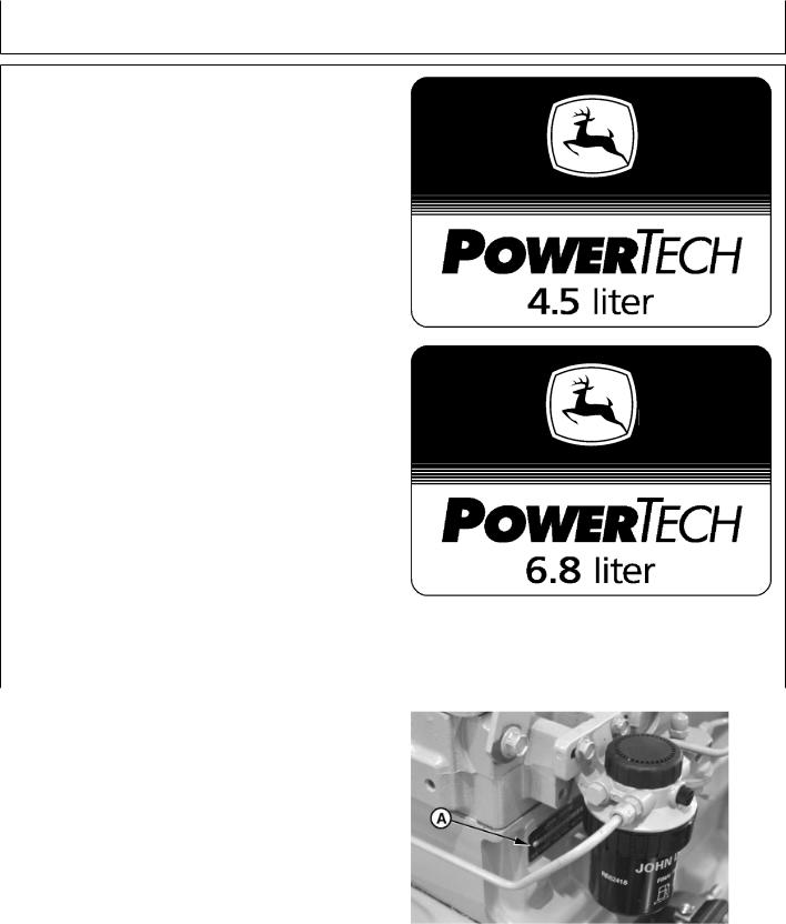
POWERTECH Medallion
A medallion is located on the rocker arm cover which identifies each engine as a John Deere POWERTECH engine.
NOTE: Four-valve head engines also have “16V” or “24V” printed on their medallions. The 4045HF475 has “16V” to denote 16 valves total while 6068HF475 has “24V” to denote 24 valves total.
RG11608 –UN–17OCT01
|
|
|
–UN–17OCT01 |
|
|
|
RG11609 |
POWERTECH is a trademark of Deere & Company. |
OURGP11,0000274 |
–19–04AUG06–1/1 |
|
|
|
|
|
Engine Serial Number Plate |
|
|
|
Each engine has a 13-digit John Deere engine serial |
|
|
|
number. The first two digits identify the factory that |
|
|
|
produced the engine: |
|
–UN–15JAN99 |
|
• |
“CD” = Saran, France |
|
|
|
|
||
• |
“PE” = Torreon, Mexico |
|
|
• |
“T0” = Dubuque, Iowa |
|
|
• |
“J0” = Rosario, Argentina |
|
RG8007 |
The engine’s serial number plate (A) is located on the |
|
||
right-hand side of cylinder block behind the fuel filter. |
13-Digit Engine Serial Number Plate |
|
|
|
A—Serial Number Plate |
|
|
|
|
RG,RG34710,5506 |
–19–27JUL06–1/1 |
|
01-1 |
|
080706 |
PN=11

Record Keeping
Record Engine Serial Number
Record all of the numbers and letters found on your engine serial number plate in the spaces provided below.
This information is very important for repair parts or warranty information.
Engine Serial Number (B)
Engine Model Number (C)
Coefficient of Absorption Value (D)
(Saran Engines Only)
NOTE: Effective in April 2005, engine serial numbers were changed at the 7th digit to show the Emission Level. Previously this digit identified the type of aspiration.
On earlier engines the 7th digit showed the aspiration code as follows:
•“A” for turbocharged with air-to-water aftercooler
•“D” for naturally aspirated
•“H” for turbocharged with air-to-air aftercooler
•“T” for turbocharged only
On later engines after April 2005, the seventh digit will be as follows:
•“B” for non-certified engines
•“C” for Tier 1 / Stage I engines
•“G” for Tier 2 / Stage II engines
•“L” for Tier 3 / Stage IIIA engines
01-2
RG11949 –UN–07NOV01
Saran Engine Serial Number Plate
RG11948 –UN–06NOV01
Torreon Engine Serial Number Plate
OURGP11,0000070 –19–27JUL06–1/1
080706
PN=12
Record Keeping
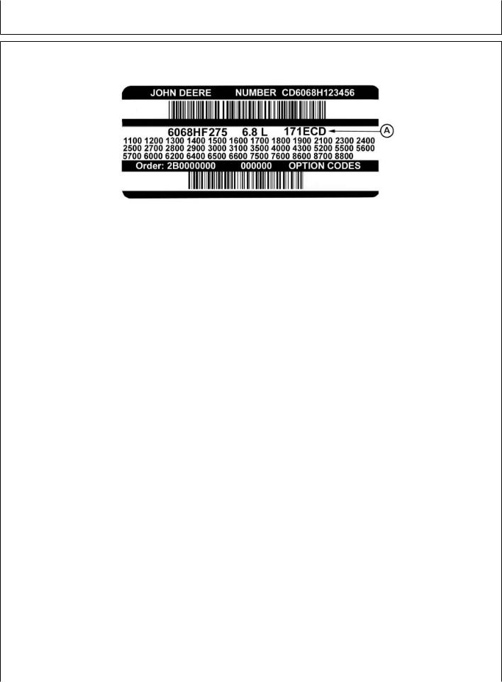
Engine Option Codes
RG11946 –UN–06NOV01
A—Engine Base Code
In addition to the serial number plate, OEM engines have an engine option code label affixed to the rocker arm cover. These codes indicate which of the engine options were installed on your engine at the factory. When in need of parts or service, furnish your authorized servicing dealer or engine distributor with these numbers.
The engine option code label includes an engine base code (A). This base code must also be recorded along with the option codes.
The first two digits of each code identify a specific group, such as alternators. The last two digits of each code identify one specific option provided on your engine, such as a 12-volt, 55-amp alternator.
NOTE: These option codes are based on the latest information available at the time of publication. The right is reserved to make changes at any time without notice.
If an engine is ordered without a particular component, the last two digits of that functional group option code will be 99, 00, or XX. The list on the next page shows only the first two digits of the code numbers. For future reference such as ordering repair parts, it is important to have these code numbers available. To ensure this availability, enter the third and fourth digits shown on your engine option code label in the spaces provided on the following page.
Continued on next page |
RG,RG34710,5508 –19–27JUL06–1/2 |
01-3 |
080706 |
PN=13

Record Keeping
NOTE: Your engine option code label may not contain all option codes if an option has been added after the engine left the producing factory.
If option code label is lost or destroyed, consult your servicing dealer or engine distributor selling the engine for a replacement.
Option Codes |
Description |
||
11 |
|
|
Rocker Arm Cover |
12 |
|
Oil Fill Inlet |
|
13 |
|
Crankshaft Pulley/Damper |
|
|
|||
14 |
|
Flywheel Housing |
|
|
|||
15 |
|
Flywheel |
|
16 |
|
Fuel Injection Pump |
|
|
|||
17 |
|
Air Inlet |
|
|
|||
18 |
|
Air Cleaner |
|
19 |
|
Oil Pan |
|
20 |
|
Coolant Pump |
|
|
|||
21 |
|
Thermostat Cover |
|
|
|||
22 |
|
Thermostat |
|
23 |
|
Fan Drive |
|
|
|||
24 |
|
Fan Belt |
|
|
|||
25 |
|
Fan |
|
26 |
|
Engine Coolant Heater |
|
27 |
|
Radiator |
|
|
|||
28 |
|
Exhaust Manifold |
|
|
|||
29 |
|
Crankcase Ventilator System |
|
30 |
|
Starter Motor |
|
|
|||
31 |
|
Alternator |
|
|
|||
32 |
|
Instrument Panel |
|
33 |
|
Tachometer |
|
35 |
|
Fuel Filters |
|
|
|||
36 |
|
Front Plate |
|
|
|||
37 |
|
Fuel Transfer Pump |
|
39 |
|
Thermostat Housing |
|
|
|||
40 |
|
Oil Dipstick |
|
|
|||
41 |
|
Belt-Driven Front Auxiliary Drive |
|
43 |
|
Starting Aid |
|
44 |
|
Timing Gear Cover With Gears |
|
|
|||
46 |
|
Cylinder Block With Liners and Camshaft |
|
|
|||
47 |
|
Crankshaft and Bearings |
|
48 |
|
Connecting Rods and Pistons |
|
|
|||
49 |
|
Valve Actuating Mechanism |
|
|
|||
An additional option code label may also be delivered with the engine. Place this sticker or tag, for reference, either on this page or in the engine owner’s warranty booklet under OPTION CODES title.
Option Codes |
Description |
|||
50 |
|
|
Oil Pump |
|
51 |
|
|
Cylinder Head With Valves |
|
52 |
|
|
Auxiliary Gear Drive |
|
|
|
|||
53 |
|
|
Fuel Heater |
|
|
|
|||
55 |
|
|
Shipping Stand |
|
56 |
|
|
Paint Option |
|
|
|
|||
57 |
|
|
Coolant Pump Inlet |
|
|
|
|||
59 |
|
|
Oil Cooler |
|
60 |
|
|
Add-on Auxiliary Drive Pulley |
|
62 |
|
|
Alternator Mounting Bracket |
|
|
|
|||
63 |
|
|
Low Pressure Fuel Line |
|
|
|
|||
64 |
|
|
Exhaust Elbow |
|
65 |
|
|
Turbocharger |
|
|
|
|||
66 |
|
|
|
Coolant Temperature Switch |
|
|
|
||
67 |
|
|
|
Electronic Sensors (Base Engine) |
68 |
|
|
Crankshaft Rear Damper |
|
69 |
|
|
Engine Serial Number Plate |
|
|
|
|||
71 |
|
|
Engine Oil Bypass Filter |
|
|
|
|||
72 |
|
|
ECU Electronic Software Option |
|
74 |
|
|
Air Conditioning (Freon) Compressor |
|
|
|
|||
75 |
|
|
Air Restriction Indicator |
|
|
|
|||
76 |
|
|
Pressure Switches and Sensors |
|
77 |
|
|
Timing Gear Cover |
|
78 |
|
|
Air Compressor |
|
|
|
|||
79 |
|
|
Engine Certification |
|
|
|
|||
81 |
|
|
Primary Fuel Filter And Water Separator |
|
83 |
|
|
Electronic Software (Vehicle Option) |
|
|
|
|||
84 |
|
|
Electrical Wiring Harness |
|
|
|
|||
86 |
|
|
Fan Pulley |
|
87 |
|
|
Belt Tensioner |
|
88 |
|
|
Oil Filter |
|
|
|
|||
95 |
|
|
Special Equipment (Factory Installed) |
|
|
|
|||
96 |
|
|
Engine Installation Kit |
|
97 |
|
|
Special Equipment (Field Installed) |
|
|
|
|||
98 |
|
|
Shipping (Engine Hanger Straps) |
|
|
|
|||
99 |
|
Service Only Items |
||
|
||||
Engine Base Code (See “A” on previous page.)
RG,RG34710,5508 –19–27JUL06–2/2
01-4 |
080706 |
PN=14
Record Keeping
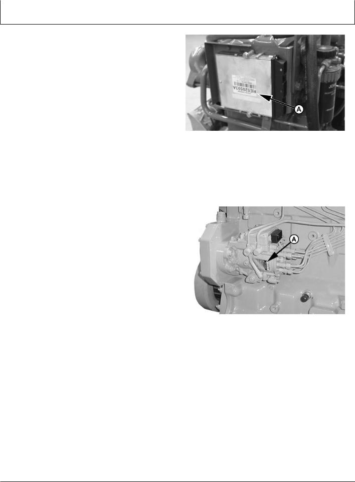
Record Engine Control Unit (ECU) Serial |
|
|||||||||
Number |
|
|
|
|
|
|||||
Record the part number and serial number information |
|
|||||||||
found on the serial number label (A) on the Engine |
|
|||||||||
Control Unit (ECU) mounted on or near the engine. |
–UN–18NOV04 |
|||||||||
Part No. |
|
|
|
|
|
|
|
|
|
|
|
|
|
|
|
|
|
|
|
|
|
Serial No. |
|
|
|
|
|
|
|
|
RG13799 |
|
|
|
|
|
|
|
|
|
|
|
|
A—Serial Number Label |
|
|
|
Record Engine Control Unit (ECU) Serial Number |
||||||
|
|
|
|
|
|
|
|
|
OURGP12,00000AD |
–19–27JUL06–1/1 |
|
|
|
|
|
|
|
||||
Record Fuel Injection Pump Model Number |
|
|||||||||
Record the fuel injection pump model and serial |
|
|||||||||
information found on the serial number plate (A). |
|
|||||||||
Model No. |
|
|
RPM |
|
|
|
||||
|
|
|
|
|||||||
Manufacturer’s No. |
|
|
|
|
|
–UN–06NOV01 |
||||
Serial No. |
|
|
|
|
|
|
|
|||
|
|
|
|
|
|
|||||
A—Serial Number Plate |
|
|
|
|
RG11943 |
|||||
|
|
|
|
|
|
|
|
|
|
|
|
|
|
|
|
|
|
|
|
Record Injection Pump Serial Number |
|
|
|
|
|
|
|
|
|
|
RG,RG34710,5511 |
–19–27JUL06–1/1 |
01-5 |
080706 |
PN=15

Safety
Recognize Safety Information
This is a safety-alert symbol. When you see this symbol on your machine or in this manual, be alert to the potential for personal injury.
Follow recommended precautions and safe operating practices.
Understand Signal Words
A signal word—DANGER, WARNING, or CAUTION—is used with the safety-alert symbol. DANGER identifies the most serious hazards.
DANGER or WARNING safety signs are located near specific hazards. General precautions are listed on CAUTION safety signs. CAUTION also calls attention to safety messages in this manual.
Follow Safety Instructions
Carefully read all safety messages in this manual and on your machine safety signs. Keep safety signs in good condition. Replace missing or damaged safety signs. Be sure new equipment components and repair parts include the current safety signs. Replacement safety signs are available from your John Deere dealer.
Learn how to operate the machine and how to use controls properly. Do not let anyone operate without instruction.
Keep your machine in proper working condition. Unauthorized modifications to the machine may impair the function and/or safety and affect machine life.
If you do not understand any part of this manual and need assistance, contact your John Deere dealer.
05-1
–UN–07DEC88 T81389 DX,ALERT –19–29SEP98–1/1
–19–30SEP88 TS187 DX,SIGNAL –19–03MAR93–1/1
TS201 –UN–23AUG88
DX,READ –19–03MAR93–1/1
080706
PN=16
Safety
Replace Safety Signs
Replace missing or damaged safety signs. See the machine operator’s manual for correct safety sign placement.
Prevent Bypass Starting
Avoid possible injury or death from engine runaway.
Do not start engine by shorting across starter terminal. Engine will start with PTO engaged if normal circuitry is bypassed.
Start engine only from operator’s station with PTO disengaged or in neutral.
Handle Fuel Safely—Avoid Fires
Handle fuel with care: it is highly flammable. Do not refuel the machine while smoking or when near open flame or sparks.
Always stop engine before refueling machine. Fill fuel tank outdoors.
Prevent fires by keeping machine clean of accumulated trash, grease, and debris. Always clean up spilled fuel.
05-2
–UN–23AUG88 TS201 DX,SIGNS1 –19–04JUN90–1/1
RG5419 –UN–28FEB89
Prevent Bypass Starting
RG,RG34710,7508 –19–27JUL06–1/1
TS202 –UN–23AUG88
DX,FIRE1 –19–03MAR93–1/1
080706
PN=17
Safety
Prepare for Emergencies
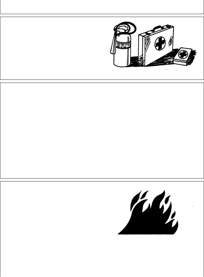
Be prepared if a fire starts.
Keep a first aid kit and fire extinguisher handy.
Keep emergency numbers for doctors, ambulance service, hospital, and fire department near your telephone.
–UN–23AUG88 TS291 DX,FIRE2 –19–03MAR93–1/1
Handle Starting Fluid Safely
Starting fluid is highly flammable.
Keep all sparks and flame away when using it. Keep starting fluid away from batteries and cables.
To prevent accidental discharge when storing the pressurized can, keep the cap on the container, and store in a cool, protected location.
Do not incinerate or puncture a starting fluid container.
 TS1356 –UN–18MAR92
Handle Fluids Safely—Avoid Fires
When you work around fuel, do not smoke or work near heaters or other fire hazards.
Store flammable fluids away from fire hazards. Do not incinerate or puncture pressurized containers.
Make sure machine is clean of trash, grease, and debris.
Do not store oily rags; they can ignite and burn spontaneously.
DX,FIRE3 –19–16APR92–1/1
TS227 –UN–23AUG88
DX,FLAME |
–19–29SEP98–1/1 |
05-3 |
080706 |
PN=18
Safety
Service Engines Safely
Tie long hair behind your head. Do not wear a necktie, scarf, loose clothing, or necklace when you work near machine tools or moving parts. If these items were to get caught, severe injury could result.
Remove rings and other jewelry to prevent electrical shorts and entanglement in moving parts.
Wear Protective Clothing
Wear close fitting clothing and safety equipment appropriate to the job.
Prolonged exposure to loud noise can cause impairment or loss of hearing.
Wear a suitable hearing protective device such as earmuffs or earplugs to protect against objectionable or uncomfortable loud noises.
Operating equipment safely requires the full attention of the operator. Do not wear radio or music headphones while operating machine.
Protect Against Noise
Prolonged exposure to loud noise can cause impairment or loss of hearing.
Wear a suitable hearing protective device such as earmuffs or earplugs to protect against objectionable or uncomfortable loud noises.
05-4
TS228 –UN–23AUG88
Moving Parts
OURGP12,00001DA –19–27JUL06–1/1
TS206 –UN–23AUG88
DX,WEAR –19–10SEP90–1/1
–UN–23AUG88 TS207 DX,NOISE –19–03MAR93–1/1
080706
PN=19
Safety
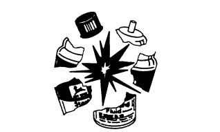
Handle Chemical Products Safely
Direct exposure to hazardous chemicals can cause serious injury. Potentially hazardous chemicals used with John Deere equipment include such items as lubricants, coolants, paints, and adhesives.
A Material Safety Data Sheet (MSDS) provides specific details on chemical products: physical and health hazards, safety procedures, and emergency response techniques.
Check the MSDS before you start any job using a hazardous chemical. That way you will know exactly what the risks are and how to do the job safely. Then follow procedures and recommended equipment.
(See your John Deere dealer for MSDS’s on chemical products used with John Deere equipment.)
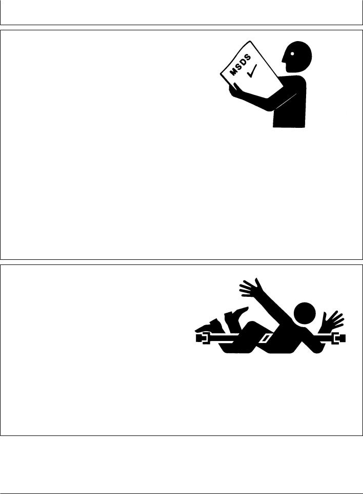
Stay Clear of Rotating Drivelines
Entanglement in rotating driveline can cause serious injury or death.
Keep master shield and driveline shields in place at all times. Make sure rotating shields turn freely.
Wear close-fitting clothing. Stop the engine and be sure PTO driveline is stopped before making adjustments, connections, or performing any type of service on the engine or PTO-driven equipment.
05-5
TS1132 –UN–26NOV90
DX,MSDS,NA –19–03MAR93–1/1
TS1644 –UN–22AUG95
Rotating Drivelines
OUO1004,0000BD8 –19–27JUL06–1/1
080706
PN=20
Safety
Practice Safe Maintenance
Understand service procedure before doing work. Keep area clean and dry.
Never lubricate, service, or adjust machine while it is moving. Keep hands, feet , and clothing from power-driven parts. Disengage all power and operate controls to relieve pressure. Lower equipment to the ground. Stop the engine. Remove the key. Allow machine to cool.
Securely support any machine elements that must be raised for service work.
Keep all parts in good condition and properly installed. Fix damage immediately. Replace worn or broken parts. Remove any buildup of grease, oil, or debris.
On self-propelled equipment, disconnect battery ground cable (-) before making adjustments on electrical systems or welding on machine.
On towed implements, disconnect wiring harnesses from tractor before servicing electrical system components or welding on machine.
Work In Ventilated Area
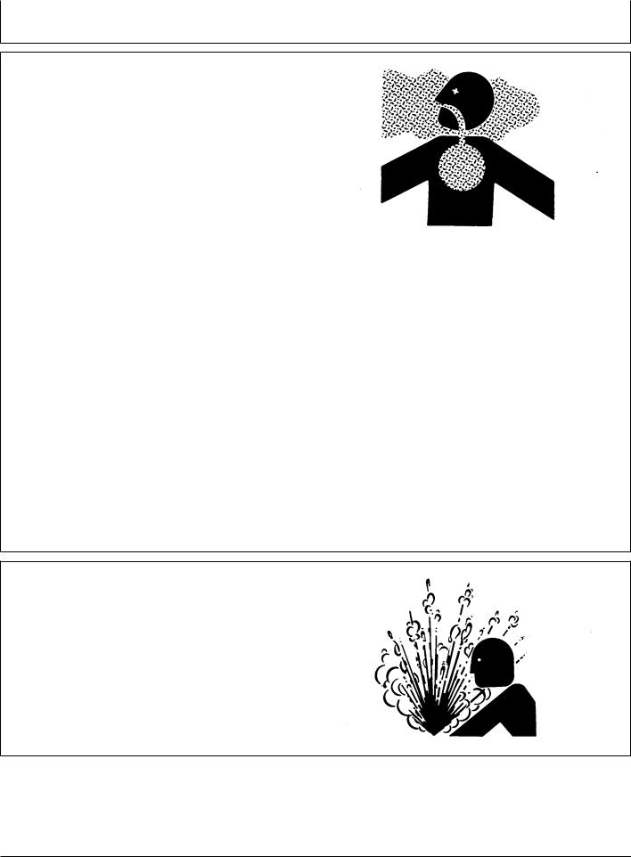
Engine exhaust fumes can cause sickness or death. If it is necessary to run an engine in an enclosed area, remove the exhaust fumes from the area with an exhaust pipe extension.
If you do not have an exhaust pipe extension, open the doors and get outside air into the area
05-6
TS218 –UN–23AUG88
DX,SERV –19–17FEB99–1/1
–UN–23AUG88 TS220 DX,AIR –19–17FEB99–1/1
080706
PN=21
Safety
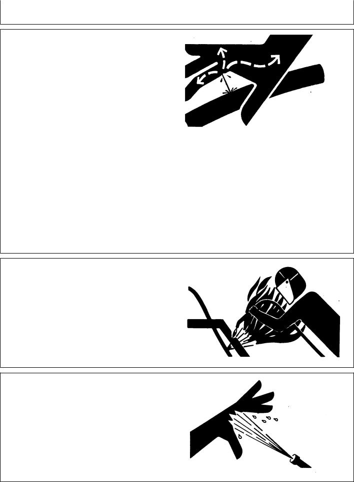
Avoid High-Pressure Fluids
Escaping fluid under pressure can penetrate the skin causing serious injury.
Avoid the hazard by relieving pressure before disconnecting hydraulic or other lines. Tighten all connections before applying pressure.
Search for leaks with a piece of cardboard. Protect hands and body from high pressure fluids.
If an accident occurs, see a doctor immediately. Any fluid injected into the skin must be surgically removed within a few hours or gangrene may result. Doctors unfamiliar with this type of injury should reference a knowledgeable medical source. Such information is available from Deere & Company Medical Department in Moline, Illinois, U.S.A.
Avoid Heating Near Pressurized Fluid Lines
Flammable spray can be generated by heating near pressurized fluid lines, resulting in severe burns to yourself and bystanders. Do not heat by welding, soldering, or using a torch near pressurized fluid lines or other flammable materials. Pressurized lines can accidentally burst when heat goes beyond the immediate flame area.
Do Not Open High-Pressure Fuel System
High-pressure fluid remaining in fuel lines can cause serious injury. Do not disconnect or attempt repair of fuel lines, sensors, or any other components between the high-pressure fuel pump and nozzles on engines with High Pressure Common Rail (HPCR) fuel system.
Only technicians familiar with this type of system can perform repairs. (See your John Deere dealer.)
05-7
X9811 –UN–23AUG88
DX,FLUID –19–03MAR93–1/1
–UN–15MAY90 TS953 DX,TORCH –19–10DEC04–1/1
–UN–18MAR92 TS1343 DX,WW,HPCR1 –19–07JAN03–1/1
080706
PN=22
Safety
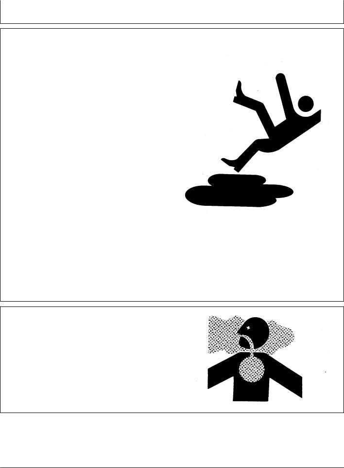
Remove Paint Before Welding or Heating
Avoid potentially toxic fumes and dust.
Hazardous fumes can be generated when paint is heated by welding, soldering, or using a torch.
Remove paint before heating:
•Remove paint a minimum of 100 mm (4 in.) from area to be affected by heating. If paint cannot be removed, wear an approved respirator before heating or welding.
•If you sand or grind paint, avoid breathing the dust. Wear an approved respirator.
•If you use solvent or paint stripper, remove stripper with soap and water before welding. Remove solvent or paint stripper containers and other flammable material from area. Allow fumes to disperse at least 15 minutes before welding or heating.
Do not use a chlorinated solvent in areas where welding will take place.
Do all work in an area that is well ventilated to carry toxic fumes and dust away.
Dispose of paint and solvent properly.
Service Cooling System Safely
Explosive release of fluids from pressurized cooling system can cause serious burns.
Shut off engine. Only remove filler cap when cool enough to touch with bare hands. Slowly loosen cap to first stop to relieve pressure before removing completely.
05-8
TS220 –UN–23AUG88
DX,PAINT –19–24JUL02–1/1
–UN–23AUG88 TS281 DX,RCAP –19–04JUN90–1/1
080706
PN=23
Safety
Install Fan Guards
Rotating cooling system fans can cause serious injury.
Keep fan guards in place at all times during engine operation. Wear close fitting clothes. Stop the engine and be sure fan is stopped before making adjustments or connections, or cleaning near the front of the engine.
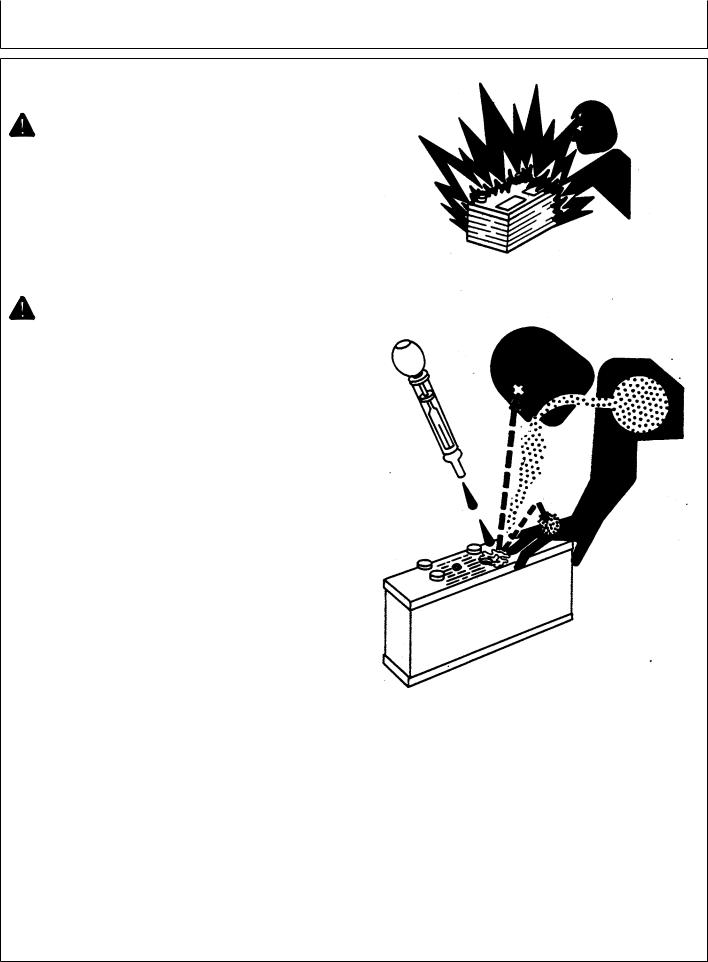
Avoid Hot Parts
Avoid skin contact with exhaust manifolds, turbochargers and mufflers. Keep flammable materials clear of the turbocharger.
External dry exhaust parts become very hot during operation. Turbochargers and exhaust manifolds may reach temperatures as high as 600°C (1112°F) under full load. This may ignite paper, cloth or wooden materials. Parts on engines that have been at full load and reduced to no load idle will maintain approximately 150°C (302°F).
05-9
TS677 –UN–21SEP89
Rotating Fan
OUOD006,000009D –19–27JUL06–1/1
TS271 –UN–23AUG88
Hot Surface
OURGP12,0000135 –19–27JUL06–1/1
080706
PN=24
Safety
Avoid Harmful Asbestos Dust
Avoid breathing dust that may be generated when handling components containing asbestos fibers. Inhaled asbestos fibers may cause lung cancer.
Components in products that may contain asbestos fibers are brake pads, brake band and lining assemblies, clutch plates, and some gaskets. The asbestos used in these components is usually found in a resin or sealed in some way. Normal handling is not hazardous as long as airborne dust containing asbestos is not generated.
Avoid creating dust. Never use compressed air for cleaning. Avoid brushing or grinding material containing asbestos. When servicing, wear an approved respirator. A special vacuum cleaner is recommended to clean asbestos. If not available, apply a mist of oil or water on the material containing asbestos.
Keep bystanders away from the area.
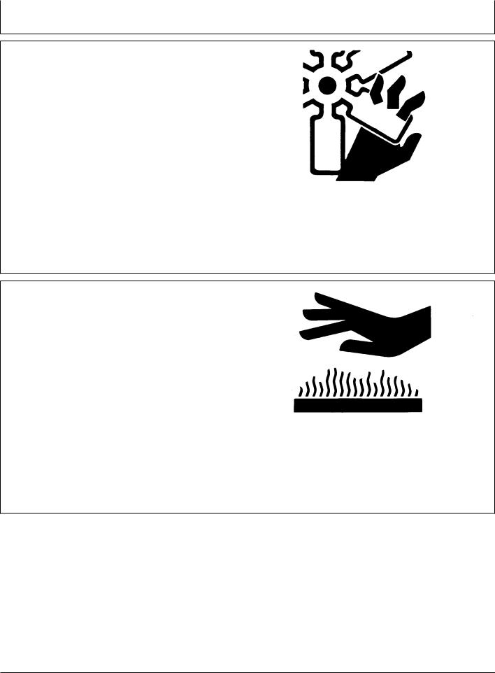
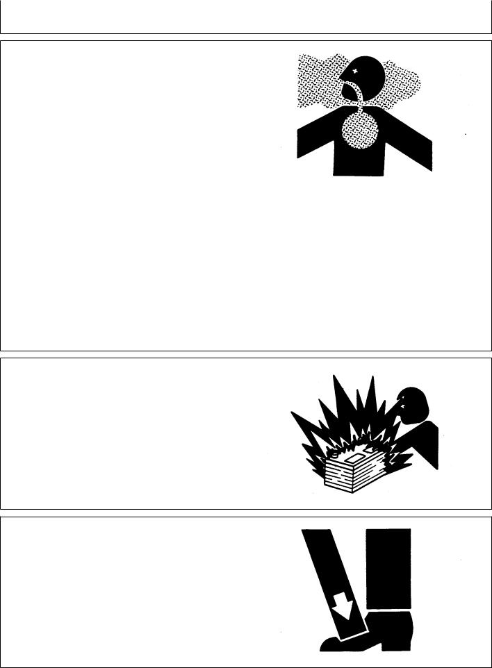
Prevent Battery Explosions
Keep sparks, lighted matches, and open flame away from the top of battery. Battery gas can explode.
Never check battery charge by placing a metal object across the posts. Use a volt-meter or hydrometer.
Do not charge a frozen battery; it may explode. Warm battery to 16°C (60°F).
Use Proper Lifting Equipment
Lifting heavy components incorrectly can cause severe injury or machine damage.
Follow recommended procedure for removal and installation of components in the manual.
05-10
TS220 –UN–23AUG88
DX,DUST –19–15MAR91–1/1
–UN–23AUG88 TS204 DX,SPARKS –19–03MAR93–1/1
–UN–23AUG88 TS226 DX,LIFT –19–04JUN90–1/1
080706
PN=25

Safety
Use Proper Tools
Use tools appropriate to the work. Makeshift tools and procedures can create safety hazards.
Use power tools only to loosen threaded parts and fasteners.
For loosening and tightening hardware, use the correct size tools. DO NOT use U.S. measurement tools on metric fasteners. Avoid bodily injury caused by slipping wrenches.
Use only service parts meeting John Deere specifications.
TS779 –UN–08NOV89
DX,REPAIR –19–17FEB99–1/1
05-11 |
080706 |
PN=26
Safety
Handling Batteries Safely
CAUTION: Battery gas can explode. Keep sparks and flames away from batteries. Use a flashlight to check battery electrolyte level.
Never check battery charge by placing a metal object across the posts. Use a voltmeter or hydrometer.
Always remove grounded (—) battery clamp first and replace it last.
CAUTION: Sulfuric acid in battery electrolyte is poisonous. It is strong enough to burn skin, eat holes in clothing, and cause blindness if splashed into eyes.
Avoid the hazard by:
1.Filling batteries in a well-ventilated area.
2.Wearing eye protection and rubber gloves.
3.Avoiding breathing fumes when electrolyte is added.
4.Avoiding spilling or dripping electrolyte.
5.Using proper jump start procedure.
If you spill acid on yourself:
1.Flush your skin with water.
2.Apply baking soda or lime to help neutralize the acid.
3.Flush your eyes with water for 15—30 minutes. Get medical attention immediately.
If acid is swallowed:
1.Do not induce vomiting.
2.Drink large amounts of water or milk, but do not exceed 2 L (2 qt.).
3.Get medical attention immediately.
WARNING: Battery posts, terminals, and related accessories contain lead and lead compounds, chemicals known to the State of California to cause cancer and reproductive harm. Wash hands after handling.
05-12
TS204 –UN–23AUG88
Explosion
TS203 –UN–23AUG88
Acid
DPSG,OUO1004,2758 –19–27JUL06–1/1
080706
PN=27
Safety
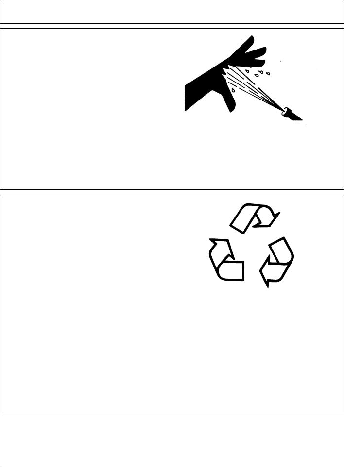
Protect Against High Pressure Spray
Spray from high pressure nozzles can penetrate the skin and cause serious injury. Keep spray from contacting hands or body.
If an accident occurs, see a doctor immediately. Any high pressure spray injected into the skin must be surgically removed within a few hours or gangrene may result. Doctors unfamiliar with this type of injury should reference a knowledgeable medical source. Such information is available from Deere & Company Medical Department in Moline, Illinois, U.S.A.
TS1343 –UN–18MAR92
Dispose of Waste Properly
Improperly disposing of waste can threaten the environment and ecology. Potentially harmful waste used with John Deere equipment include such items as oil, fuel, coolant, brake fluid, filters, and batteries.
Use leakproof containers when draining fluids. Do not use food or beverage containers that may mislead someone into drinking from them.
Do not pour waste onto the ground, down a drain, or into any water source.
Air conditioning refrigerants escaping into the air can damage the Earth’s atmosphere. Government regulations may require a certified air conditioning service center to recover and recycle used air conditioning refrigerants.
Inquire on the proper way to recycle or dispose of waste from your local environmental or recycling center, or from your John Deere dealer.
DX,SPRAY –19–16APR92–1/1
TS1133 –UN–26NOV90
DX,DRAIN –19–03MAR93–1/1
05-13 |
080706 |
PN=28
Loading...