


O P E R A T O R ’ S M A N U A L
GROOMING MOWERS
GM1048E
GM1060E
GM1072E
Manual 5BP960379B
Date 11/11/2010

SAFETY
Take note! This safety alert symbol found throughout this manual is used to call your attention to instructions involving your personal safety and the safety of others. Failure to follow these instructions can result in injury or death.
This symbol means:
ATTENTION!
BECOME ALERT!
YOUR SAFETY IS INVOLVED!
Signal Words
Note the use of the signal words DANGER, WARNING and CAUTION with the safety messages. The appropriate signal words for each have been selected using the following guidelines:
DANGER: Indicates an imminently hazardous situation that, if not avoided, will result in death or serious injury.
WARNING: Indicates a potentially hazardous situation that, if not avoided, could result in death or serious injury, and includes hazards that are exposed when guards are removed. It may also be used to alert against unsafe practices.
CAUTION: Indicates a potentially hazardous situation that, if not avoided, may result in minor or moderate injury.
INDEX
1 - GENERAL INFORMATION |
4 |
|
1.01 |
- General |
4 |
1.02 |
- Warranty Information |
4 |
1.03 |
- Model and Serial Number ID |
5 |
1.04 |
- Assembly Instructions |
5 |
1.05 |
- Quick Hitch Adapter Assembly and Operation |
7 |
2 - SAFETY PRECAUTIONS |
10 |
|
2.01 |
- Preparation |
10 |
2.02 |
- Starting and Stopping |
11 |
2.03 |
- Messages and Signs |
11 |
3 - OPERATION |
14 |
|
3.01 |
- Operational Safety |
14 |
3.02 |
- Set Up |
16 |
3.03 |
- Cutting Height Adjustment |
17 |
3.04 |
- Pre-Operational Check |
18 |
3.05 |
- Attaching to the Tractor |
18 |
3.06 |
- Start Up |
19 |
3.07 |
- Working Speed |
20 |
3.08 |
- Operating Techniques |
21 |
3.09 |
- Uneven Terrain |
22 |
3.10 |
- Removing Mower from the Tractor |
23 |
3.11 |
- Transport |
23 |
4 - MAINTENANCE |
24 |
|
4.01 |
- Maintenance Safety |
24 |
4.02 |
- Service |
25 |
4.03 |
- Blade Maintenance |
26 |
4.04 |
- Belt Tension |
28 |
4.05 |
- Belt Replacement |
29 |
4.06 |
- Driveline |
30 |
5 - REPAIR PROCEDURES |
33 |
|
5.01 |
- Gearbox |
33 |
5.02 |
- Blade Spindle |
33 |
5.03 |
- Suggested Spare Parts |
33 |
5.04 |
- Storage |
34 |
6 - TROUBLESHOOTING |
35 |
|
7 - PRE-DELIVERY CHECKLIST |
36 |
|
PARTS MANUAL |
37 |
|
INDEX |
3 |
FRONTIER |

GROOMING MOWERS |
OPERATOR’S MANUAL |
1 - GENERAL INFORMATION
Thank you and congratulations for having chosen our implement. Your new grooming mower is a technologically advanced machine constructed of high quality, sturdy components that will fulfill your working expectations. Read this manual carefully. It will instruct you on how to operate and service your mower safely and correctly. Failure to do so could result in personal injury and/or in equipment damage.
1.01 - General
The implement described in this manual is to be used with tractors with PTO at 540 rpm and clockwise rotation.
CAUTION: Always ensure that the coupling of the implement with the tractor is done at the same PTO speed and direction of rotation. Do not operate this implement at a PTO speed or direction of rotation other than that shown on the implement. Serious damage can occur to the machine and/or the operator.
CAUTION: Unless otherwise specified, all hardware is metric. Use only metric tools on metric hardware. Other tools that do not fit properly can slip and cause injury.
CAUTION: Right hand and left hand sides of the implement are determined by facing in the direction the implement will travel when going forward (see fig. 5).
1.02 - Warranty Information
Warranty coverage is provided by John Deere according to the terms of the Agricultural/Commercial & Consumer Equipment Warranty Statement. Carefully read the warranty statement on the back of your original purchase order for details on coverage and limitations of this warranty.
Your Authorized Company Dealer has genuine parts in stock. Only these approved replacement parts should be used.
GENERAL INFORMATION |
4 |
FRONTIER |

GROOMING MOWERS |
OPERATOR’S MANUAL |
1.03 - Model and Serial Number ID
Attached to the frame is an ID plate showing the model and the serial number. Record your implement model and serial number in the space provided below. Your dealer needs this information to give you prompt, efficient service when you order parts.
1.04 - Assembly Instructions
CAUTION: Stand clear of bands when cutting as they could be under sufficient tension to cause them to fly loose. Take care in removing bands and wire. They often have extremely sharp edges and cut very easily.
Note: All hardware needed for assembly will be found in the hardware bag or on the machine. Assembly will be easier if all parts are loosely assembled before tightening the hardware.
Each unit is shipped in a crate as a kit that consists of the following:
Description |
Q.ty |
Main frame assembly |
1 |
Top hitch arms |
2 |
Wheel arms w/yokes |
2 |
Wheels |
4 |
Driveline |
1 |
Hardware bag contains the following: |
|
Parts used to assemble wheels: |
|
Bolt HH M14-2.00x140 C8.8 Z P (#5BP0006615) |
4 |
Nut PT M14-2.00 C6 Z TK (#5BP0030358) |
4 |
Wheel spacer (#5BP0008528) |
4 |
Parts used to assemble wheel arm: |
|
Bolt HH M10-1.50x90 C8.8 Z P (#5BP0026185) |
6 |
Washer flat Ø11 W (#5BP0051776) |
6 |
Washer flat Ø10 W (#5BP0002034) |
6 |
Washer lock Ø10 Z (#5BP0001280) |
6 |
Nut HH M10-1.50 C6 TK Z (#5BP0001279) |
6 |
GENERAL INFORMATION |
5 |
FRONTIER |
GROOMING MOWERS |
|
|
|
OPERATOR’S MANUAL |
|
|
|
|
|
|
|
4 |
|
|
1 |
|
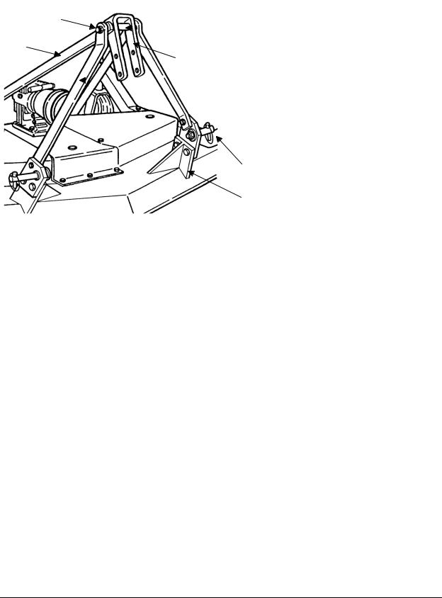
Fig. 2 |
5 |
|
|
|
1. inner spacer |
|
|
|
|
|
||
|
2 |
|
2. top hitch plate |
||
|
|
|
|||
|
|
|
3. top hitch support |
||
|
|
|
|
3 |
|
|
|
|
|
4. bolt |
|
|
|
|
|
||
|
|
|
|
|
|
|
|
|
|
|
5. top hitch arm |
|
|
|
|
|
6. linking plate |
|
|
|
|
|
7. front support plate |
|
|
|
|
|
6 |
|
|
|
|
|
7 |
|
|
|
|
|
|
To assemble the mower proceed as follows:
1.Unbolt the wheel arms and discard the mounting bracket.
2.Separate the wheel arms and remove the hardware bag secured between them.
3.IMPORTANT: Remove the belt shields to inspect around the belt area and under the gearbox central plate to be sure the area is clear of packing material such as blocks of wood, paper, etc.
4.Bolt the wheel arm assemblies to the mower deck with the flat washer and locknuts. There is no difference between left/right or front/rear. Be sure both assemblies are securely mounted.
5.Assemble each wheel to the yokes with one M14x140 bolt and one inner bushing.
Tighten down snugly. The wheel should turn freely but have no side to side movement.
6.Replace the belt shields.
7.Bolt up the top hitch arms (see #5, fig. 2 & 3) to the outside of the rear support plates on the rear of the mower (see #8, fig. 3).
8.Bolt up the top hitch supports (see #3, fig. 2 & 3) to the inside of the linking plates
(see #6, fig. 2) that are already bolted to the outside of the front support plates (see #7, fig. 2).
9.Bolt up the top hitch plate (see #2, fig. 2 & 3) with the M16x140 bolt. It should be bolted as follows: bolt, top hitch support, top hitch arm, top hitch plate, spacer, top hitch plate, top hitch arm, top hitch support, locknut. Tighten the locknut down securely, the top hitch plate should be able to swivel 360°.
10.Grease, wheel arms, and spindles. Check the gearbox for oil. It should be approximately ½ filled.
11.Install driveline and ensure it has at least 2” from bottoming out in its shortest working position and has the minimum 6” overlap in its longest working position. Refer to Section 4.061 of this manual, if it is determined that the driveline is too long
1 |
See Section 4.06 - Driveline, for instructions on how to determine correct driveline length and |
||
|
|
|
|
GENERAL INFORMATION |
6 |
FRONTIER |
|
GROOMING MOWERS |
OPERATOR’S MANUAL |
and needs to be shortened. Contact your local dealer if it is determined that the driveline is too short for your tractor.
|
|
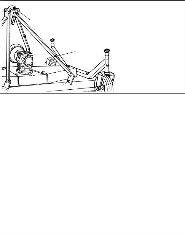
Fig. 3 |
2 |
|
2. top hitch plate |
|
3. top hitch support |
|
|
|
5. top hitch arm |
|
3 |
8. rear support plate |
|
||
5 |
|
|
8
1.05 - Quick Hitch Adapter Assembly and Operation
Using an iMatch/Quick Hitch system:
The GM1 series mowers can be used with an iMatch/Quick Hitch system, allowing for quick and easy hookup, by installing an optional adapter. This optional adapter has floating yokes that will allow the mower to follow the contour of the ground.
WARNING: When using an iMatch/Quick Hitch on a PTO driven implement always ensure there is the proper driveline overlap prior to use. If there is not the minimum 6” overlap do not use and contact your nearest dealer to purchase a longer driveline.
iMatch/Quick Hitch Adapter assembly (see fig. 4):
1.Remove hitch pins from grooming mower’s linking plates.
2.Remove M16x140 bolt on top of the three point hitch of the grooming mower.
3.Remove M20x45 bolts that hold the top hitch supports to the linking plates of the mower.
4.Attach the floating yokes of quick hitch adapter assembly to the linking plates of the mower. Note: Two ½” long bushings for the floating yokes are provided in the hardware bag of the quick hitch adapter kit. Ensure these spacers are installed onto the M16x60 bolt.
procedures for shortening the driveline.
GENERAL INFORMATION |
7 |
FRONTIER |
GROOMING MOWERS |
OPERATOR’S MANUAL |
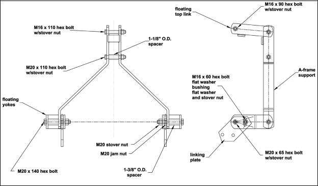
5.Attach the floating top link to the top hitch arms using the M16x90 bolt and stover nut.
6.Attach the A-frame support to the floating top link using the M16x110 bolt with stover nut.
7.Install the M20x110 bolt with the 1-1/8” spacer into the A-frame support.
8.Insert the M20x140 bolt into the floating yokes. The order should be as follows: bolt, first half of floating yoke, 1-3/8” bushing, A-frame support, M20 jam nut, second half of floating yoke, M20 stover nut. The two M20 jam nuts need to be jammed against each side of the linking plates of the grooming mower. This will allow some motion in the bushing.
9.Loosen the M16x40 bolts that secure the top hitch arms to the rear support plates of the mower. Only loosen slightly. The arms must be able to move slightly up and down.
10.Tighten all hardware, ensuring all bolts and nuts have enough play to allow quick hitch adapter to move up and down.
Fig. 4 - Quick-Hitch Adapter assembly.
iMatch/Quick Hitch adapter operation:
After completing assembly of the adapter, the tractor lift arms should be raised and locked in a position so the floating yokes are horizontal. Ensure that the M16x60 bolt is approximately in the center of the slot on the floating yoke. Positioning the bolt in this location allows the mower to have maximum float both up and down.
GENERAL INFORMATION |
8 |
FRONTIER |

GROOMING MOWERS |
OPERATOR’S MANUAL |
CAUTION: Improper setup of the quick hitch adapter can result in equipment damage. A replacement driveline must generally be installed to prevent injury or equipment damage when using the quick hitch adapter.
CAUTION: If the three point hitch of the tractor is set in the lowest position, the driveline may bottom out against the quick hitch resulting in a bent driveline. If the mower is lifted after the driveline has been bent, it may also damage the gearbox, mounting plates and other hardware.
GENERAL INFORMATION |
9 |
FRONTIER |

GROOMING MOWERS |
OPERATOR’S MANUAL |
2 - SAFETY PRECAUTIONS
Safety is the primary concern in the design and manufacture of our products. Unfortunately our efforts to provide safe equipment can be wiped out by a single careless act of an operator.
In addition to the design and configuration of equipment, hazard control and accident prevention are dependent upon the awareness, concern, prudence and proper training of personnel involved in the operation, transport, maintenance and storage of equipment. It is the operator’s responsibility to read and understand all safety and operating instructions in the manual and to follow these.
Allow only properly trained personnel to operate the mower. Working with unfamiliar equipment can lead to careless injuries. Read this manual, and the manual for your tractor, before assembly or operation, to acquaint yourself with the machines. It is the mower owner’s responsibility, if this machine is used by any person other than yourself, is loaned or rented, to make certain that the operator, prior to operating, reads and understands the operator’s manuals and is instructed in safe and proper use.
2.01- Preparation
1.Before operating equipment read and understand the operator’s manual and the safety signs (see fig. 5).
2.Thoroughly inspect the implement before initial operation to assure that all packaging materials, i.e. wires, bands, and tape have been removed.
3.Personal protection equipment including hard hat, safety glasses, safety shoes, and gloves are recommended during assembly, installation, operation, adjustment, maintaining and/or repairing the implement.
4.Operate the mower only with a tractor equipped with an approved
Roll-Over-Protective-System (ROPS). Always wear your seat belt. Serious injury or even death could result from falling off the tractor.
5.Clear area to be cut of stones, branches or other debris that might be thrown, causing injury or damage.
6.Operate only in daylight or good artificial light.
7.Ensure mower is properly mounted, adjusted and in good operating condition.
8.Ensure that all safety shielding and safety signs are properly installed and in good condition.
SAFETY PRECAUTIONS |
10 |
FRONTIER |
GROOMING MOWERS |
OPERATOR’S MANUAL |
2.02- Starting and Stopping
1.Be sure that no one is near the machine prior to engaging or while the machine is working.
2.Be sure the tractor is in “Neutral” before starting engine.
3.Mower operating power is supplied from tractor PTO. Refer to your tractor manual for PTO engagement and disengagement instructions. Always operate PTO at 540 rpm. Know how to stop the tractor and mower quickly in case of an emergency.
4.When engaging PTO, the engine rpm should always be low. Once engaged and ready to start cutting, raise PTO speed to 540 rpm and maintain throughout cutting operation.
5.Check the tractor master shield over the PTO stub shaft. Make sure it is in good condition and fastened securely to the tractor. Purchase a new shield if old shield is damaged or missing.
6.After striking an obstacle, disengage the PTO, shut the tractor down and thoroughly inspect for damage before restarting.
7.Never engage the PTO until the mower is in the down position and resting on the ground. Never raise the mower until all blades have come to a complete stop.
8.To park the vehicle safely, stop vehicle on a level surface (not on a slope), disengage PTO, engage the parking brake, stop the engine, remove the key, and wait for engine and all moving parts to stop before leaving the operator’s seat.
9.Stay clear of rotating drivelines. Entanglement in rotating driveline can cause serious injury or death. Wear close fitting clothing. Stop the engine and be sure PTO driveline is stopped before getting near it.
2.03- Messages and Signs
1.Read and adhere to all safety and operating decals on this machine (see fig. 5).
2.Before dismounting tractor: Allow moving parts to stop, stop engine, set brake and remove the key of unattended equipment.
3.Keep away from rotating blades and driveline.
4.Keep guards and shields in place and in good condition.
5.Do not mow with bystanders in area.
6.Allow no riders on tractor or mower.
7.Allow moving parts to stop before repair.
8.Securely support mower before working underneath.
Additional warning and operating decals are available at no extra charge. Please specify model and serial number when ordering.
SAFETY PRECAUTIONS |
11 |
FRONTIER |

GROOMING MOWERS |
OPERATOR’S MANUAL |
Fig. 5 - Safety decals - implement; replace immediately if damaged.
left side
placed under belt shield
right side
Red reflective decal
SAFETY PRECAUTIONS |
12 |
FRONTIER |

GROOMING MOWERS |
OPERATOR’S MANUAL |
Safety decals - driveline; replace immediately if damaged.
placed on outer shield
placed on outer tube
SAFETY PRECAUTIONS |
13 |
FRONTIER |

GROOMING MOWERS |
OPERATOR’S MANUAL |
3 - OPERATION
You have purchased a three spindle mower designed especially for the mowing of grassy areas where a highly professional cut is required without wasting time.
This mower is perfect for the maintenance of parks, private lawns, industrial parks, airports, hospital grounds, schools, highways, golf courses, sport complexes, etc. The GM1 series, for tractors up to 30 HP, come in working widths of 4’, 5’ and 6’ respectively. The mower can be either tractor front or rear mounted. On your mower, the tractor PTO transmits its power through a driveline to a speed multiplier gearbox. A pulley is attached to the pinion gear shaft of the gearbox which, via high resistance belts, transmits power to pulleys coupled to the three individual spindle shafts. Blades are secured to these shafts which turn at a high blade tip speed to cut the grass.
Our grooming mowers comes equipped with 4 swivel wheels. Aside from regulating the cutting height, the wheels are set in such a way as to allow the mower to follow the contour of the terrain and give a precise level cut even in undulating conditions.
3.01 - Operational Safety
CAUTION: Our mowers are designed considering safety as the most important aspect and are the safest available in today’s market. Unfortunately, human carelessness can override the safety features built into our machines. Injury prevention and work safety, aside from the features on our mowers, are very much due to the responsible use of the equipment. It must always be operated prudently following with great care, the safety instructions laid out in this manual.
1.The use of this equipment is subject to certain hazards which cannot be prevented by mechanical means or product design. All operators of this equipment must read and understand this entire manual, paying particular attention to safety and operating instructions, prior to using.
2.Do not operate the tractor and mower when you are tired, sick or when using medication.
3.Keep all helpers and bystanders at least several feet from a rotary mower. Only properly trained people should operate this machine.
4.The majority of accidents involve entanglements on the driveline, injury of bystanders by objects thrown by the rotating blades, and operators being knocked off the tractor by low hanging limbs and then being run over by the mower. Accidents are most likely to occur with machines that are loaned or rented to someone who has not read the operator’s manual and is not familiar with a rotary mower.
OPERATION |
14 |
FRONTIER |

GROOMING MOWERS |
OPERATOR’S MANUAL |
5.Always stop the tractor, set brake, shut off the tractor engine, remove the ignition key, lower implement to the ground and allow mower blades to come to a complete stop before dismounting tractor. Never leave equipment unattended with the tractor running.
6.Never place hands or feet under mower with tractor engine running or before you are sure all motion has stopped. Stay clear of all moving parts.
7.Do not allow riders on the mower or tractor at any time. There is no safe place for riders.
8.Do not operate unless all personnel, livestock and pets are several feet away to prevent injury by thrown objects.
9.Before backing up, disengage the mower and look behind carefully.
10.Install and secure all guards and shields before starting or operating.
11.Keep hands, feet, hair and clothing away from moving parts.
12.This rotary mower is designed for use only on tractors with 540 rpm power take off.
13.Never operate tractor and mower under trees with low hanging limbs. Operators can be knocked off the tractor and then run over by the rotating blades.
14.The rotating parts of this machine have been designed and tested for rugged use. However, they could fail upon impact with heavy, solid objects such as steel guard rails and concrete abutments. Such impact could cause the broken objects to be thrown outward at very high velocities. To reduce the possibility of property damage, serious injury, or even death, never allow the cutting blades to contact such obstacles.
15.Frequently check mower blades. They should be sharp, free of nicks and cracks and securely fastened.
16.Stop mower immediately upon striking an obstruction. Turn engine off, remove key, inspect and repair any damage before resuming operation.
17.Stay alert for holes, rocks and roots in the terrain and other hidden hazards. Keep away from drop-offs.
18.Use extreme care and maintain minimum ground speed when transporting on hillside, over rough ground and when operating close to ditches or fences. Be careful when turning sharp corners.
19.Reduce speed on slopes and sharp turns to minimize tipping or loss of control. Be careful when changing directions on slopes. Do not start or stop suddenly on slopes.
Avoid operation on steep slopes.
20.When using a unit, a minimum 20% of tractor and equipment weight must be on tractor front wheels. Without this weight, tractor could tip over, causing personal injury or death. The weight may be attained with a front end loader, front wheel weights, ballast in tires or front tractor weights. When attaining a minimum 20% of tractor and equipment weight on the front wheels, you must not exceed the ROPS weight certification. Weigh the tractor and equipment. Do not guess or estimate!
21.Inspect the entire machine periodically2. Look for loose fasteners, worn or broken parts, and leaky or loose fittings.
22.Use only the driveline supplied with the mower. Do not use it if it is missing any shield or safety protection.
2 |
See Chapter 4 - Maintenance. |
|
|
|
|
|
|
OPERATION |
15 |
FRONTIER |
|

GROOMING MOWERS |
OPERATOR’S MANUAL |
23.Pass diagonally through sharp dips and avoid sharp drops to prevent “hanging up” tractor and mower.
24.Avoid sudden starts and stops while traveling up or downhill.
25.Always cut down slopes; never across the face. Avoid operation on steep slopes. Slow down on sharp turns and slopes to prevent tipping and/or loss of control.
3.02 - Set Up
Notice to dealer: Pre-delivery setup and service including lubrication is the responsibility of the authorized dealer. It is up to him to assure that the machine is in perfect condition and ready to be used. It is his responsibility to ensure that the customer is aware of all safety aspects and operational procedures for the mower. He must also fill out the Pre-Delivery Checklist3 prior to delivering the mower.
Fig. 6
Front mount mower.
Fig. 7
Rear mount mower.
3 |
See Chapter 7 - Pre-Delivery Checklist. |
|
|
|
|
|
|
OPERATION |
16 |
FRONTIER |
|
GROOMING MOWERS |
OPERATOR’S MANUAL |
As mentioned above, all our grooming mowers may be either tractor front or rear mounted. Changing our mowers from front mount to rear, or vice versa, can be easily done at our authorized dealerships. This is accomplished by simply turning the three point hitch and the gearbox 180 degrees (see fig. 6 & 7).
3.03 - Cutting Height Adjustment
WARNING: Keep hands and feet away from moving blades.
Be sure tractor engine is off, parking brake is locked, and key is removed before making any adjustments.
Never rely on the tractor lift system. Install blocks or stands under the mower deck to prevent it from falling.
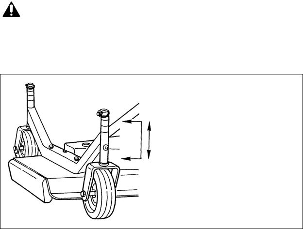
Fig. 8
The cutting height is adjusted by moving the height adjustment spacers on the wheel yokes above or below the wheel arm.
The cutting height is the distance from the blades to the ground. The cutting height is adjusted by moving the spacers on the wheel yokes. Placing spacers between the wheel arm and the wheel yoke raises the cutting height by the size of the spacer.
Removing the spacers, lowers it by the same height (see fig. 8).
Be sure all wheel arms are adjusted equally. This is the only way to ensure a completely uniform cut.
IMPORTANT: Very low cutting heights should be avoided. Damaging shock loads occur when the blades strike the ground repeatedly. This can cause damage to the mower.
OPERATION |
17 |
FRONTIER |

GROOMING MOWERS |
OPERATOR’S MANUAL |
Cutting lower than 2” under most circumstances should be avoided.
The cutting height is adjustable from 1” to 4”.
A front anti-scalp roller is also available upon request. This accessory is particularly helpful when cutting over uneven terrain.
3.04 - Pre-Operational Check
IMPORTANT: Check each of the following, carefully, prior to engaging the equipment:
1.The spindle bearings have been greased.
2.The belts for proper tension.
3.The oil in the gearbox.
4.The driveline cross and bearings have been greased.
5.No wrappings or foreign objects are around the blades, belts or driveline.
6.The blades are properly installed and the blade bolts properly torqued4.
7.All hardware is tight.
8.The tractor, to ensure correct direction of PTO and rpm speed.
9.All safety shields and guards are in place and tightly attached.
10.No people or animals are in the work area.
11.When working, make sure the tractor hitch is in the “float” position, in order to allow the mower to follow the contour of the ground.
DANGER: Stay clear of rotating driveline. Entanglement in rotating driveline can cause serious injury. Disengage PTO, engage parking brake or place transmission in “Park”, shut off the tractor and remove the key before working around hitch, attaching or detaching driveline, making adjustments, servicing or cleaning the machine.
3.05 - Attaching to the Tractor
Unit may be used on tractors ranging from 18 to 30 HP equipped with a standard PTO and category 1 three point hitch5. Never use this mower with tractors over 30 HP.
CAUTION: Check the tractor PTO rpm to ensure it is set at 540 and turns clockwise.
4
5
See Table 1, page 32. See Table 2, page 32.
OPERATION |
18 |
FRONTIER |
 Loading...