


O P E R A T O R ’ S M A N U A L
GROOMING MOWERS
FM1012
FM1015
FM1017
REAR DISCHARGE
Serial Number 1XFFM10XAB0000106 & Above
5WPMAN0862 (Rev. 10/30/2012)

TO THE DEALER:
Assembly and proper installation of this product is the responsibility of the Frontier dealer. Read manual instructions and safety rules. Make sure all items on the Dealer’s Pre-Delivery and Delivery Check Lists in the Operator’s Manual are completed before releasing equipment to the owner.
TO THE OWNER:
Read this manual before operating your Frontier equipment. The information presented will prepare you to do a better and safer job. Keep this manual handy for ready reference. Require all operators to read this manual carefully and become acquainted with all the adjustment and operating procedures before attempting to operate. Replacement manuals can be obtained from your selling dealer.
The equipment you have purchased has been carefully engineered and manufactured to provide dependable and satisfactory use. Like all mechanical products, it will require cleaning and upkeep. Lubricate the unit as specified. Observe all safety information in this manual and safety decals on the equipment.
For service, your authorized Frontier dealer has trained mechanics, genuine Frontier service parts, and the necessary tools and equipment to handle all your needs.
Use only genuine Frontier service parts. Substitute parts will void the warranty and may not meet standards required for safe and satisfactory operation. Record the model number and serial number of your equipment in the spaces provided:
Model: ______________________________ |
Date of Purchase: _____________________ |
Serial Number: (see Safety Decal section for location) ____________________________________
Provide this information to your dealer to obtain correct repair parts.
Throughout this manual, the term NOTICE is used to indicate that failure to observe can cause damage to equipment. The terms CAUTION, WARNING and DANGER are used in conjunction with the Safety-Alert Symbol, (a triangle with an exclamation mark), to indicate the degree of hazard for items of personal safety.
2 Introduction
Frontier (Rev. 12/5/2011)

TABLE OF CONTENTS
INTRODUCTION . . . . . . . . . . . . . . . . . . . . . . . . . . . . . . . . . . . . . . . . . . . . . . 2
SPECIFICATIONS. . . . . . . . . . . . . . . . . . . . . . . . . . . . . . . . . . . . . . . . . . . . . 3
GENERAL INFORMATION . . . . . . . . . . . . . . . . . . . . . . . . . . . . . . . . . . . . . . 4
SAFETY RULES . . . . . . . . . . . . . . . . . . . . . . . . . . . . . . . . . . . . . . . . . . . . . . 5
SAFETY DECALS . . . . . . . . . . . . . . . . . . . . . . . . . . . . . . . . . . . . . . . . . . . . . 9
OPERATION . . . . . . . . . . . . . . . . . . . . . . . . . . . . . . . . . . . . . . . . . . . . . . . . 13
OWNER SERVICE . . . . . . . . . . . . . . . . . . . . . . . . . . . . . . . . . . . . . . . . . . . 19
TROUBLESHOOTING . . . . . . . . . . . . . . . . . . . . . . . . . . . . . . . . . . . . . . . . 25
DEALER SERVICE . . . . . . . . . . . . . . . . . . . . . . . . . . . . . . . . . . . . . . . . . . . 27
ASSEMBLY . . . . . . . . . . . . . . . . . . . . . . . . . . . . . . . . . . . . . . . . . . . . . . . . . 34
PARTS LISTS . . . . . . . . . . . . . . . . . . . . . . . . . . . . . . . . . . . . . . . . . . . . . . . 39
BOLT TORQUE CHART . . . . . . . . . . . . . . . . . . . . . . . . . . . . . . . . . . . . . . . 61
BOLT SIZE CHART & ABBREVIATIONS . . . . . . . . . . . . . . . . . . . . . . . . . . 62
INDEX . . . . . . . . . . . . . . . . . . . . . . . . . . . . . . . . . . . . . . . . . . . . . . . . . . . . . 63
!LEA EL INSTRUCTIVO!
Si no lee Ingles, pida ayuda a alguien que si lo lea para que le traduzca las medidas de seguridad.
SPECIFICATIONS
MODEL |
FM1012 |
FM1015 |
FM1017 |
|
|
|
|
Cutting Width |
12’ |
15’ |
17’ |
|
|
|
|
Cutting Height Range |
1.0” - 5.0” |
1.0” - 5.0” |
1.0” - 5.0” |
|
|
|
|
Shipping Weight (Approximately) |
3,010 lbs. |
3,300 lbs. |
3,450 lbs. |
|
|
|
|
Blade Speed (feet per minute) |
18,000 |
18,000 |
18,000 |
|
|
|
|
Blade Spindles |
7 |
9 |
9 |
|
|
|
|
Number of Blades |
7 |
9 |
9 |
|
|
|
|
Universal Drive Series |
(Input: ASAE Cat 4; Wing: ASAE Cat 3) |
||
|
|
|
|
Transport Wheels |
20.5” x 8.0” - 10 |
20.5” x 8.0” - 10 |
20.5” x 8.0” - 10 |
|
|
|
|
Caster Wheels |
15” x 6.00” - 6 |
18” x 9.50” - 8 |
18” x 9.50” - 8 |
|
|
|
|
Tractor PTO Speed |
540 rpm |
540 rpm |
540 rpm |
|
|
|
|
Recommended Minimum |
|
|
|
Tractor Horsepower |
30 hp |
35 hp |
40 hp |
|
|
|
|
5WPMAN0862 (11/22/2010) |
Introduction 3 |
|
|

GENERAL INFORMATION

■ Some illustrations in this manual show the mower with safety shields removed to provide a better view. The mower should never be operated with any safety shielding removed.
The purpose of this manual is to assist you in operating and maintaining your Flex Wing Mower. Read it carefully. It furnishes information and instructions that will help you achieve years of dependable performance. These instructions have been compiled from extensive field experience and engineering data. Some information may be general in nature, due to unknown and varying operating conditions. However, through experi-
ence and these instructions, you should be able to develop procedures suitable to your particular situation.
The illustrations and data used in this manual were current at the time of printing. However, due to possible inline production changes, your machine may vary slightly in detail. We reserve the right to redesign and change the machines as may be necessary without notification.
Throughout this manual, references are made to right and left direction. These are determined by standing behind the tractor facing the direction of forward travel. Blade rotation is clockwise as viewed from the top of the mower.
NOTES
4 Introduction |
5WPMAN0862 (11/22/2010) |
|
|

SAFETY RULES
ATTENTION! BECOME ALERT! YOUR SAFETY IS INVOLVED!
Safety is a primary concern in the design and manufacture of our products. Unfortunately, our efforts to provide safe equipment can be wiped out by an operator’s single careless act.
In addition to the design and configuration of equipment, hazard control and accident prevention are dependent upon the awareness, concern, judgement, and proper training of personnel involved in the operation, transport, maintenance and storage of equipment.
It has been said “The best safety device is an informed, careful operator.” We ask you to be that kind of operator.
TRAINING
Safety instructions are important! Read all attachment and power unit manuals; follow all safety rules and safety decal information. (Replacement manuals and safety decals are available from your dealer.) Failure to follow instructions or safety rules can result in serious injury or death.
If you do not understand any part of this manual and need assistance, see your dealer.
Know your controls and how to stop engine and attachment quickly in an emergency.
Operators must be instructed in and be capable of the safe operation of the equipment, its attachments, and all controls. Do not allow anyone to operate this equipment without proper instructions.
Keep hands and body away from pressurized lines. Use paper or cardboard, not hands or other body parts to check for leaks. Wear safety goggles. Hydraulic fluid under pressure can easily penetrate skin and will cause serious injury or death.
Make sure that all operating and service personnel know that if hydraulic fluid penetrates skin, it must be surgically removed as soon as possible by a doctor familiar with this form of injury or gangrene, serious injury, or death will result. CONTACT A PHYSICIAN IMMEDIATELY IF FLUID ENTERS SKIN OR EYES. DO NOT DELAY.
Never allow children or untrained persons to operate equipment.
PREPARATION
Check that all hardware is properly installed. Always tighten to torque chart specifications unless instructed otherwise in this manual.
Air in hydraulic systems can cause erratic operation and allows loads or equipment components to drop unexpectedly. When connecting equipment or hoses or performing any hydraulic maintenance, purge any air in hydraulic system by operating all hydraulic functions several times. Do this before putting into service or allowing anyone to approach the equipment.
Make sure all hydraulic hoses, fittings, and valves are in good condition and not leaking before starting power unit or using equipment. Check and route hoses carefully to prevent damage. Hoses must not be twisted, bent sharply, kinked, frayed, pinched, or come into contact with any moving parts. Operate moveable components through full operational range to check clearances. Replace any damaged hoses immediately.
Always wear relatively tight and belted clothing to avoid entanglement in moving parts. Wear sturdy, rough-soled work shoes and protective equipment for eyes, hair, hands, hearing, and head; and respirator or filter mask where appropriate.
When attaching a pull-type unit to the tractor drawbar, always use a high-strength drawbar pin. The drawbar pin must have a device that will lock it into position. Secure safety chain to attachment and tractor.
Make sure attachment is properly secured, adjusted, and in good operating condition.
Make sure spring-activated locking pin or collar slides freely and is seated firmly in tractor PTO spline groove.
If equipped with driveline guard tether chains, make sure they are attached to the tractor and equipment as shown in the pamphlet that accompanies the driveline. Replace if damaged or broken. Check that driveline guards rotate freely on driveline before putting equipment into service.
Before starting the power unit, check all equipment driveline guards for damage. Replace any damaged guards. Make sure all guards rotate freely on all drivelines. If guards do not rotate freely on drivelines, repair and replace bearings before putting equipment into service.
(Safety Rules continued on next page)
Frontier FM (Rev. 1/31/2007)
Safety 5

SAFETY RULES
ATTENTION! BECOME ALERT! YOUR SAFETY IS INVOLVED!
(Safety Rules continued from previous page)
Power unit must be equipped with ROPS or ROPS cab and seat belt. Keep seat belt securely fastened. Falling off power unit can result in death from being run over or crushed. Keep foldable ROPS systems in “locked up” position at all times.
Inspect chain shielding before each use. Replace if damaged.
Remove accumulated debris from this equipment, power unit, and engine to avoid fire hazard.
Make sure all safety decals are installed. Replace if damaged. (See Safety Decals section for location.)
Make sure shields and guards are properly installed and in good condition. Replace if damaged.
A minimum 20% of tractor and equipment weight must be on the tractor front wheels when attachments are in transport position. Without this weight, tractor could tip over, causing personal injury or death. The weight may be attained with front wheel weights, ballast in tires or front tractor weights. Weigh the tractor and equipment. Do not estimate.
Inspect and clear area of stones, branches, or other hard objects that might be thrown, causing injury or damage.
Never attach the mower release rope to the operator, the operator's clothing, or the tractor seat.
Make test turns, both left and right. Check that both the hydraulic hose and the mower transport lock release rope do not become taut or caught on any parts of the tractor or mower.
TRANSPORTATION
The maximum transport speed for towed and semi-mounted machines is 20 mph (32 km/h). Regardless of the maximum speed capability of the towing tractor, do not exceed the implement’s maximum transport speed. Doing so could result in:
•Loss of control of the implement and tractor
•Reduced or no ability to stop during braking
•Implement tire failure
•Damage to the implement or its components.
Use additional caution and reduce speed when under adverse surface conditions, turning, or on inclines.
Do not operate PTO during transport.
Never tow this implement with a motor vehicle.
OPERATION
Only engage power when equipment is at ground operating level. Always disengage power when equipment is raised off the ground.
Do not allow bystanders in the area when operating, attaching, removing, assembling, or servicing equipment.
Never walk, stand, or place yourself or others under a raised wing or in the path of a lowering wing. Hydraulic system leak-down, hydraulic system failures, mechanical failures, or movement of control levers can cause wings to drop unexpectedly and cause severe injury or death.
Full chain shielding must be installed when operating in populated areas or other areas where thrown objects could injure people or damage property.
•If this machine is not equipped with full chain shielding, operation must be stopped when anyone comes within 300 feet (92 m).
•This shielding is designed to reduce the risk of thrown objects. The mower deck and protective devices cannot prevent all objects from escaping the blade enclosure in every mowing condition. It is possible for objects to ricochet and escape, traveling as much as 300 feet (92 m).
Never direct discharge toward people, animals, or property.
Do not operate or transport equipment while under the influence of alcohol or drugs.
Operate only in daylight or good artificial light.
Keep hands, feet, hair, and clothing away from equipment while engine is running. Stay clear of all moving parts.
Always comply with all state and local lighting and marking requirements.
Never allow riders on power unit or attachment.
Power unit must be equipped with ROPS or ROPS cab and seat belt. Keep seat belt securely fastened. Falling off power unit can result in death from being run over or crushed. Keep foldable ROPS systems in “locked up” position at all times.
(Safety Rules continued on next page)
6 Safety
Frontier FM (Rev. 1/31/2007)

SAFETY RULES
ATTENTION! BECOME ALERT! YOUR SAFETY IS INVOLVED!
(Safety Rules continued from previous page)
Always sit in power unit seat when operating controls or starting engine. Securely fasten seat belt, place transmission in neutral, engage brake, and ensure all other controls are disengaged before starting power unit engine.
Operate tractor PTO at 540 RPM. Do not exceed.
Do not operate mowers on terrain that raises mowers beyond 25 degrees. Exceeding this design limit will result in U-joint “knocking noise” and potential driveline failure and could cause driveline to pull apart.
Before raising or lowering wings, front hitch/lift and rear wheel/lift cylinders must be fully extended and all four cylinder locks installed. This prevents rotor and bearing support damage that can result from ground contact.
Look down and to the rear and make sure area is clear before operating in reverse.
Do not operate or transport on steep slopes.
Do not stop, start, or change directions suddenly on slopes.
Use extreme care and reduce ground speed on slopes and rough terrain.
Watch for hidden hazards on the terrain during operation.
Stop power unit and implement immediately upon striking an obstruction. Dismount power unit, using proper procedure. Inspect and repair any damage before resuming operation.
Always connect safety chain from equipment to towing vehicle when transporting.
MAINTENANCE
Before dismounting power unit or performing any service or maintenance, follow these steps: disengage power to equipment, lower the 3-point hitch and all raised components to the ground, operate valve levers to release any hydraulic pressure, set parking brake, stop engine, remove key, and unfasten seat belt.
Before working underneath, carefully read Operator’s Manual instructions, disconnect driveline, raise mower, securely block up all corners with jackstands, and check stability. Secure blocking prevents equipment from dropping due to hydraulic leak down, hydraulic system failures, or mechanical component failures.
Do not modify or alter or permit anyone else to modify or alter the equipment or any of its components in any way.
Your dealer can supply original equipment hydraulic accessories and repair parts. Substitute parts may not meet original equipment specifications and may be dangerous.
To prevent contamination, clean and then cover hose ends, fittings, and motor ports with tape.
Always wear relatively tight and belted clothing to avoid entanglement in moving parts. Wear sturdy, rough-soled work shoes and protective equipment for eyes, hair, hands, hearing, and head; and respirator or filter mask where appropriate.
Do not allow bystanders in the area when operating, attaching, removing, assembling, or servicing equipment.
Make sure attachment is properly secured, adjusted, and in good operating condition.
Keep all persons away from operator control area while performing adjustments, service, or maintenance.
Frequently check blades. They should be sharp, free of nicks and cracks, and securely fastened.
Do not handle blades with bare hands. Careless or improper handling may result in serious injury.
Your dealer can supply genuine replacement blades. Substitute blades may not meet original equipment specifications and may be dangerous.
Tighten all bolts, nuts and screws to torque chart specifications. Check that all cotter pins are installed securely to ensure equipment is in a safe condition before putting unit into service.
Make sure all safety decals are installed. Replace if damaged. (See Safety Decals section for location.)
Make sure shields and guards are properly installed and in good condition. Replace if damaged.
Do not disconnect hydraulic lines until engine is stopped, power unit is properly secured, equipment and all components are lowered to the ground, and system pressure is released by operating all valve control levers.
(Safety Rules continued on next page)
Frontier FM (Rev. 1/31/2007)
Safety 7

SAFETY RULES
ATTENTION! BECOME ALERT! YOUR SAFETY IS INVOLVED!
(Safety Rules continued from previous page)
When lubricating telescoping PTO drives, keep fingers out of shield access slots to prevent injury.
Wear gloves when installing belt. Be careful to prevent fingers from being caught between belt and pulley.
Use care when installing or removing belt from spring-loaded idler. Springs store energy when
extended and, if released suddenly, can cause personal injury.
STORAGE
Block equipment securely for storage.
Keep children and bystanders away from storage area.
8 Safety
Frontier FM (Rev. 1/31/2007)
SAFETY & INSTRUCTIONAL DECALS
ATTENTION! BECOME ALERT! YOUR SAFETY IS INVOLVED!
Replace Immediately If Damaged!
1 -5WP18867
 DANGER
SHIELD MISSING
DO NOT OPERATE
PUT SHIELD ON
18867--B
5 - Serial Number Plate
PRODUCT IDENTIFICATION NUMBER |
LENEXA, KS, U.S.A. |
2 - 5WP15503 |
 DANGER
ROTATING BLADES AND
THROWN OBJECTS
Do not put hands or feet under or into mower when engine is running.
Before mowing, clear area of objects that may be thrown by blade.
Keep bystanders away.
Keep guards in place and in good condition.
BLADE CONTACT OR THROWN OBJECTS CAN CAUSE SERIOUS INJURY OR DEATH.
15503-C
FM1015 & FM1017 REAR DECK (FM1012 SIMILAR)
BE CAREFUL!
Use a clean, damp cloth to clean safety decals.
Avoid spraying too close to decals when using a pressure washer; high-pressure water can enter through very small scratches or under edges of decals causing them to peel or come off.
Replacement safety decals can be ordered free from your dealer.
8 - 5WP18866


 WARNING
540 RPM
! " #$
18866-D
5WPMAN0862 (11/22/2010) |
Safety 9 |
|
|

SAFETY & INSTRUCTIONAL DECALS
ATTENTION! BECOME ALERT! YOUR SAFETY IS INVOLVED!
Replace Immediately If Damaged!
16 - 5WP38446
WING DECK
IMPORTANT
OPERATING MOWERS AT RAISED ANGLES EXCEEDING 25•
WILL CREATE U-JOINT KNOCKING NOISE AND DAMAGE
DRIVELINE. FAILURES RESULTING FROM THIS OPERATION
WILL NOT BE COVERED BY WARRANTY. |
38446 |
13 - 5WP1002940 YELLOW FRONT REFLECTOR
12 - 5WP18869
 DANGER
SHIELD MISSING
18869
3 - 5WP18864
 DANGER
ROTATING DRIVELINE
CONTACT CAN CAUSE DEATH
KEEP AWAY!
DO NOT OPERATE WITHOUT-
ALL DRIVELINE GUARDS, TRACTOR AND EQUIPMENT SHIELDS IN PLACE
DRIVELINES SECURELY ATTACHED AT BOTH ENDS
DRIVELINE GUARDS THAT TURN FREELY
ON DRIVELINE |
18864B |
|
9 - 5WP18865


 WARNING
FALLING OFF CAN RESULT IN BEING RUN OVER.
Tractor must be equipped with ROPS (or ROPS CAB) and seat belt. Keep foldable ROPS systems in “locked up” position at all times.
Buckle Up! Keep seat belt securely fastened.
Allow no riders.
RAISED EQUIPMENT CAN DROP AND CRUSH.
Before working underneath, follow all instructions and safety rules in operator’s manual and securely block up all corners of equipment with jack stands.
Securely blocking prevents equipment dropping from hydraulic leakdown, hydraulic system failures or mechanical component failures.
FALLING OFF OR FAILING TO BLOCK SECURELY CAN RESULT IN SERIOUS INJURY OR DEATH.
10 Safety |
5WPMAN0862 (11/22/2010) |
|
|
SAFETY & INSTRUCTIONAL DECALS
ATTENTION! BECOME ALERT! YOUR SAFETY IS INVOLVED!
Replace Immediately If Damaged!


 WARNING
RAISED MOWER CAN DROP AND CRUSH
Before working underneath rear mower:Raise rear mower to transport position.
Insert pin to lock transport latch.
Securely block up rear of mower. See manual.
Blocking up prevents mower dropping from transport latch release or failure, hydraulic leak down, or hydraulic system failures.
FAILURE TO FOLLOW INSTRUCTIONS CAN 44650 RESULT IN SERIOUS INJURY OR DEATH.
PIN STORAGE
POSITION
PIN INSERTED TO LOCK TRANSPORT LATCH
7 - 5WP44650 |
|
|
|
11 - 5WP44651 |
WARNING |
|
|
|
TO LOCK |
PIN |
|
|
|
PIN INSERTED |
STORAGE |
|
|
TRANSPORT |
POSITION |
|
RAISED MOWERS CAN |
|
|
|
LATCH |
|
|
|
DROP AND CRUSH |
|
|
|
Keep away. Do not go underneath. |
|
|
|
When raised, insert pins to lock transport latches. |
|
|
|
Lower after transport. |
|
|
|
FAILURE TO FOLLOW INSTRUCTIONS CAN |
|
|
44651 |
RESULT IN SERIOUS INJURY OR DEATH. |
|
|
4 - 5WP33347


33347E


6 - 5WP38421


 WARNING
RAISED MOWER CAN
DROP AND CRUSH
1Before working underneath side mowers, lower side mowers and securely block up. See manual.
1Blocking up prevents mower dropping from transport latch release or failure, hydraulic leak down or hydraulic system failure.
|
FAILURE TO FOLLOW INSTRUCTIONS CAN |
38421-A |
RESULT IN SERIOUS INJURY OR DEATH. |
|
17 - 5WP44656
WARNING
RAISED MOWERS EXPOSE
BLADES AND INCREASE
THROWN OBJECT HAZARDS
|
Only raise for transport. |
|
Stop mowers before raising. |
|
FAILURE TO FOLLOW INSTRUCTIONS CAN |
44656 |
RESULT IN SERIOUS INJURY OR DEATH. |
5WPMAN0862 (11/22/2010) |
Safety 11 |
|
|
SAFETY & INSTRUCTIONAL DECALS
ATTENTION! BECOME ALERT! YOUR SAFETY IS INVOLVED!
Replace Immediately If Damaged!
FM1015, FM1017, &
FM1012 TRAILER
18 - 5WP1002941
 WARNING
CRUSHING AND PINCHING HAZARD
Be extremely careful handling various parts of the machine. They are heavy and hands, fingers, feet, and other body parts could be crushed or pinched between tractor and implement.
Operate tractor controls from tractor seat only.
Do not stand between tractor and implement when tractor is in gear.
Make sure parking brake is engaged before going between tractor and implement.
Stand clear of machine while in operation or when it is being raised or lowered.
FAILURE TO FOLLOW THESE INSTRUCTIONS COULD RESULT IN SERIOUS INJURY
OR DEATH.
1002941-A
 WARNING
TO AVOID SERIOUS INJURY OR DEATH:
Read Operator's Manual (available from dealer) and follow all safety precautions.
Keep all shields in place and in good condition.
Operate mower from tractor seat only.
Lower mower, stop engine and remove key before dismounting tractor.
Allow no children or untrained persons to operate equipment.
Do not transport towed or semi-mounted units over 20 mph.
FAILURE TO OPERATE SAFELY
CAN RESULT IN
INJURY OR DEATH.
18877-C
14 - 5WP57123 RED REAR REFLECTOR
10 - 5WP18877
15 - 5WP19924
WARNING
Check for leaks with cardboard; never use hand.
Before loosening fittings: lower load, release pressure, and be sure oil is cool.
Consult physician immediately if skin penetration occurs.
12 Safety |
5WPMAN0862 (11/22/2010) |
|
|

OPERATION
The operator is responsible for the safe operation of the cutter. The operator must be properly trained. Operators should be familiar with the cutter, the tractor, and all safety practices before starting operation. Read the safety rules and safety decals on page 5 through page 12.
This mower is designed for lawn and grass mowing. It is not designed for rough conditions or heavy weed mowing. It is equipped with suction type blades for best results in lawn mowing.
Recommended mowing speed for most conditions is from 2 to 5 mph. Always operate power unit PTO at 540 rpm.
This section provides information for attaching the mower to the tractor and preparing it for field operation. Review this data prior to tractor hook-up and operation.
Lower mower to the ground when not in use.

Full chain shielding must be installed when operating in populated areas or other areas where thrown objects could injure people or damage property.
•If this machine is not equipped with full chain shielding, operation must be stopped when anyone comes within 300 feet (92 m).
•This shielding is designed to reduce the risk of thrown objects. The mower deck and protective devices cannot prevent all objects from escaping the blade enclosure in every mowing condition. It is possible for objects to ricochet and escape, traveling as much as 300 feet (92 m).

Before dismounting power unit or performing any service or maintenance, follow these steps: disengage power to equipment, lower the 3-point hitch and all raised components to the ground, operate valve levers to release any hydraulic pressure, set parking brake, stop engine, remove key, and unfasten seat belt.
Never allow riders on power unit or attachment.
Never allow children or untrained persons to operate equipment.

Keep bystanders away from equipment.
Make sure spring-activated locking pin or collar slides freely and is seated firmly in tractor PTO spline groove.
Operate tractor PTO at 540 RPM. Do not exceed.
 CAUTION
Stop power unit and implement immediately upon striking an obstruction. Dismount power unit, using proper procedure. Inspect and repair any damage before resuming operation.
Always wear relatively tight and belted clothing to avoid getting caught in moving parts. Wear sturdy, rough-soled work shoes and protective equipment for eyes, hair, hands, hearing, and head; and respirator or filter mask where appropriate.
ATTACHING MOWER TO TRACTOR

Make sure spring-activated locking pin or collar slides freely and is seated firmly in tractor PTO spline groove.
Make sure shields and guards are properly installed and in good condition. Replace if damaged.
Never attach the mower release rope to the operator, the operator's clothing, or the tractor seat.
1.Park mower and tractor on a level, hard-surfaced area.
2.Adjust tractor hitch bracket on trailer frame so the trailer is level when attached to the tractor. Pin the mower to the tractor.
NOTE: When attaching mower to tractor drawbar, make sure the correct drawbar pin is used. A Category 1 drawbar is 1"; Category 2 is 1.25". Failure to use the correct pin size will result in premature wear of hitch and drawbar hole. If the hitch on the mower doesn't match your tractor drawbar, contact your dealer to order the correct size hitch for your tractor. If mower will be attached to tractor for a long period of time, secure hitch to drawbar using a bolt, locknut, and washers assembled tightly. This will reduce wear on drawbar and hitch.
A 1-3/8" 6B spline PTO shaft is used for connecting the mower to the tractor. This mower is designed for 540 rpm PTO only.
5WPMAN0862 (11/11/2010) |
Operation 13 |
|
|
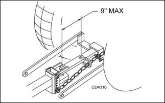
The PTO drive shaft is intended for use with tractors that have 14 inches between the end of the PTO shaft and the tractor's drawbar hitch pin hole.
3.Attach the safety chain to the tractor as shown in Figure 1.
4.Attach the mower drive shaft to tractor PTO. Make sure the lock collar engages securely.
5.Attach the end of the mower’s transport lock release rope to a location on the tractor within easy reach of the operator.
NOTE: When routing the rope, do not route through the hydraulic hose guide and do not allow rope slack to drop between the driveline shields and the gearbox rotating shafts.
Figure 1. Tow Chain Installation
Attaching Hydraulic Hoses
1.Attach the hydraulic hose from the mower to the tractor.
2.Route the hose through the hose guide of the trailer frame and be sure the hose can slide freely in the guide. Do not allow hose slack to drag on the ground or become caught on tractor protrusions.
3.From the operator position, start the tractor, raise and lower the wings, and the rear deck several times. This will purge the hydraulic cylinders and hoses of trapped air.
Interference Check
1.Be sure that the tractor 3-point arms do not interfere with hydraulic hoses, driveline or mower frame.
2.Check for straight ahead operation and full turning angles. If there is any interference, remove the 3- point arms.
NOTE: Contact between 3-point arms and mower can cause damage, especially when turning.
CV Driveline Turning Limits
NOTICE
■ Do not exceed turning angle of 80 degrees at the head of the Constant Velocity (CV) driveline or damage will occur.
Check for excessive turn angle:
1.Disconnect the driveline from the tractor.
2.Start engine and turn as far right or left as possible.
3.Shut off the engine and connect the CV driveline to the tractor. If it cannot be connected, the turn angle is too severe.
4.Restart the tractor and straighten the angle slightly.
5.Shut off the engine and connect the CV driveline to tractor.
6.Repeat the process until the driveline can be connected. The point at which the driveline can be connected is the maximum turn that can be made.
Leveling Mower
NOTE: To ensure satisfactory mower performance, the trailer frame and decks must be leveled before operating the mower. During normal operation, the mower should be leveled twice each season. The mower must be leveled each time a tractor with a different drawbar height is used.
Follow this procedure to level the mower for operation:
1.Park the tractor and mower on a flat level surface with the decks in mowing position.
2.Inflate all tires to the recommended pressure: 70 psi for trailer tires and 30 psi for deck gauge tires.
3.Level the trailer frame by adjusting the hitch. (See Figure 2.)
4.Remove the hitch clevis from the trailer frame and pin to the tractor drawbar.
5.Use the parking jack to adjust the trailer frame to the level position. Align the nearest hitch adjustment hole in the hitch clevis with a hole in the trailer frame.
6.Tighten the hardware to specifications in the Bolt Torque Chart on page 61. Readjust the level of the frame each time the drawbar height changes.
7.Attach the mower and the driveline to the tractor. Level the driveline by placing a bolt through the carrier bearing and the driveline height adjustment holes.
14 Operation |
5WPMAN0862 (11/22/2010) |
|
|
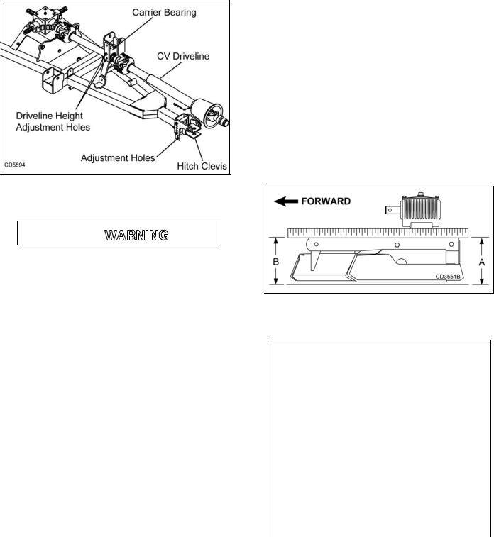
Figure 2. Level Trailer Frame
CUTTING HEIGHT ADJUSTMENT

Keep all persons away from operator control area while performing adjustments, service, or maintenance.
Before working underneath, carefully read Operator’s Manual instructions, disconnect driveline, raise mower, securely block up all corners with jackstands, and check stability. Secure blocking prevents equipment from dropping due to hydraulic leak down, hydraulic system failures, or mechanical component failures.
NOTICE
■ Avoid low cutting heights. Striking the ground with blades produces one of the most damaging shock loads a mower can encounter. Allowing blades to contact ground repeatedly will cause damage to mower and drive.
1.Level mower from side to side. Check by measuring from mower frame to the ground at each deck rail.
2.Verify that the same amount of spacers are under all caster arms.
3.Loosen cap screws that attach caster arm assembly to deck.
4.Set mower on the ground.
5.Retighten cap screws. This equalizes the clearance in the bolt holes.
6.Best mowing results will be obtained with front of mower level with, or slightly lower than, the rear.
7.Cutting height is controlled with front and rear caster wheel adjustment.
8.To raise rear of mower, move caster adjustment spacers under caster arms.
9.To raise front of mower, move spacers under front caster wheel arms.
Remember, measurement at location A (Figure 3) should not be less than location B and should not be over 1/2" greater than location B
Figure 3. Cutting Height Adjustment
Table 1: Cutting Height Chart
Spacers Required Under
Caster Arm Pivot Tube
Cut |
1/2" |
3/4" |
1 |
Height |
Spacer |
Spacer |
Spacer |
|
|
|
|
1" |
|
|
|
|
|
|
|
1-1/2" |
1 |
|
|
|
|
|
|
2" |
|
|
1 |
|
|
|
|
2-1/2" |
1 |
|
1 |
|
|
|
|
3" |
|
|
2 |
|
|
|
|
3-1/2" |
1 |
|
2 |
|
|
|
|
4" |
1 |
2 |
1 |
|
|
|
|
4-1/2" |
|
2 |
2 |
|
|
|
|
5" |
1 |
2 |
2 |
|
|
|
|
5WPMAN0862 (11/11/2010) |
Operation 15 |
|
|
TRANSPORT
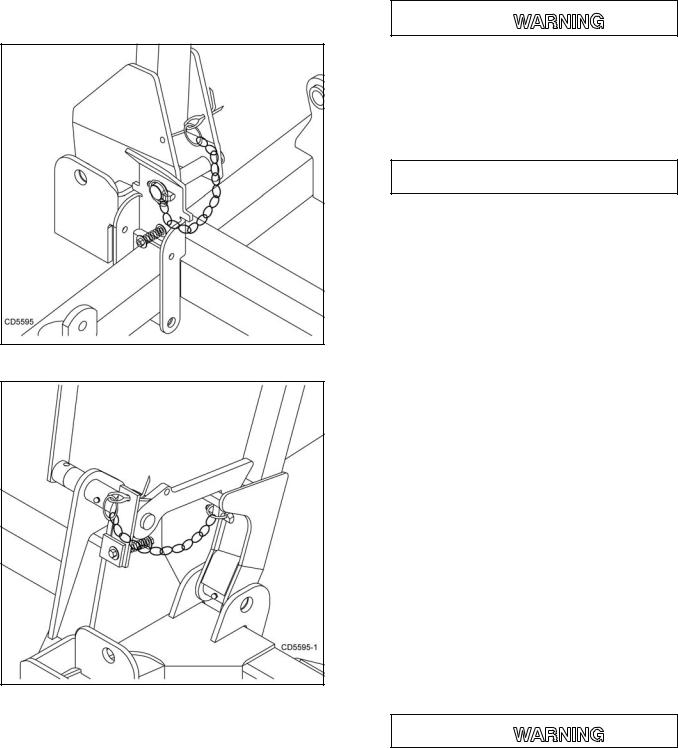
When transporting the mower short distances, raise the wings and the rear deck until all three transport locks engage automatically.
Install locking pins to secure the mower wings for transport as shown in Figure 4 and Figure 5.
Figure 4. Lock Pin Installed (Right Wing)
Figure 5. Lock Pin Storage Installed
(Rear Deck)
To lower the wings and the rear deck:
1.Remove the locking pins and store in holes provided.
2.Slightly raise the wings and rear deck to take pressure off the locking mechanisms.
3.Pull the transport lock release rope to disengage the locks. Lower the wings and rear deck and release the rope.
STARTING AND STOPPING MOWER

Do not operate PTO during transport.
Never direct discharge toward people, animals, or property.
Keep hands, feet, hair, and clothing away from equipment while engine is running. Stay clear of all moving parts.
 CAUTION
Stop power unit and implement immediately upon striking an obstruction. Dismount power unit, using proper procedure. Inspect and repair any damage before resuming operation.
Always sit in power unit seat when operating controls or starting engine. Securely fasten seat belt, place transmission in neutral, engage brake, and ensure all other controls are disengaged before starting power unit engine.
NOTICE
■ Stopping the mower with belt in contact with a very hot pulley will bake and ruin belt.
Power for operating the mower is supplied from the tractor PTO. Refer to your tractor manual for instructions on engaging and disengaging the PTO.
Operate PTO at 540 rpm. Know how to stop tractor and mower quickly in case of an emergency.
If the mower becomes plugged causing the belt to slip for over two seconds, follow these steps:
1.Raise mower just enough to clear accumulated material.
2.Continue running at least two minutes, allowing pulleys to cool.
To reduce the risk of thrown objects, do not raise the mower higher than necessary
OPERATING

Do not operate mowers on terrain that raises mowers beyond 25 degrees. Exceeding this design limit will result in U-joint “knocking noise” and potential driveline failure and could cause driveline to pull apart.
16 Operation |
5WPMAN0862 (11/22/2010) |
|
|

When engaging the PTO, engine rpm should always be low. Once engaged and ready for mowing, increase PTO speed to 540 rpm and maintain speed throughout the cutting operation.
Mower vibration tends to loosen bolts. All hardware should be checked regularly to maintain proper torque. Each time the mower is used, check all hardware to be sure it is secure. Recommended torque values can be found on page 61.
The condition of the terrain will determine cutting results. For best results, mower blades should be kept sharp at all times and the platform as level as possible. When mower blades show excessive wear, they should be replaced.
Operating Technique
 CAUTION
Stop power unit and implement immediately upon striking an obstruction. Dismount power unit, using proper procedure. Inspect and repair any damage before resuming operation.
Proper ground speed will depend upon the terrain, the height, type, and density of material to be cut.
Normally, ground speed will range from two to five mph. Tall dense material should be cut at a low speed; thin medium-height material can be cut at a faster ground speed.
Always operate tractor PTO at 540 rpm to maintain proper blade speed and produce a clean cut.
Under certain conditions, tractor tires may roll some grass down and prevent it from being cut at the same height as the surrounding area. When this occurs, reduce your ground speed, but maintain PTO at 540 rpm. The lower ground speed will permit grass to partially rebound.
In general, lower cutting heights give a more even cut with less tendency to leave tire tracks. However, it is better to cut grass frequently rather than too short. Short grass deteriorates rapidly in hot weather and invites weed growth during growing seasons. Follow local recommendations for the suitable cutting height in your area.
Operating Tips

Inspect and clear area of stones, branches, or other hard objects that might be thrown, causing injury or damage.
Extremely tall material should be cut twice. Set mower at a higher cutting height for the first pass. Then cut at desired height 90 degrees to the first pass.
Remember, sharp blades produce cleaner cuts and require less power.
Analyze area to be cut to determine the best procedure. Consider height and type of grass and terrain type: hilly, level, or rough.
Uneven Terrain

Do not operate or transport on steep slopes.
Do not stop, start, or change directions suddenly on slopes.
Use extreme care and reduce ground speed on slopes and rough terrain.
Watch for hidden hazards on the terrain during operation.
In extremely uneven terrain, rear wheel weights, front tractor weights and/or front tire ballast should be used to improve stability.
Pass diagonally through sharp dips and avoid sharp drops to prevent “hanging up” the tractor and the mower. Practice will improve your skills in maneuvering rough terrain.
Avoid sudden starts and stops when traveling up or down hill.
Always mow down slopes, never up or across the face. Avoid operating on steep slopes.
Slow down on sharp turns and slopes to prevent tipping and losing control.
REMOVING MOWER FROM TRACTOR
1.Park the unit on a level, hard surface with the wings and rear deck fully lowered to the ground.
2.Block the wheels to keep the mower from rolling when unhitched from tractor.
3.Attach the jack to the side of the tongue and adjust the height to take the weight off the tractor hitch.
4.Disconnect the PTO shaft and the hydraulic hose, untie the mower transport lock release rope from the tractor, and remove the hitch pin.
5.Store the PTO shaft end and the hydraulic hose couplings off the ground and keep them clean.
5WPMAN0862 (11/11/2010) |
Operation 17 |
|
|

PRE-OPERATION CHECK LIST |
NOTES |
(OWNER's RESPONSIBILITY)
___ |
Review and follow all safety rules and safety |
|
decal instructions on pages 5 through 12. |
___ |
Check that all safety decals are installed and in |
|
good condition. Replace if damaged. |
___ |
Check that all shields and guards are properly |
|
installed and in good condition. Replace if dam- |
|
aged. |
___ |
Check that chain shielding is in good condition |
|
and replace any damaged chain links. |
___ |
Check that all hardware and cotter pins are prop- |
|
erly installed and secured. |
___ |
Check to ensure blades are sharp, in good condi- |
|
tion, and installed correctly. Replace if damaged. |
___ |
Check that equipment is properly and securely |
|
attached to tractor. |
___ |
Make sure driveline spring-activated locking pin |
|
or collar slides freely and is seated firmly in trac- |
|
tor PTO spline groove. |
___ |
Make sure the driveline guards and tether chains |
|
are in good condition. Guards must rotate freely |
|
on driveline. Fasten tether chains as instructed to |
|
the tractor and the equipment. |
___ |
Inspect area and remove stones, branches or |
|
other hard objects that might be thrown, causing |
|
injury or damage. |
___ |
Do not allow riders. |
___ Check all lubrication points and grease as instructed in Lubrication Information, page 20. Make sure the PTO slip joint is lubricated and that the gearbox fluid levels are correct.
___ Check that all hydraulic hoses and fittings are in good condition and not leaking before starting tractor. Check that hoses are not twisted, bent sharply, kinked, frayed or pulled tight. Replace any damaged hoses immediately.
___ Make sure tractor ROPS or ROPS cab and seat belt are in good condition. Keep seat belt securely fastened during operation.
___ Before starting engine, operator must be in tractor seat with seat belt fastened. Place transmission in neutral or park, engage brake and disengage tractor PTO.
18 Operation |
5WPMAN0862 (11/22/2010) |
|
|
OWNER SERVICE
The information in this section is written for operators who possess basic mechanical skills. If you need help, your dealer has trained service technicians available. For your protection, read and follow the safety information in this manual

Full chain shielding must be installed when operating in populated areas or other areas where thrown objects could injure people or damage property.
•If this machine is not equipped with full chain shielding, operation must be stopped when anyone comes within 300 feet (92 m).
•This shielding is designed to reduce the risk of thrown objects. The mower deck and protective devices cannot prevent all objects from escaping the blade enclosure in every mowing condition. It is possible for objects to ricochet and escape, traveling as much as 300 feet (92 m).

Keep hands and body away from pressurized lines. Use paper or cardboard, not hands or other body parts to check for leaks. Wear safety goggles. Hydraulic fluid under pressure can easily penetrate skin and will cause serious injury or death.
Make sure that all operating and service personnel know that if hydraulic fluid penetrates skin, it must be surgically removed as soon as possible by a doctor familiar with this form of injury or gangrene, serious injury, or death will result. CONTACT A PHYSICIAN IMMEDIATELY IF FLUID ENTERS SKIN OR EYES. DO NOT DELAY.
Keep all persons away from operator control area while performing adjustments, service, or maintenance.
Do not disconnect hydraulic lines until engine is stopped, power unit is properly secured, equipment and all components are lowered to the ground, and system pressure is released by operating all valve control levers.
Before dismounting power unit or performing any service or maintenance, follow these steps: disengage power to equipment, lower the 3-point hitch and all raised components to the ground, operate valve levers to release any hydraulic pressure, set parking brake, stop engine, remove key, and unfasten seat belt.
 CAUTION
Always wear relatively tight and belted clothing to avoid getting caught in moving parts. Wear sturdy, rough-soled work shoes and protective equipment for eyes, hair, hands, hearing, and head; and respirator or filter mask where appropriate.
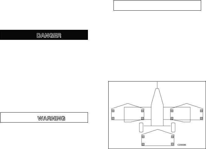
BLOCKING METHOD
The only approved blocking devices for this mower are jack stands with a load rating of 1,000 pounds or more. Twelve jack stands, located as shown in Figure 6, must be installed before working underneath this unit.
Figure 6. Jackstand Placement
Do not work underneath mower unless it is properly attached to tractor and blocked securely. When properly attached, the unit will be anchored to minimize front to rear movement.
Before blocking, be sure that the mower is securely attached to the tractor. Lower mower units to the ground. Raise the mower units as needed for working room and securely block them. Set tractor brakes, turn engine off and remove key, then disconnect mower driveline.
When blocking, you must consider the overall stability of the unit. Just placing jackstands under the unit will not ensure your safety. The working surface must be level and solid to support the loaded weight of the jack stands. Ensure that jackstands are stable at both top and bottom. Before working under any portion of the mower, test the stability of your blocking with the full weight of the mower units lowered onto the jackstands.
5WPMAN0862 (11/22/2010) |
Owner Service 19 |
|
|
LUBRICATION INFORMATION
 CAUTION
When lubricating telescoping PTO drives, keep fingers out of shield access slots to prevent injury.
Do not let excess grease collect on or around parts, particularly when operating in sandy areas.
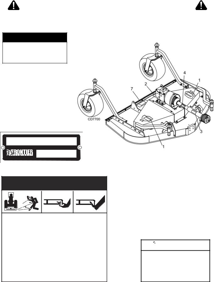
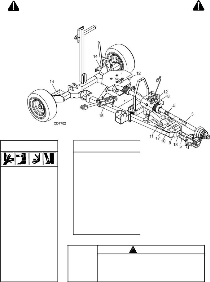
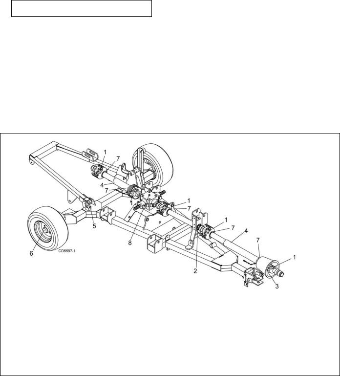
Figure 7 and Figure 8 shows lubrication points. The accompanying charts give the frequency of lubrication in operating hours, based on normal operating conditions. Severe or unusual conditions may require more frequent lubrication.
Use a lithium grease of #2 consistency with a MOLY (molybdenum disulfide) additive for all locations unless otherwise noted.
Be sure to clean fittings thoroughly before attaching grease gun. When applied according to the lubrication chart, one good pump of most guns is sufficient. Use SAE 90W gear lube in gearboxes.
Daily lubrication of PTO slip joints is necessary. Failure to maintain proper lubrication can result in damage to U-joints, gearboxes and/or drive shafts. Raise or lower mower until grease fittings in PTO shields are exposed. Insert grease gun through slots and apply grease to all sides of shafts. Always stand clear of mower and wing arm mechanism to avoid being pinched or crushed should the mower or wing suddenly lower.
Raise and lower mower after applying grease so that it spreads over the slip joint working area.
REF |
DESCRIPTION |
FREQUENCY |
1 |
Driveline U-Joint |
8 Hours |
2 |
Drive Carrier Bearing |
8 Hours |
3 |
CV Body |
8 Hours |
4 |
Telescoping Shaft |
8 Hours |
5 |
Rear Deck Pivot Arm |
8 Hours |
6 |
Transport Wheel Hub |
8 Hours |
7 |
Shield Bearing |
8 Hours |
8 |
Splitter Gearbox (Fill 1/2 |
Check For Leaks Daily |
|
full w/SAE 90W gear lube) |
|
Figure 7. Lubrication Points - Trailer
20 Owner Service |
5WPMAN0862 (11/22/2010) |
|
|
 Loading...