


AC-G3010H, AC-G4010H ,
AC-G4010S and AC-G5010S
Generators
Operator’s Manual |
|

Introduction
THANK YOU for purchasing a John Deere product.
READ THIS MANUAL carefully to learn how to operate and service your machine correctly. Failure to do so could result in personal injury or equipment damage. This manual and safety signs on your machine may also be available in other languages. (See your John Deere dealer to order.)
THIS MANUAL SHOULD BE CONSIDERED a permanent part of your machine and should remain with the machine when you sell it.
MEASUREMENTS in this manual are given in both metric and customary U.S. unit equivalents. Use only correct replacement parts and fasteners. Metric and inch fasteners may require a specific metric or inch wrench.
RIGHT HAND AND LEFT HAND sides are determined by facing the motor end of the machine.
The SERIAL NUMBER is located in the Specification or Identification Numbers section. Accurately record all the numbers to help in tracing the machine should it be stolen. Your dealer also needs these numbers when you order parts. File the identification numbers in a secure place off the machine.
WARRANTY is provided from your John Deere dealer for customers who operate and maintain their equipment as described in this manual. The warranty is explained on the warranty certificate shown in this manual.
This warranty provides you the assurance that your dealer will back products where defects appear within the warranty period. Should the equipment be abused, or modified to change its performance beyond the original factory specifications, the warranty will become void.
|
|
Operator’s Manual |
|
||
|

|
Contents |
|
Page |
Safety ......................................................................... |
4 |
Safety Signs .............................................................. |
5 |
Controls .................................................................. |
12 |
Preparing the Generator ........................................ |
13 |
Operation ................................................................. |
17 |
Troubleshooting ..................................................... |
21 |
Service ..................................................................... |
22 |
Storage .................................................................... |
27 |
Specifications ......................................................... |
28 |
Accessoires.............................................................. |
29 |
Warranty .............................................................. |
30-32 |
All information, illustrations and specifications in this manual are based on the latest information available at the time of publication. The right is reserved to make changes at any time without notice.
Operator’s Manual |
|
Safety
Recognize safety information
This is the safety alert symbol. When you see this symbol on your machine or in this manual, be alert to the potential for personal injury.
Follow recommended precautions and safe operating practices.
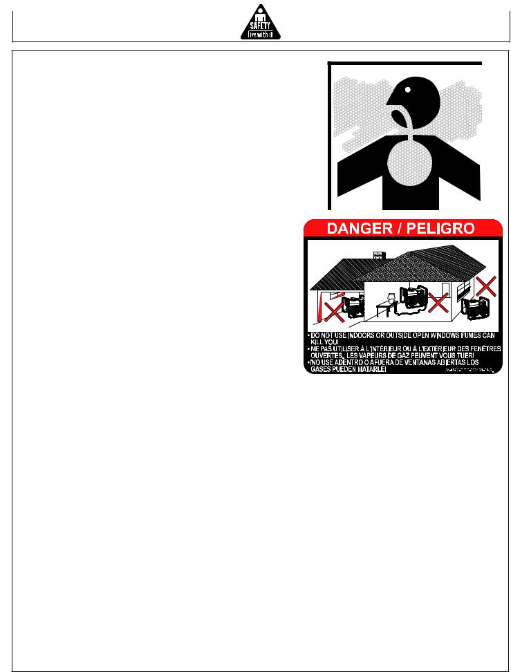
understand signal words
A signal word--DANGER, WARNING or CAUTION--is used with the safety-alert symbol. DANGER identifies the most serious hazards.
DANGER or WARNING safety signs are located near specific hazards. General precautions are listed on CAUTION safety signs. CAUTION also calls attention to safety messages in this manual.
follow safety instructions
Carefully read all safety messages in this manual and safety signs on your machine. Keep safety signs in good condition. Replace missing or damaged safety signs. Be sure new equipment components and repair parts include the current safety signs. Replacement safety signs are available from your John Deere customer service representative.
Learn how to operate the machine and how to use controls properly. Do not let anyone operate without instruction.
Keep your machine in proper working condition.
Unauthorized modifications to the machine may impair the function and/or safety and affect machine life.
If you do not understand any part of this manual and need assistance, contact your John Deere customer service representative.
|
|
|
|
|
|
G |
|
|
|
|
IN |
||
|
|
|
N |
|
|
|
|
R |
|
|
|
||
A |
|
|
|
|
|
|
W |
|
|
|
SIN |
||
|
|
ING |
|
. |
||
|
RN |
|
|
LS |
||
A |
|
|
UA |
|
||
W |
|
AN |
|
IN |
||
|
EM |
|
GS |
|||
TH |
|
|
S. |
|||
|
|
NIN |
|
|||
|
AR |
|
|
AL |
||
W |
|
|
NU |
|
||
THE |
MA |
|
|
|||
|
|
|
|
|
||
|
|
|
|
|
|
|
|
|
N |
|
|
|
|
|
|
|
|
|
|
U |
IO |
ON |
|
|
|||||
|
|
|
|
A |
T |
|
TI |
|
SIN |
|||||
|
|
|
|
|
|
|
|
|
|
S |
||||
|
|
|
C |
|
|
|
AU |
|
|
|
AL |
|||
|
|
|
|
|
|
|
OC |
|
|
NU |
|
|||
|
|
|
|
IN |
|
|
HE |
MA |
|
SIN |
||||
|
|
|
NS |
|
|
|
|
|
UT |
|
|
|
LS |
|
|
|
TIO |
|
LS |
O |
CA |
|
|
|
UA |
||||
AU |
|
|
|
|
|
AN |
|
|||||||
OC |
|
|
NUA |
|
|
|
EM |
|
|
|
||||
HEMA NSIN |
OTH |
|
|
|
|
|
||||||||
OT |
|
TIO |
|
|
S |
|
|
|
|
|
|
|
|
|
|
AU |
|
|
AL |
|
|
|
|
|
|
|
|
||
OC |
|
NU |
|
|
|
|
|
|
|
|
|
|||
|
HE |
MA |
|
|
|
|
|
|
|
|
|
|
|
|
OT |
|
|
|
|
|
|
|
|
|
|
|
|
|
|
Operator’s Manual
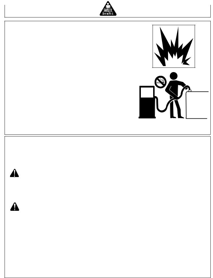
carbon monoxide - POISONOUS GAS
Use generator outdoors, away from open windows, vents, or doors.
Generator exhaust contains carbon monoxide - a poisonous gas that can kill you. You CAN NOT smell or see this gas.
Never use a generator in enclosed or partially-enclosed spaces. Generators can produce high levels of carbon monoxide very quickly. When you use a portable generator, remember that you cannot smell or see carbon monoxide. Even if you can’t smell exhaust fumes, you may still be exposed to carbon monoxide.
If you start to feel sick, dizzy, or weak while using a generator, get to fresh air RIGHT AWAY. DO NOT DELAY. The carbon monoxide from generators can rapidly lead to full incapacitation and death.
If you experience serious symptoms, get medical attention immediately. Inform medical staff that carbon monoxide poisoning is suspected. If you experienced symptoms while indoors, have someone call the fire department to determine when it is safe to re-enter the building.
Never operate the generator in an explosive atmosphere, near combustible materials or where ventilation is not sufficient to carry away exhaust fumes. Exhaust fumes can cause serious injury or death.
NEVER use a generator indoors, including in homes, garages, basements, crawl spaces, and other enclosed or partially-enclosed areas, even with ventilation. Opening doors and windows or using fans will not prevent carbon monoxide build-up in the home.
Follow the instructions that come with your generator. Locate the unit outdoors and away from doors, windows, and vents that could allow the carbon monoxide gas to come indoors.
ONLY run generator outdoors and away from air intakes.
NEVER run generator inside homes, garages, sheds, or other semi-enclosed spaces. These spaces can trap poisonous gases EVEN IF you run a fan or open doors and windows.
If you start to feel sick, dizzy, or weak while using the generator, shut if off and get fresh air RIGHT AWAY. See a doctor. You may have carbon monoxide poisoning.
Install battery-operated carbon monoxide alarms or plug-in carbon monoxide alarms with battery back-up in your home, according to the manufacturer’s installation instructions. The carbon monoxide alarms should be certified to the requirements of the latest safety standards for carbon monoxide alarms. (UL 2034, IAS 6-96, or CSA 6.19.01).
Test your carbon monoxide alarm frequently and replace dead batteries.
Operator’s Manual
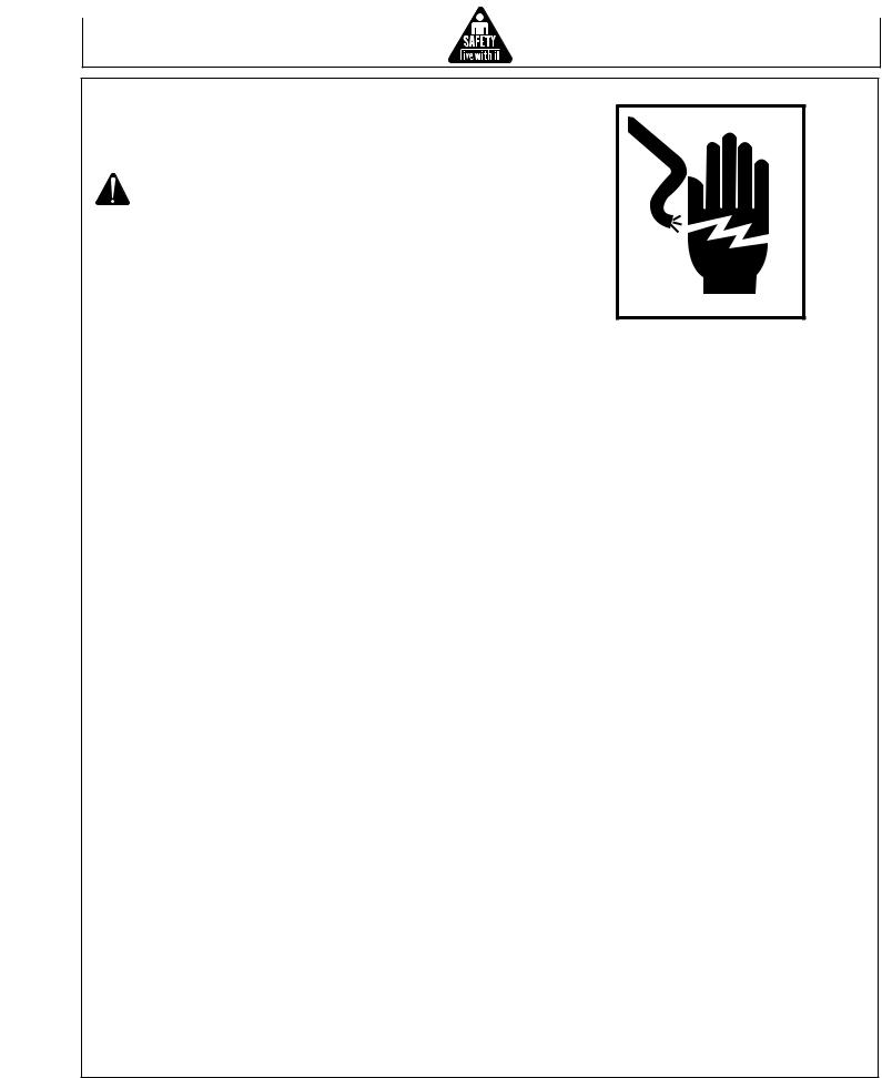
SAFETY WARNING WHEN REFUELING
Gasoline is extremely flammable and its vapors can explode if ignited.
Observe all safety regulations for the safe handling of fuel. Handle fuel in safety containers. If the container does not have a spout, use a funnel.
Do not overfill the fuel tank, leave room for the fuel to expand.
Do not refill fuel tank while the engine is running. Before refueling the generator, turn it off and let it cool down. Gasoline spilled on hot engine parts could ignite.
Fill the tank only on an area of bare ground. While fueling the tank, keep heat, sparks and open flame away. Carefully clean up any spilled fuel before starting engine.
Always fill fuel tank in an area with plenty of ventilation to avoid inhaling dangerous fumes.
NEVER store fuel for your generator in the home. Gasoline, propane, kerosene, and other flammable liquids should be stored outside of living areas in properly-labeled, non-glass safety containers. Do not store them near a fuel-burning appliance, such as a natural gas water heater in a garage. If the fuel is spilled or the container is not sealed properly, invisible vapors from the fuel can travel along the ground and can be ignited by the appliance’s pilot light or by arcs from electric switches in the appliance.
GROUND FAULT CIRCUIT INTERRUPTER PROTECTION
These generators are equipped with two GFCI (Ground Fault Circuit Interrupters) 120V duplex receptacles for protection against the hazards of electrical shock from defective attachments such as, tools, cords, and cables.
WARNING: The GFCIs may not function unless the generator is properly grounded. Follow the correct procedure specified in the section labeled “GROUNDING
INSTRUCTIONS”
A GFCI is a device that interrupts electricity from either the utility or generator by means of a special type of circuit breaker if a fault current flow to the ground occurs.
WARNING: Only the 120V Duplex Receptacles are protected by the GFCI.
A GFCI can be used only with generators that have the neutral wire internally bonded to the frame, and the frame properly grounded to the earth. A GFCI will not work on generators that do not have the neutral wire bonded to the frame, or on generators which have not been properly grounded. All John Deere generators have internally bonded ground wires. A GFCI will not work if the unit is not properly grounded.
A GFCI may be required by OSHA regulations, the National Electric Code and/or local and federal codes when operating a generator.
For additional protections against shock hazards due to defective equipment attached to the twist-lock receptacles, consider the use of a GFCI on each of these receptacles as well.
GFCIs and GFCI protected cord sets and cables may be purchased from local electrical supply houses.
Operator’s Manual
ELECTRICAL HAZARDS
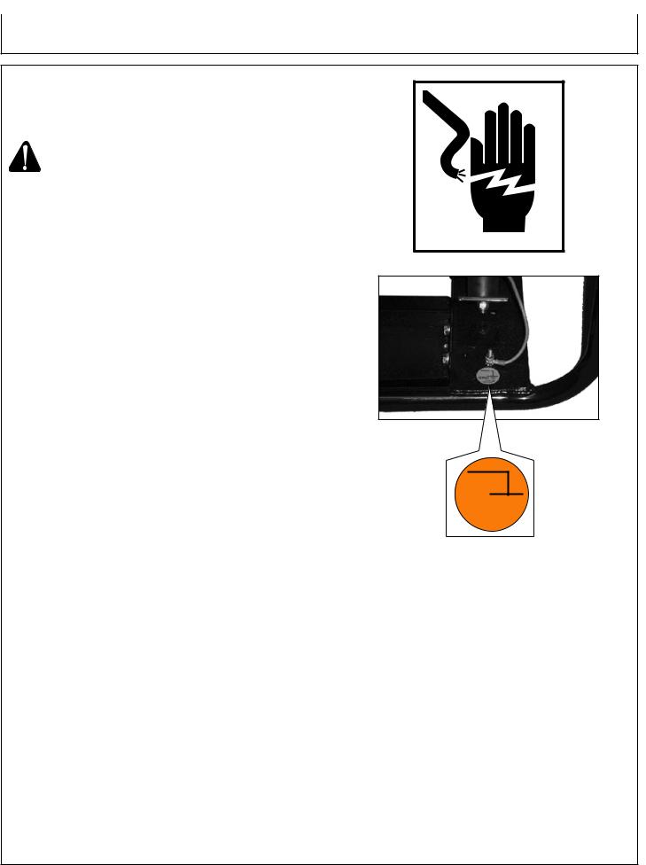
This product must be grounded. If it should malfunction or breakdown, grounding provides a path of least resistance for electric current to reduce the risk of electric shock.
DANGER - Improper connection of the equipmentgrounding conductor can result in a risk of electrocution. Check with a qualified electrician or service person if you are IN doubt as to whether the unit is properly grounded.
This generator is equipped with a grounding terminal for your protection. Always complete the ground path from the generator to an external ground source as instructed in the section labeled “Grounding Instructions” in the Preparation section of this manual.
The generator is a potential source of electrical shock if not kept dry. Keep the generator dry and do not use in rain or wet conditions. To protect from moisture, operate it on a dry surface under an open, canopy-like structure. Dry your hands if wet before touching the generator.
Risk of electric shock if you operate this generator with a faulty GFCI (Ground Fault Circuit Interrupter). Test GFCI before each use, see Operations Instructions for further information. If GFCI fails test, DO
NOT use your generator. Contact your John Deere customer service representative.
Plug appliances directly into the generator. Or, use a heavy duty, outdoor-rated extension cord that is rated (in watts or amps) at least equal to the sum of the connected appliance loads. Check that the entire cord is free of cuts or tears and that the plug has all three prongs, especially a grounding pin.
NEVER try to power the house wiring by plugging the generator into a wall outlet, a practice known as “back feeding”. This is an extremely dangerous practice that presents an electrocution risk to utility workers and neighbors served by the same utility transformer. It also bypasses some of the built-in household circuit protection devices.
If you must connect the generator to the house wiring to power appliances, have a qualified electrician install the appropriate equipment in accordance with local electrical codes. Or, check with your utility company to see if it can install an appropriate power transfer switch.
For power outages, permanently installed stationary generators are better suited for providing backup power to the home. Even a properly connected portable generator can become overloaded. This may result in overheating or stressing the generator components, possibly leading to a generator failure.
Operator’s Manual
important safety instructions
WARNING: To reduce the risk of injury, read this operator’s manual completely before using. When using this product, the following basic precautions should always be followed:
1.Read all the instructions before using the product.
2.This product is equipped with a Ground Fault Circuit Interrupter (GFCI) in the power cord to reduce the risk of electrical shock. If replacement of the plug or cord is needed, use only identical replacement parts.
3.Do not allow children or untrained persons to operate the generator.
4.Do not operate the generator when fatigued or under the influence of drugs or chemicals. Stay alert. Watch what you are doing.
5.Follow the maintenance instructions specified in this manual.
6.When starting the generator, using recoil starter grip, be sure that nothing is in a position to be hit by the operator’s hand or arm.
7.Be sure the switch on electric power tools is in the “OFF” position before plugging them into the generator.
8.Keep the immediate area free of all bystanders.
9.Be sure each person who operates this generator is properly instructed in its safe operation.
|
|
|
|
|
|
|
|
|
|
N |
|
|
|
|
|
|
|
|
|
IO |
|
IN |
|
|
|
|
|
|
|
|
UT |
|
|||
|
|
|
|
|
|
A |
|
|
|
S |
|
|
|
|
|
|
C |
|
|
CAUTIONSAL |
|||
|
|
|
|
|
|
|
|
O |
THE |
MANU |
|
|
|
|
G |
|
NSIN |
|
SIN |
||||
|
|
|
|
O |
|
UTION |
S |
||||
|
|
IN |
UTIO |
|
LS |
OCA |
UAL |
||||
RN |
|
OCA |
NUA |
|
|
EMAN |
|
||||
WA |
|
GSIN |
HEMA NSIN |
OTH |
|
|
|||||
|
|
OT UTIO |
|
S |
|
|
|
|
|||
RNIN |
S. |
OCA |
NUAL |
|
|
|
|
||||
WA |
ANUAL |
OTHE |
MA |
|
|
|
|
|
|
||
EM |
|
IN |
|
|
|
|
|
|
|
||
TH |
INGS |
. |
|
|
|
|
|
|
|
|
|
ARN |
ALS |
|
|
|
|
|
|
|
|
||
W |
MANU |
|
|
|
|
|
|
|
|
|
|
THE |
|
|
|
|
|
|
|
|
|
|
|
Operator’s Manual
important safety instructions
10.Do not operate the generator or any electrical tool in any area where water or similar materials constitute
an electrical hazard to the operator. Do not operate on wet surfaces, in rain or in snow.
11.Always be sure that the generator is on secure footing so that it cannot slide or shift around, endangering workers.
12.Avoid contacting the hot exhaust manifold, muffler or cylinder(s). Keep clear of all rotating parts.
13.Unless the tool or appliance is double insulated, it must be grounded through a properly grounded receptacle. (See Preparing the Generator, Grounding Instructions). Tools and appliances which have 3 prong plugs must be plugged into extension cords and electrical receptacles with 3 holes. Before operating any electrical item, be sure it is in good repair.
14.Follow instructions in this manual when testing Ground Fault Circuit Interrupter to insure reliable operation.
15.Beware of using this equipment in confined spaces.
Confined spaces, without sufficient fresh air ventilation, can contain dangerous gases. Running gasoline engines in such environments can lead to deadly explosions and/ or asphyxiation.
16.If your generator comes equipped with a transport dolly, make sure this unit is secure during operation and when transporting to prevent unexpected movement or rolling.
17.Use extreme caution when lifting this generator. Do not use dolly handles to lift this generator, use only designated lifting hook to lift this generator. This generator is heavy so proper lifting techniques should be used.
SAVE THESE INSTRUCTIONS
|
|
|
|
|
|
|
|
|
N |
|
|
|
|
|
|
|
|
IO |
SIN |
||
|
|
|
|
|
|
|
T |
|
||
|
|
|
|
|
|
AU |
|
|
|
N |
|
|
|
|
|
C |
O |
CAUTIO UALS |
|||
|
|
|
|
|
|
|
|
HE |
MAN |
|
|
|
|
G |
|
SIN |
OT |
TION LS |
|||
|
|
IN |
UTION |
S |
OCAU NUA |
|||||
RN |
|
OCA |
NUAL |
|
|
EMA |
||||
WA |
GSIN |
HEMA NSIN |
OTH |
|
||||||
|
OT UTIO |
LS |
|
|
|
|
||||
RNIN |
LS. |
OCA |
NUA |
|
|
|
|
|||
WA |
ANUA |
IN |
EMA |
|
|
|
|
|
||
EM |
|
OTH |
|
|
|
|
|
|
||
TH |
INGS |
. |
|
|
|
|
|
|
|
|
ARN |
ALS |
|
|
|
|
|
|
|
||
W |
MANU |
|
|
|
|
|
|
|
|
|
THE |
|
|
|
|
|
|
|
|
|
|
Operator’s Manual
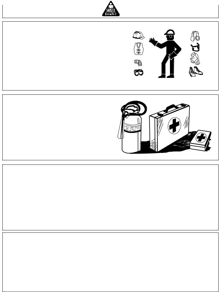
wear protective clothing
Wear close fitting clothing and safety equipment appropriate to the job.
Wear a suitable hearing protective device such as earmuffs or earplugs to protect against objectionable or uncomfortable loud noises.
Operating equipment safely requires the full attention of the operator. Do not wear radio or music headphones while operating machine.
prepare for emergencies
Keep a first aid kit and fire extinguisher handy.
Keep emergency numbers for doctors, ambulance service, hospital and fire department near your telephone.
Be prepared if a fire starts.
inspect GENERATOR
Be sure all covers, guards and shields are tight and in place.
Locate all operating controls and safety labels.
Inspect power cord for damage before using. There is a hazard of electrical shock from crushing, cutting or heat damage.
service GENERATOR safely
Before servicing the generator, disconnect all equipment and battery (if equipped) and allow unit to cool down.
Service generator in a clean dry flat area.
10 |
Operator’s Manual |

SAFETY SIGNS FOR AC-G3010H, AC-G4010H, AC-G4010S AND AC-G5010S
GND 
34-0889
062104-ENG.
34-0889
34-1677 or 34-1764
34-1680 or 34-1762
 DANGER
Using a generator indoors CAN KILL YOU IN MINUTES.
Generator exhaust contains carbon monoxide. This is a poison you cannot see or smell.
|
|
|
|
|
|
|
|
NEVER use inside a home |
Only use OUTSIDE and far |
||
or garage, EVEN IF doors |
away from windows, doors, |
||
and windows are open. |
and vents. |
||
 DANGER
L'utilisation d'un groupe électrogène à l'intérieur PEUT VOUS TUER EN QUELQUES MINUTES.
Le gaz d'échappement du groupe électrogène contient de l'oxyde de carbone. C'est un gaz toxique que l'on ne peut pas voir ou sentir.
Ne JAMAIS utiliser à l'intérieur d'une maison ou d'un garage, MÊME SI les portes et fenêtres s'ont ouvertes.
N'utiliser qu'à l'EXTÉRIEUR et bien éloigné des fenêtres, portes, et conduits d'aération.
 PELIGRO
Utilizando un generador adentro PUEDE MATARLE EN MINUTOS.
El escape de generador contiene monóxido de carbono. Este es un gas tóxico que usted no puede ver ni puede oler.
Nunca utilice dentro de un hogar ni el garaje, INCLUSO SI puertas y ventanas estén abiertas.
Solo utilice AFUERAS y lejos de ventanas abiertas, las puertas, y descargas.
34-1916
Operator’s Manual |
11 |

Controls
controls FOR AC-G3010H. AC-G4010S, AC-G4010H, AC-G5010S
B  C
C
 A
A
 D
D
 E
E
B
D
 E
E
B C
C
 A
A
 D
D
 E
E
 C
C
 A
A
A -- |
Control Panel |
C -- |
Fuel Cap |
E -- Oil Drain |
B -- |
Fuel Tank |
D-- |
Oil Dipstick |
|
12 |
Operator’s Manual |
Preparing the Generator
GROUNDING INSTRUCTIONS
This product must be grounded. If it should malfunction or breakdown, grounding provides a path of least resistance for electric current to reduce the risk of electric shock.
DANGER - Improper connection of the equipment-grounding conductor can result in a risk of electrocution. Check with a qualified electrician or service person if you are in doubt as to whether the unit is properly grounded.
The wing nut and ground terminal on the frame must always be used to connect the generator to a suitable ground source. The ground path should be made with #8 size wire. Connect the terminal of the ground wire between the two star washers and wing nut then tighten the wing nut fully. Connect the other end of the wire securely to a suitable ground source.
The National Electric Code contains several practical ways in which to establish a good ground source. Examples given below illustrate a few of the ways in which a good ground source may be established.
A metal underground water pipe in direct contact with the earth for at least 10 feet can be used as a grounding source. If an pipe is unavailable, an 8 foot length of pipe or rod may be used as the ground source. The pipe should be 3/4 inch trade size or larger and the outer surface must be noncorrosive. If a steel or iron rod is used it should be at least 5/8 inch diameter and if a nonferrous rod is used it should be at least 1/2 inch diameter and be listed as material for grounding. Drive the rod or pipe to a depth of 8 feet. If a rock bottom is encountered less than 4 feet down, bury the rod or pipe in a trench. All electrical tools and appliances operated from this generator, must be properly grounded by use of a third wire or be “Double Insulated”.
It is recommended to:
1.Use electrical devices with 3 prong power cords.
2.Use an extension cord with a 3 hole receptacle and a 3 prong plug at the opposite ends to ensure continuity of the ground protection from the generator to appliance.
We strongly recommend that all applicable federal, state and local regulations relating to grounding specifications be checked and followed.
LINE TRANSFER SWITCH
If this generator is used for standby service, it must have a transfer switch between the utility power service and the generator. The transfer switch not only prevents the utility
power form feeding into the generator, but is also prevents the generator form feeding out into the utility company’s lines. This is intended to protect the serviceman who may be working on a damaged line.
THIS INSTALLATION MUST BE DONE BY A LICENSED ELECTRICIAN AND ALL LOCAL CODES MUST BE FOLLOWED.
GND 
34-0889
062104-ENG.
Operator’s Manual |
13 |
Preparing the Generator
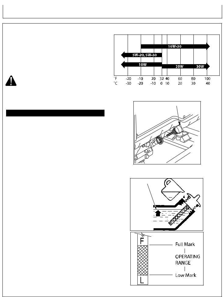
engine oil
TEMPERATURE CHART
Use oil viscosity based on the expected air temperature range during the period between oil changes.
Use a high quality detergent oil with API classifications of
SJ or higher.
Check oil level before each operation and ensure that it is maintained.
CAUTION: THIS ENGINE CRANKCASE IS NOT
FILLED WITH OIL AT THE FACTORY, SO BE
SURE TO FILL IT BEFORE OPERATING THE
ENGINE.
ENGINE OIL CAPACITY
MODEL # |
Liters |
Quart |
Ounces |
AC-G3010H |
0.6 |
0.63 |
20.3 |
AC-G4010S |
0.6 |
0.63 |
20.3 |
AC-G4010H |
1.1 |
1.16 |
37.2 |
AC-G5010S |
1.1 |
1.16 |
37.2 |
NOTE: These engines are equipped with a “Low Oil” shut-off system for engine protection. If the engine fails to start, check engine crankcase for oil.
To fill with oil:
1.Level the engine to ensure accurate inspection and to prevent overfilling.
2.Unscrew the oil gauge (Fig. 1), wipe the dipstick dry.
Reinsert the oil gauge back into the oil fill gauge opening.
Remove the oil gauge and check the oil level.
3.The oil level should be between the full and low marks on the dipstick. (Fig. 2)
NOTE: When checking the oil be sure the engine is level.
4.Fill with oil as required through the oil fill gauge opening.
5.Replace the oil gauge and screw in firmly.
6.Wipe up any spilled oil.
OIL GAUGE |
(Fig. 1)
UPPER LEVEL
(Fig. 2)
14 |
Operator’s Manual |

Preparing the Generator
FUELING
WARNING: EXPLOSIVE FUEL!
GASOLINE IS EXTREMELY FLAMMABLE AND ITS VAPORS CAN EXPLODE IF IGNITED.
STORE GASOLINE ONLY IN APPROVED
CONTAINERS, IN WELL VENTILATED,
UNOCCUPIED BUILDINGS AND AWAY
FROM SPARKS OR FLAMES.
DO NOT FILL THE FUEL TANK WHILE THE
ENGINE IS HOT OR RUNNING, SINCE
SPILLED FUEL COULD IGNITE IF IT
COMES IN CONTACT WITH HOT PARTS OR
SPARKS FROM IGNITION. DO NOT START
THE ENGINE NEAR SPILLED FUEL.
NEVER USE GASOLINE AS A CLEANING
AGENT.
WARNING: DO NOT OVERFILL THE FUEL TANK,
LEAVE ROOM FOR THE FUEL TO EXPAND.
General Recommendations
•Purchase gasoline in small quantities and store in clean, approved containers.
•To minimize gum deposits in your fuel system and to insure easy starting, do not use gasoline left over from the previous season.
•Do not add oil to the gasoline.
Fuel Type
•For best results use only clean, fresh, unleaded gasoline with a pump sticker octane rating of 87 or higher.
•Unleaded gasoline is recommended as it leaves less combustion chamber deposits.
Gasoline/Alcohol Blends:
Gasohol (up to 10% ethyl alcohol, 90% unleaded gasoline by volume) is approved, as a fuel. Other gasoline/alcohol blends are not approved.
Gasoline/Ether Blends:
Methyl Tertiary Butyl Ether (MTBE) and unleaded gasoline blends (up to a maximum of 15% MTBE by volume) are approved as a fuel. Other gasoline/ether blends are not approved.
Operator’s Manual |
15 |

Preparing the Generator
HIGH ALTITUDE
At high altitude, the standard carburetor air/fuel mixture will be too rich. Performance will decrease, and fuel consumption will increase. A very rich mixture will also foul the spark plug and cause hard starting. Operation at an altitude that differs from that at which this engine was certified, for extended periods of time, may increase emissions.
High altitude performance can be improved by specific modifications to the carburetor. If you always operate your generator at altitudes above 5,000 feet (1,500 meters), have your dealer perform this carburetor modification. This engine, when operated at high altitude with the carburetor modifications for high altitude use, will meet each emission standard throughout its useful life.
Even with carburetor modification, engine horsepower will decrease about 3.5% for each 1,000-foot (300-meter) increase in altitude. The effect of altitude on horsepower will be greater than this if no carburetor modification is made.
NOTE:When the carburetor has been modified for high altitude operation, the air/fuel mixture will be too lean for low altitude use. Operation at altitudes below 5,000 feet (1,500 meters) with a modified carburetor may cause the engine to overheat and result in serious engine damage.
For use at low altitudes, have your servicing dealer return the carburetor to original factory specifications.
16 |
Operator’s Manual |
Operation
Operation
Recoil Start
NOTE: Read Operator’s Manual carefully before operating this unit. Always make sure the unit is level and properly grounded. Check engine oil before starting.
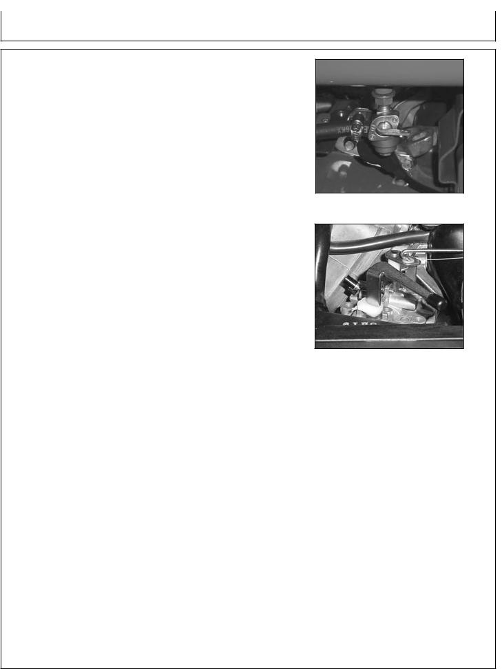
1.Open fuel valve on fuel tank. (See Fig. 3)
2.Move choke lever to full choke. If re-starting a warm engine, the choke should be left in the off position. (See Fig. 4)
3.Turn the engine ignition switch to the ON position.
4.Pull recoil to start engine.
5.Once engine has started, slowly move choke lever to no choke.
NOTE: When engine fails to start after several attempts, repeat the starting procedures mentioned above with the choke lever in the off position.
6.Allow the unit to run for two (2) minute warm-up.
7.Make sure the generator is grounded. See Preparing the Generator; Grounding Instructions.
8.Test the GFCI receptacle(s) on the unit. Push the test button. The reset button should pop out and there should be no power at the receptacle. Apply a test load or lamp to each receptacle to verify. IF THE RESET BUTTON DOES NOT POP OUT, DO NOT USE THE RECEPTACLES(S). SEE DEALER FOR SERVICE IMMEDIATELY.
9.If GFCI receptacle(s) test correctly, firmly push the reset button to restore power. A distinctive click should be heard or felt when this is complete. IF THE RECEPTACLE(S) DO NOT RESET PROPERLY, DO NOT USE THE RECEPTACLE(S). SEE DEALER FOR SERVICE IMMEDIATELY.
10.Loads can now be applied to the unit.
11.If unit is equipped with a Full Power Switch, move the Full Power Switch to the 120V position to direct all power to the 120V/30A receptacle on the unit. This will disable all other receptacles.
When the Full Power Switch is in the 120V/240V position, all receptacles are usable except the 120V/30A receptacle.
NOTE: This engine is equipped with a “Low Oil” shutdown system for engine protection. The engine stops when the oil level gets too low. The engine will not restart without adding oil. Refer to Preparing the Generator; Engine Fuel Capacity for instructions on adding oil.
(Fig. 3)
(Fig. 4) (Subaru Shown)
Operator’s Manual |
17 |

Operating the Generator
SHUTDOWN
1.Remove all load by turning off electrical appliances and unplugging electric cords.
2.Allow engine to run at idle speed or at no load condition to cool for two (2) minutes.
NOTE: Failure to allow the engine to cool for two (2) minutes may result in damage to the generator.
3.Turn engine key or ignition switch off.
4.Close fuel valve on unit or engine.
controls
CONTROL PANEL:
The generators are equipped with the following items:
AC-G3010H:
-Circuit Breaker
-One 125 Volt, 20 Amp, GFCI protected receptacles.
AC-G4010H, AC-G4010S, AC-G5010S:
-Full Power Switch
-Circuit Breakers
-Two 125 Volt, 20 Amp, Duplex (2 outlets), GFCI protected receptacles.
-One 125 Volt, 30 Amp, Locking Type Receptacle.
-One 125/250 Volt, 20 Amp, Locking Type Receptacle.
NOTE: The 125 Volt, 30 Amp locking receptacles ARE NOT GROUND FAULT PROTECTED. If ground fault protection on these receptacles is necessary or desired, external protection devices must be used. Refer to the section on “Ground Fault Interrupter” for more information.
WARNING: NEVER EXCEED THE RATING OF A RECEPTACLE. These receptacles are protected against overloads by resetting magnetic type circuit breakers. If a circuit breaker trips, the cause should be determined and corrected prior to continuing use.
18 |
Operator’s Manual |

Operating the Generator
Controls
OIL WARNING DEVICE:
NOTE: This engine is equipped with a “Low Oil” shutdown system for engine protection. The engine stops when
the oil level gets too low. The engine will not restart without adding oil. If the unit is tilted too much during operation, it may suddenly stop even though the oil level is not low.
Check the engine oil before restarting the engine. If the unit is tilted, level the engine, then check the oil before restarting the engine.
FULL POWER SWITCH:
The Full Power Switch allows the unit to suppy power directly to the 120V30A receptacle on the unit. This will disable all other receptacles.
When the Full Power Switch is in the 120V/240V position, all receptacles are usable except the 120V-30A receptacle.
Operator’s Manual |
19 |

Operating the Generator
controls
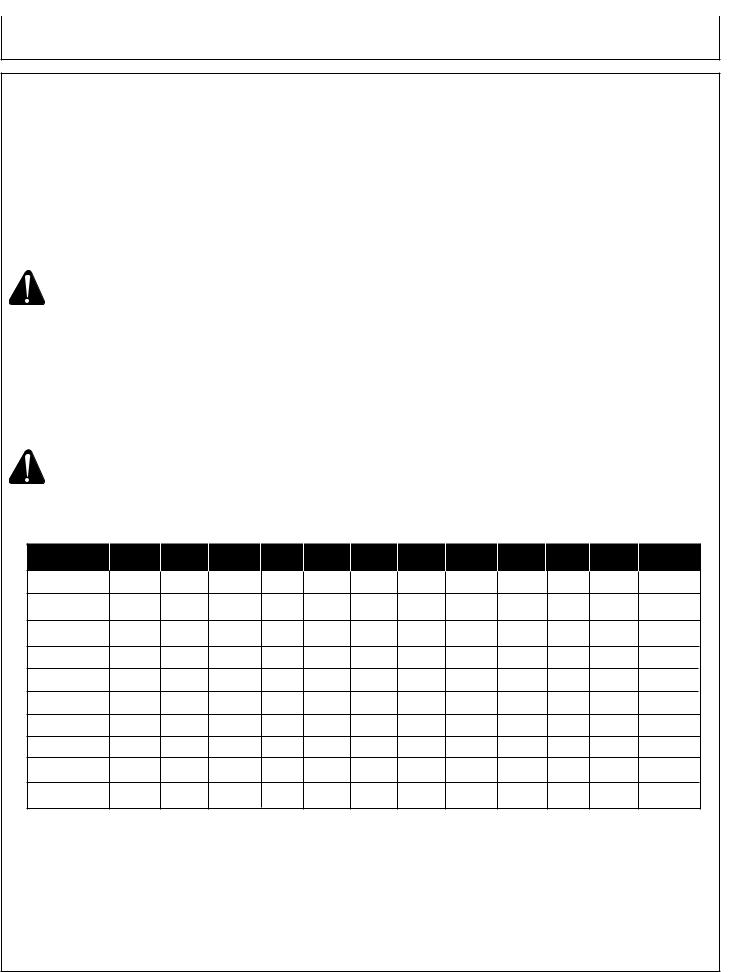
CABLE SIZE:
Equipment damage can result from low voltage. Therefore, to prevent excessive voltage drop between the generator and the equipment, the cable should be of adequate gauge for the length used. The cable selection chart gives the maximum cable lengths for various gauges of wire which can adequately carry the loads shown.
CURRENT |
LOAD IN WATTS |
|
MAXIMUM CABLE LENGTH (FEET) |
|
|||
IN AMPS |
120 VOLTS |
240 VOLTS |
#8 WIRE |
#10 WIRE |
#12 WIRE |
#14 WIRE |
#16 WIRE |
|
|
|
|
|
|
|
|
2.5 |
300 |
600 |
|
1000 |
600 |
375 |
250 |
5 |
600 |
1200 |
|
500 |
300 |
200 |
125 |
|
|
|
|
|
|
|
|
7.5 |
900 |
1800 |
|
350 |
200 |
125 |
100 |
10 |
1200 |
2400 |
|
250 |
150 |
100 |
50 |
15 |
1800 |
3600 |
|
150 |
100 |
65 |
|
20 |
2400 |
4800 |
175 |
125 |
75 |
50 |
|
25 |
3000 |
6000 |
150 |
100 |
60 |
|
|
30 |
3600 |
7200 |
125 |
65 |
|
|
|
40 |
4800 |
9600 |
90 |
|
|
|
|
|
|
|
|
|
|
|
|
ELECTRIC MOTOR LOADS:
It is characteristic of common electric motors in normal operation to draw up to six times their running current while starting. This table may be used to estimate the watts required to start “CODE G” electric motors.
CAUTION: If an electric motor fails to start or reach running speed, turn off the appliance or tool immediately to avoid equipment damage. Always check the requirements of the tool or appliance being used compared to the rated output of the generator.
|
|
WATTS REQUIRED TO START MOTOR |
||
MOTOR (H.P.) |
RUNNING WATTS |
REPULSION INDUCTION |
CAPACITOR |
SPLIT PHASE |
|
|
|
|
|
1/8 |
275 |
600 |
850 |
1200 |
1/6 |
275 |
600 |
850 |
2050 |
|
|
|
|
|
1/4 |
400 |
850 |
1050 |
2400 |
1/3 |
450 |
975 |
1350 |
2700 |
1/2 |
600 |
1300 |
1800 |
3600 |
|
|
|
|
|
3/4 |
850 |
1900 |
2600 |
|
1 |
1100 |
2500 |
3300 |
|
|
|
|
|
|
20 |
Operator’s Manual |
Troubleshooting
Symptom |
Problem |
Engine will not start. |
Engine switch is off. |
|
Fuel Tank empty. |
|
Fuel Valve is off. |
|
Inadequate engine oil. |
No spark at spark plug.
Generator has no output. |
Circuit breakers tripped. |
|
Inadequate cord sets or |
|
extension cords. |
Solution
Turn engine switch to the ON position.
Fill tank per instructions in this manual.
Turn Fuel Valve on.
Check oil level. This engine is equipped with a low oil sensor. The engine cannot be started unless the oil level is above the prescribed lower limit.
Remove the spark plug cap. Clean any dirt from around the plug base, then remove the spark plug. Install the spark plug in the plug cap. Turn the engine switch on.
Grounding the electrode to any engine ground, pull the recoil starter to see if sparks jump across the gap. If there is no spark, replace the plug.
Reinstall the plug and start engine according to instructions in this manual.
Consult John Deere Customer
Service.
Reset circuit breakers.
Check cord sets or extension cords capabilities in section Controls; Cable Size in this manual.
Consult John Deere Customer Service.
Operator’s Manual |
21 |
Service
MAINTENANCE
Keep all air vents clear.
Keep the generator clean. DO NOT spray with water.
Periodically check all fasteners and tighten, see the periodic maintenance chart.
GFCI TEST RECORDS:
As with any other safety devices, the GFCIs supplied with these generators must be checked every month to insure that they are functioning properly. To test the GFCIs, follow the instructions and then enter the date of the test below.
1.With the generator running and the idle control switch in the “START” position, push the “TEST” button. The “RESET” button should pop out. This should result in the power being off at both outlets of the duplex receptacle. Verify this by plugging a test lamp into each outlet.
WARNING: IF THE RESET BUTTON DOES NOT POP OUT, DO NOT USE THE RECEPTACLE(S). SEE AUTHORIZED John Deere Customer Service Representative FOR SERVICE IMMEDIATELY.
2.If the GFCI test correctly, restore power by FIRMLY pushing the “RESET” button back in until you hear or feel a distinctive “click”. IF THE GFCI FAILS TO RESET PROPERLY, DO NOT USE EITHER OUTLET OF THE DUPLEX RECEPTACLE. Have the unit serviced by an authorized John Deere Customer Service Representative immediately.
3.High vibration or severe mechanical shock loads may cause the GFCIs to trip. IF EITHER GFCI TRIPS BY ITSELF AT ANY TIME, reset it and perform test procedures 1 and 2.
4.Repeat steps 1-3 for the second GFCI.
WARNING: ALTHOUGH THE ABOVE TEST PROCEDURES WILL INDICATE PROPER GFCI OPERATION ON AN UNGROUNDED OR IMPROPERLY GROUNDED GENERATOR, THE GENERATOR MUST STILL
BE GROUNDED PER THE GROUNDING INSTRUCTIONS LISTED ON PAGE 16 FOR THE GFCI TO FUNCTION PROPERLY AND PROTECT THE USER FROM ELECTRICAL FAULTS.
Year |
Jan. |
Feb. March April May |
June July |
Aug. Sept. Oct. |
Nov. Dec. |
NOTE: Situations exist where a GFCI will not afford any protection against the hazards of electrical shock. Example: if a person touches two or more conductors from a damaged cord set and is not in direct contact with the ground, he or she may receive a shock. Since there is no path to ground for a ground fault current to flow through, the GFCI will not operate and serious injury may result.
The GFCI are merely an added safety feature. There are no substitutes for good safety precautions, correct electrical practices and proper maintenance of cords, equipment and connections.
22 |
Operator’s Manual |
Service
MAINTENANCE
EVAPORATIVE EMISSION COMPONENTS:
The unit you have purchased includes the following components that are in compliance with 2008 California Air Resources Board Evaporative Emission Standards;
1.Fuel Hose
2.Fuel Hose Fittings
These components should be inspected on a daily basis for cracks, leaks, and abnormal wear. If cracking, leaks or abnormal wear has occurred, the components should be replaced immediately.
ENGINE:
The engine for this generator is governed to operate at speeds close to 3600 RPM (60Hz) throughout the operating load range. The no load speed (before a load is applied) will be just a bit higher than the load speed and is normally set to 3750 RPM.
WARNING: DO NOT TAMPER WITH THE GOVERNOR MECHANISM, CHANGE THE SETTING EXPERIMENTALLY, OR PUSH THE THROTTLE OPEN IN AN ATTEMPT TO GENERATE MORE ELECTRICALCURRENT; EQUIPMENT DAMAGE OR PERSONAL INJURY MAY RESULT.
GOVERNOR SPEED ADJUSTMENT SHOULD BE MADE ONLY BY A JOHN DEERE Customer Service Representative.
CHECKING ENGINE OIL:
Check oil level before each operation and ensure that it is maintained per Preparing the Generator; Engine Oil Capacity section.
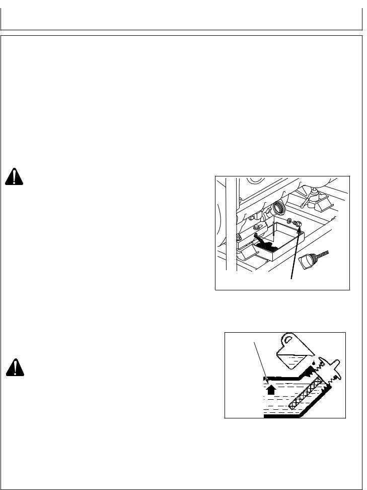
CHANGING ENGINE OIL:
Change oil after the first 20 hours of operation. Thereafter it should be changed every 100 hours.
1.Make sure the unit is on level ground. Run the engine to warm the oil.
2.Stop the engine.
3.Remove the oil drain plug. (See Fig. 6)
CAUTION: Oil being drained may be hot. To reduce the risk of burn injury, handle with care. Dispose of used oil properly.
4.Drain oil while engine is warm, into a suitable container.
5.Reinstall the oil drain plug.
6.Remove oil gauge and refill with new oil. (Fig. 7)
7.Check the oil level as instructed in Preparing the Generator; Engine Oil Capacity section.
8.Wipe up any spilled oil.
OIL DRAIN PLUG |
(Fig. 6)
UPPER LEVEL
(Fig. 7)
Operator’s Manual |
23 |
Service
MAINTENANCE
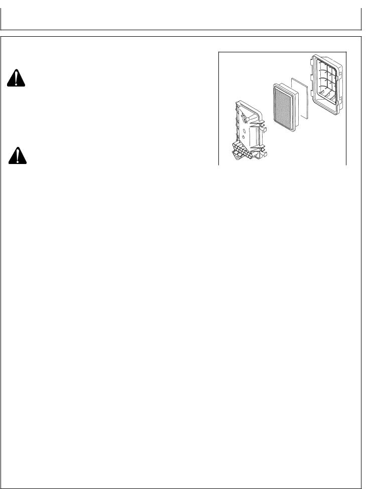
AIR CLEANER:
WARNING: RISK OF FIRE OR EXPLOSION. DO |
|
NOT USE GASOLINE OR LOW FLASH- |
|
POINT SOLVENTS TO CLEAN THE |
|
ELEMENT. CLEAN THE ELEMENT IN A |
|
WELL VENTILATED AREA. ENSURE |
|
THAT NO SPARKS OR FLAMES ARE |
|
NEAR THE WORKING AREA, THIS |
|
INCLUDES ANY APPLIANCE WITH A |
|
PILOT LIGHT. |
|
CAUTION: NEVER RUN THE ENGINE WITHOUT |
|
THE AIR FILTER, SERIOUS DANGER |
|
CAN RESULT. |
(Fig. 8) |
Check the air cleaner daily or before starting the engine. |
|
Check for and correct heavy buildup of dirt and debris along |
|
with loose or damaged components. (See Fig. 8) |
|
1. Unsnap the air cleaner cover and remove the elements. |
|
2. Clean the elements: |
|
FOAM PRE-CLEANER ELEMENT: Wash the foam pre- |
|
cleaner element in warm water with detergent. Rinse the |
|
foam pre-cleaner element thoroughly until all traces of |
|
detergent are eliminated. Squeeze out excess water, but do |
|
not wring. Allow the foam pre-cleaner element to air dry. |
|
Saturate the foam pre-cleaner element with new engine oil. |
|
Squeeze out all excess oil. DO NOT put engine oil on the |
|
foam damper. |
|
NOTE: Clean the foam pre-cleaner element every 25 hours |
|
of operation (more often under extremely dusty or |
|
dirty condition) |
|
PAPER AIR CLEANER ELEMENT: Do not wash the paper |
|
element or use pressurized air, as this will damage the |
|
element. Clean by gently tapping the element to remove |
|
dust. Replace the element if damaged, bent or extremely |
|
dirty. Handle new element carefully; do not use if the sealing |
|
surfaces are bent or damaged. |
|
NOTE: Replace the paper element every 100 hours (more |
|
often under extremely dusty conditions.) |
|
5. Reinstall the foam pre-cleaner element and the paper |
|
air cleaner element. Close air cleaner cover and clasp |
|
shut. |
|
24 |
Operator’s Manual |
Service
MAINTENANCE
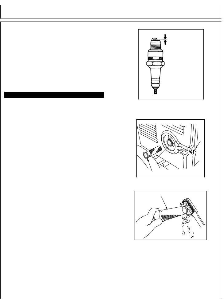
CLEANING AND GAPPING SPARK PLUG:
If the plug is contaminated with carbon, remove it using a plug cleaner or wire brush.
Check the spark plug gap and reset it if necessary. The spark plug gaps are listed below. To change the gap, bend the sideelectrode only, using a spark plug tool. (Fig. 9)
Install and tighten the spark plug. Connect the spark plug lead.
Recommended Spark Plug:
Engine |
Subaru |
Honda |
Spark Plug |
NGK BR-6HS |
NGK BPR6ES |
Spark Plug Gap |
0.6 - 0.7 mm |
0.7 - 0.8 mm |
|
(0.02-0.03 in.) |
(0.03 in.) |
Torque - New |
8.7-10.9 ft-lb |
|
Torque - Retighten |
16.6-19.5 ft-lb |
|
Spark Arrestor:
If the generator has been running, the muffler will be very hot. Allow it to cool before proceeding.
NOTE: Remove and clean spark arrester every 100 hours or as necessary.
NOTE: Product users on United States forest service land, and in some states, must comply with fire
prevention regulations.
Spark Plug Gap (See recommendations)
(Fig. 9)
SCREW |
SPARK ASSESTER |
(Fig. 10)
Clean the spark arrester as follows: (Fig. 10 and 11)
1.Loosen the screw by the exhaust port of the muffler and remove the spark arrester.
2.Use a brush to remove carbon deposits from the spark arrester screen. Inspect the screen for breaks or tears and replace it if necessary.
3.Install the spark arrester in the reverse order of removal.
Spark arrestors are available from your local John Deere Customer Service. Other user requirements may apply, check with your Federal, State or local authorities.
SPARK ARRESTER SCREEN
(Fig. 11)
Operator’s Manual |
25 |

Service
MAINTENANCE
PERIODIC MAINTENANCE CHART:
To ensure satisfactory operation over an extended period of time, an engine requires normal maintenance at regular intervals. The Periodic Maintenance Chart below shows periodic inspection and maintenance items and suitable intervals. The bullet mark designates that the corresponding item should be performed at that interval.
NOTE: Some adjustments require the use of special tools or other equipment. An electronic tachometer will facilitate setting idle and running speeds.
|
Daily |
Every |
Every |
Every |
Before |
|
|
|
25hrs. |
100 hrs. |
200 hrs. |
Storage |
|
|
|
|
|
|
|
|
Check fuel |
• |
|
|
|
|
|
Check engine oil |
• |
|
|
|
|
|
Check for loose or lost nuts and bolts |
• |
|
|
|
|
|
Check for leaks |
• |
|
|
|
|
|
Check cylinder and head fins for |
|
|
|
|
|
|
dust and dirt |
• |
|
|
|
|
|
Check battery electrolyte level |
• |
|
|
|
|
|
Check fuel lines (replace if necessary) |
• |
|
|
|
|
|
Clean air cleaner foam element (**) |
|
• |
|
|
|
|
Tighten nuts and bolts (*) |
|
|
• |
|
|
|
|
|
|
|
|
|
|
Change engine oil (*) |
|
|
• |
|
|
|
Clean fuel filter |
|
|
• |
|
|
|
Replace air cleaner paper element (**) |
|
|
• |
|
|
|
Clean dust and dirt from |
|
|
|
|
|
|
cylinder and cylinder head fins (**) |
|
|
• |
|
|
|
|
|
|
|
|
|
|
Clean and regap spark plug |
|
|
|
• |
|
|
Add fuel stabilizer |
|
|
|
|
• |
|
|
|
|
|
|
|
|
Run unit dry |
|
|
|
|
• |
|
|
|
|
|
|
|
|
* Perform these operations after the first 5 hours of use, then at the recommended intervals.
** Service more frequently under dusty conditions.
NOTE: These items must be performed with the proper tools. See your John Deere Customer Service Representative for service, unless you have the proper equipment and mechanical proficiency.
26 |
Operator’s Manual |

Storage
Service
Storing GENERATOR
SHORT TERM (1-6 months):
1.Add gasoline conditioner and stabilizer at the specified concentration.
2.Run the unit for two (2) minutes to ensure the mixed fuel is in the entire fuel system. Close the fuel valve and run the unit until it stops.
3.Remove the spark plug, pour 1-2 teaspoons (5-10cc) of engine oil into the cylinder, slowly pull the starter handle 2 or 3 times, reinstall the spark plug and tighten securely.
4.Clean the exterior surface of the generator and apply a rust inhibitor.
5.Store the generator in a dry, well ventilated place.
LONG TERM (More than 6 months):
1.Add gasoline conditioner and stabilizer at the specified concentration.
2.Run the generator until the fuel tank and carburetor are dry. As the engine is beginning to die, move the choke lever to the choke position.
NOTE: Turn off the idle control to decrease the run time.
3.Remove the spark plug, pour 1-2 teaspoons (5-10cc) of engine oil into the cylinder, slowly pull the starter handle 2 or 3 times, reinstall the spark plug and tighten securely.
4.Clean the exterior surface of the generator and apply a rust inhibitor.
5.Store the generator in a dry, well ventilated place.
WARNING: FUEL SHOULD BE DRAINED IN A
WELL VENTILATED AREA AND STORED
IN A CONTAINER APPROVED FOR
GASOLINE.
Operator’s Manual |
27 |
Specifications
Specifications
ITEM |
SPECIFICATION |
|
|
|
|
AC-g3010H |
AC-g4010S |
AC-g4010H |
AC-g5010S |
Engine |
Honda |
Subaru |
Honda |
Subaru |
Watts (AC) Rated |
3000 watts |
4000 watts |
4000 watts |
5000 watts |
Watts (AC) Max. |
2450 watts |
3500 watts |
3500 watts |
4400 watts |
Rated Voltage (AC) |
120V |
120/240V |
120/240V |
120/240V |
Max. Amperage |
25.0 |
33.3/16.7 |
33.3/16.7 |
41.7/20.8 |
Cont. Amperage |
20.4 |
29.2/14.6 |
29.2/14.6 |
36.7/18.3 |
Frequency |
60 |
60 |
60 |
60 |
Fuel Tank Capacity |
2.6 gal. |
5.68 gal. |
5.68 gal. |
5.68 gal. |
Run Time Hours / |
|
|
|
|
Tank of Fuel* |
7.4 hrs. |
9.3 hrs. |
9.3 hrs. |
6.8 hrs. |
* Rated at Full Load |
|
|
|
|
NOTE: Unit ratings are established based on operation at standard conditions of 60° F and at sea level. The performance of the generator must be de-rated for temperature and altitude by 1% for every 10° F above 60° F and 3.5% for every 1000 feet above sea level. Due to the operational characteristics of the thermal type circuit breaker, the power available from the generator will decrease slightly with a corresponding increase in ambient temperature.
Due to continuing product improvements, specifications are subject to change without notice.
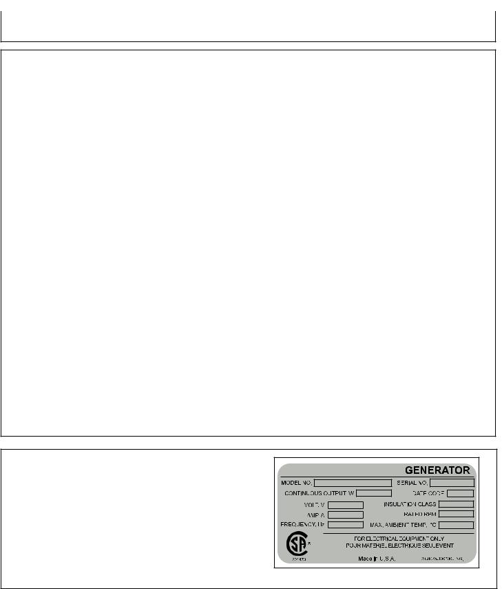
Record serial number
Write you model number, machine serial number and date of purchase in the spaces provided below. Your dealer needs this information when ordering parts.
Model No._______________________________________________
Machine Serial No.________________________________________
Date of Purchase_________________________________________
(To be filled in by purchaser)
28 |
Operator’s Manual |

Accessories
lifting hook KIT: AW-5090-0003 (AC-G4010S, AC-G4010H, AC-G5010S)
Used for lifting the generator safely. The Lifting Hook Kit includes the lifting hook, hardware and instructions needed to assemble the lifting hook to the generator.
wheel and handle kit: AW-5740-0007 (AC-G4010H, AC-G4010S,
AC-G5010S)
Allows easier portability of the generator. The Wheel and Handle Kit includes the wheels, handles, hardware and instructions needed to assemble the kit to the generator.
Operator’s Manual |
29 |

Warranty
STATEMENT OF WARRANTY
John Deere warrants all parts, (except those referred to below), of your new generator to be free from defects in materials and workmanship during the following periods:
For Two (2) Years from the date of original purchase.
Defective parts not subject to normal wear and tear will be repaired or replaced at our option during the warranty period. In any event, reimbursement is limited to the purchase price paid.
Exclusions
1.Engine/Motor and Generator are covered under separate warranty by its respective manufacturer and is subject to the terms set forth therein.
2.This warranty does not cover parts damaged due to normal wear, misapplication, misuse, operation at other than recommended . Failure to follow recommended operating and maintenance procedures also voids warranty.
3.The use of other than genuine manufacturer repair parts will void warranty.
4.Parts returned, prepaid to our factory or to an Authorized John Deere Service Center will be inspected and replaced free of charge if found to be defective and subject to warranty. There are no warranties which extend beyond the description of the face hereof. Under no circumstances shall the manufacturer bear any responsibility for loss of use of the unit, loss of time or rental, inconvenience, commercial loss or consequential damages.
For Service or Warranty Consideration, contact Mi-T-M® Corporation, 8650 Enterprise Drive, Peosta, IA 52068
563-556-7484 / 800-553-9053 / Fax 563-556-1235 Monday - Friday 8:00 a.m. - 5:00 p.m. CST
30 |
Operator’s Manual |
 Loading...