


AC-G3200i
AC-G4300i
Generator

Introduction
THANK YOU for purchasing a John Deere product.
READ THIS MANUAL carefully to learn how to operate and service your machine correctly. Failure to do so could result in personal injury or equipment damage.This manual and safety signs on your machine may also be available in other languages. (See your John Deere dealer to order.)
THIS MANUALSHOULD BE CONSIDERED a permanent part of your machine and should remain with the machine when you sell it.
MEASUREMENTS in this manual are given in both metric and customary U.S. unit equivalents. Use only correct replacement parts and fasteners. Metric and inch fasteners may require a specific metric or inch wrench.
RIGHT HAND AND LEFT HAND sides are determined by facing the control panel end of the machine.
The SERIAL NUMBER is located in the Specification or Identification Numbers section. Accurately record all the numbers to help in tracing the machine should it be stolen. Your dealer also needs these numbers when you order parts. File the identification numbers in a secure place off the machine.
WARRANTY is provided from your John Deere dealer for customers who operate and maintain their equipment as described in this manual. The warranty is explained on the warranty certificate shown in this manual.
This warranty provides you the assurance that your dealer will back products where defects appear within the warranty period. Should the equipment be abused, or modified to change its performance beyond the original factory specifications, the warranty will become void.
2 |
Operator’s Manual |

Introduction
NOTICE
FEDERAL EMISSION COMPONENT DEFECT WARRANTY and CALIFORNIA EMISSION CONTROL WARRANTY are applicable to only those engines / generators complied with EPA (Environmental Protection Agency) and CARB (California Air Resources Board) emission regulations in the U.S.A.
NOTICE
To the engines / generators exported to and used in the countries other than the U.S.A., warranty service shall be performed by the distributor in each country in accordance with the standard Robin engine / generator warranty policy as applicable.
AIR INDEX
To show compliance with California emission regulations, a hang tag has been provided displaying the Air Index level and durability period of this engine.
The Air Index level defines how clean an engine’s exhaust is over a period of time. A bar graph scaled from “0” (most clean) to “10” (least clean) is used to show an engine’s Air Index level. A lower Air Index level represents cleaner exhaust from an engine.
The period of time (in hours) that the Air Index level is measured is known as the durability period. Depending on the size of the engine, a selection of time periods can be used to measure the Air Index level (see below).
Descriptive Term |
Applicable to Emissions Durability Period |
Moderate: |
50 hours (engine from 0 to 80 cc) |
|
125 hours (engine greater than 80 cc) |
Intermediate: |
125 hours (engine from 0 to 80 cc) |
|
250 hours (engine greater than 80 cc) |
Extended: |
300 hours (engine from 0 to 80 cc) |
|
500 hours (engine greater than 80 cc) |
Notice: This hang tag must remain on the engine or piece of equipment, and only be removed by the ultimate purchaser before operation.
Operator’s Manual |
3 |

Introduction
FEDERAL EMISSIONS COMPONENT DEFECT WARRANTY
EMISSIONS COMPONENT DEFECT WARRANTY COVERAGE -- This emission warranty is applicable in all States, except the state of California.
Fuji Heavy Industries Ltd. and Robin America Inc., Wood Dale Illinois, (herein “ROBIN AMERICA”) warrant(s) to the initial retail purchaser and each subsequent owner, that this Non-road engine (herein “engine”) has been designed, built, and equipped to conform at the time of initial sale to all applicable regulations of the U.S.
Environmental Protection Agency (EPA), and that the engine is free of defects in materials and workmanship which would cause this engine to fail to conform with EPA regulations during its warranty period.
For the components listed under PARTS COVERED, the service dealer authorized by ROBIN AMERICA will, at no cost to you, make the necessary diagnosis, repair, or replacement necessary to ensure that the engine complies with applicable U.S. EPA regulations.
EMISSIONS COMPONENT DEFECT WARRANTY PERIOD
The warranty period for this engine begins on the date of sale to the initial purchaser and continues for a period of two years.
PARTS COVERED
Listed below are the parts covered by the Emission Components
Defect Warranty. Some of the parts listed below may require scheduled maintenance and are warranted up to the first scheduled replacement point for that part.
1.Fuel Metering System
a.Carburetor and internal parts (and / or pressure regulator or fuel injection system).
b.Air / fuel ratio feedback and control system, if applicable.
c.Cold start enrichment system, if applicable.
d.Regulator assembly (gasoline fuel, if applicable).
2.Air Induction System
a.Intake manifold, if applicable.
b.Air filter.
3.Ignition System
a.Spark plugs.
b.Magneto or electronic ignition system.
c.Spark advance / retard system, if applicable.
4.Exhaust manifold, if applicable.
5.Miscellaneous items used in above systems.
a.Electronic controls, if applicable.
b.Hoses, belts, connectors, and assemblies.
c.Filter lock assembly (gaseous fuel, if applicable).
OBTAINING WARRANTY SERVICE
To obtain warranty service, take your engine to the nearest authorized ROBINAMERICA. Bring your sales receipts indicating date of purchase for this engine. The service dealer authorized by ROBIN AMERICA will perform the necessary repairs or adjustments within a reasonable amount of time and furnish you with a copy of the repair order.All parts and accessories replaced under this warranty become the property of ROBIN AMERICA.
WHAT IS NOT COVERED
Conditions resulting from tampering, misuse, improper adjustment (unless they were made by the service dealer authorized by ROBIN AMERICA during a warranty repair), alteration, accident, failure to use the recommended fuel and oil, or not performing required maintenance services.
The replacement parts used for required maintenance services.
Consequential damages such as loss of time, inconvenience, loss of use of the engine or equipment, etc.
Diagnosis and inspection charges that do not result in warranty-eligible service being performed.
Any non-authorized replacement part, or malfunction of authorized parts due to use of non-authorized parts.
OWNER’S WARRANTY RESPONSIBILITIES
As the engine owner, you are responsible for the performance of the required maintenance listed in your owner’s manual. ROBINAMERICA recommends that you retain all receipts covering maintenance on your engine, but ROBIN AMERICA cannot deny warranty solely for the lack of receipts or for your failure to ensure the performance of all scheduled maintenance.
As the engine owner, you should however be aware that ROBIN AMERICA may deny warranty coverage if your engine or a part has failed due to abuse, neglect, improper maintenance or unapproved modifications.
You are responsible for the presenting your engine to the nearest service dealer authorized by ROBIN AMERICA when a problem exists.
If you have any questions regarding your warranty rights and responsibilities, you should contact the ROBIN AMERICA customer service department at 1-630-350-8200 for the information.
THINGS YOU SHOULD KNOW ABOUT THE EMISSION CONTROL SYSTEM WARRANTY MAINTENANCE AND REPAIRS
You are responsible for the proper maintenance of the engine. You should keep all receipts and maintenance records covering the performance of regular maintenance in the event questions arise. These receipts and maintenance records should be transferred to each subsequent owner of the engine. ROBINAMERICAreserves the right to deny warranty coverage if the engine has not been properly maintained. Warranty claims will not be denied, however, solely because of the lack of required maintenance or failure to keep maintenance records.
MAINTENANCE, REPLACEMENT OR REPAIR OF EMISSION CONTROLDEVICESAND SYSTEMS MAY BE PERFORMED BYANY REPAIR ESTABLISHMENT OR INDIVIDUAL;
HOWEVER, WARRANTY REPAIRS MUST BE PERFORMED BY A SERVICE DEALER AUTHORIZED BY ROBIN AMERICA. THE USE OF PARTS THAT ARE NOT EQUIVALENT IN PERFORMANCE
AND DURABILITY TO AUTHORIZED PARTS MAY IMPAIR THE EFFECTIVENESS OFTHE EMISSION CONTROLSYSTEMAND MAY HAVE A BEARING ON THE OUTCOME OF A WARRANTY CLAIM.
If other than the parts authorized by ROBIN AMERICA are used for maintenance replacements or for the repair of components affecting emission control, you should assure yourself that such parts are warranted by their manufacturer to be equivalent to the parts authorized by ROBIN AMERICA in their performance and durability.
HOW TO MAKE A CLAIM
All repair qualifying under this limited warranty must be performed by a service dealer authorized by ROBIN AMERICA. In the event that any emission-related part is found to be defective during the warranty period, you shall notify ROBINAMERICAcustomer service department at 1-630-350-8200 and you will be advised of the appropriate warranty service dealer or service providers where the warranty repair can be performed.
4 |
Operator’s Manual |

Introduction
CALIFORNIA EMISSION CONTROL WARRANTY STATEMENT
YOUR WARRANTY RIGHTS AND OBLIGATIONS
The California Air Resources Board and Fuji Heavy Industries Ltd. (herein “FUJI”) are pleased to explain the emission control system warranty on your 2004 and later Small Off-Road engine (herein “engine”). In California, new engine must be designed, built and equipped to meet the State’s stringent anti-smog standards. FUJI must warrant the emission control system on your engine for the periods of time described below, provided there has been no abuse, neglect or improper maintenance of your engine. Your emission control system may include parts such as the carburetor or fuel-injection system, and the ignition system. Also included may be hoses, belts, connectors and other emission-related assemblies. Where a warrantable condition exists, ROBIN AMERICA will repair your engine at no cost to you including diagnosis, parts and labor.
MANUFACTURER’S WARRANTY COVERAGE:
The 2004 and later engines are warranted for two (2) years. If any emission related part on your engine is defective, the part will be repaired or replaced by ROBIN AMERICA.
OWNER’S WARRANTY RESPONSIBILITIES:
-As the engine owner, you are responsible for the performance of the required maintenance listed in your Owner’s Manual. ROBIN AMERICA recommends that you retain all receipts covering maintenance on your engine, but FUJI cannot deny warranty solely for the lack of receipts or for your failure to ensure the performance of all scheduled maintenance.
-As the engine owner, you should however, be aware that FUJI may deny you warranty coverage if your engine or a part has failed due to abuse, neglect, improper maintenance or unapproved modifications.
-Your are responsible for presenting your engine to a service dealer or warranty station authorized by ROBIN AMERICA Inc. 940 Lively Blvd., Wood Dale, IL 60191 (herein ROBIN AMERICA) as soon as a problem exists. The warranty repairs should be completed in a reasonable amount of time, not to exceed 30 days.
If you have any questions regarding your warranty rights and responsibilities, you should contact Robin America Inc. Customer Service Department at 1-630-350-8200.
LIMITED WARRANTY
on Emission Control Systems - California Only -
FUJI warrants to the owner of the 2004 and later engine that the engine (1) has been designed, built and equipped so as to conform at the time of manufacture with the applicable regulations of the California Air Resources Board, and (2) is free from defects in materials and workmanship that could cause it to fail to conform with those regulations as may be applicable in the terms and conditions stated below.
A. COMMENCEMENT DATE
The warranty period begins on the date the engine is delivered to a first retail purchaser.
B. LENGTH OF COVERAGE
FUJI warrants to a first retail purchaser and each subsequent purchaser that the engine is free from defects in materials and workmanship that cause the failure of a warranted emission-related part for a period of two (2) years after the date of delivery to the first retail purchaser.
C. WHAT IS COVERED
1. REPAIR OR REPLACEMENT PARTS
Repairs and replacement of any warranted part will be performed at no charge to you by an authorized service dealer or a warranty station. You may contact the Robin America Inc. Customer Service
Department at 1-630-350-8200 to obtain the name of the nearest appropriate location where your warranty repairs are performed.
2. WARRANTY PERIOD
This warranty continues for a period of two (2) years and applies only to the repair, replacement or adjustment of the component parts that are not scheduled for replacement as required maintenance. Further, component parts which are scheduled only for regular inspection to the effect of “repair or replace as necessary” are warranty for the warranty period. Any warranted part which is scheduled for replacement as required maintenance is warranted for the period of time up to the first scheduled replacement point for that part.
3. DIAGNOSIS
You will not be charged for diagnostic labor that leads to the determination that a warranted part is defective, if the diagnostic work is performed at an authorized service dealer or warranty station.
4. DAMAGES
If a warranted part failed causing damage to the engine components, consult an warranty station.
D. WHAT IS NOT COVERED
1.This limited warranty does not cover any part which malfunctions, fails or is damaged due to failure to follow the maintenance and operating instructions set forth in the 2004 and later Owner’s Manual including:
a.Improper maintenance of any warranted parts.
b.Improper installation, adjustment or repair of the engine or of any warranted part unless performed by an authorized service dealer.
c.Failure to follow recommendations on fuel use contained in the 2004 and later Owner’s Manual.
d.Repairs performed outside of the authorized warranty service dealers.
e.Use of parts which are not authorized by FUJI.
2.Add-on or modified parts.
This warranty does not cover any part that malfunctions, fails or is damaged due to alterations by changing, adding to or removing parts from the engine.
3.Expenses incurred by processing warranty-claims. FUJI, any authorized service dealer and warranty station
shall not be liable for any loss of use of the engine, for any alternative usage, for any damage to goods, loss of time or inconvenience.
E. HOW TO FILE A CLAIM
All repairs qualifying under this Limited Warranty must be performed by a dealer who sold you the engine or warranty station authorized by ROBIN AMERICA. In the event that any emission-related part is found to be defective during the warranty period, you must notify the Robin America Inc. Customer Service Department at 1-630-350-8200 and you will be advised of the appropriate warranty service facilities where the warranty repair is to be performed.
Operator’s Manual |
5 |

Introduction
F. WHERE TO OBTAIN WARRANTY SERVICE
It is recommended that warranty service be performed by the authorized dealer who sold you the engine, although warranty service will be performed by any authorized service dealers or warranty stations anywhere in the United States.
When warranty repair is needed, the engine must be brought to an authorized service dealer or warranty station’s place of business during normal business hours. In all cases, a reasonable time, not to exceed 30 days, must be allowed for the warranty repair to be completed after the engine is received by the authorized service dealer or warranty station.
G.MAINTENANCE, REPLACEMENT AND REPAIR OF EMISSION-RELATED PARTS
Only warranted engine replacement parts approved by FUJI should be used in the performance of any warranty maintenance or repairs on emission-related parts. If other than authorized parts are used for maintenance, replacement or repair of components affecting emission control, you should assure yourself that such parts are warranted by their manufacturer to be equivalent to authorized parts in performance and durability. FUJI, however, assumes no liability under this warranty with respect to parts other than authorized parts. The use of nonauthorized replacement parts does not invalidate the warranty on other components unless the non-authorized parts cause damage to warranted parts.
I. MAINTENANCE STATEMENTS
H. PARTS COVERED UNDER THE CALIFORNIAEMISSIONS WARRANTY
1. Fuel Metering System
a.Carburetor and internal parts (and / or pressure regulator or fuel, injection system).
b.Air / fuel ratio feedback and control system, if applicable.
c.Cold start enrichment system, if applicable.
d.Regulator assembly (gaseous fuel, if applicable).
2.Air Induction System
a.Intake manifold, if applicable.
b.Air filter.
3.Ignition System
a.Spark Plug.
b.Magneto or electronic ignition system.
c.Spark advance / retard system, if applicable.
4.Exhaust manifold, if applicable.
5.Miscellaneous items used in above systems.
a.Electronic controls, if applicable.
b.Hoses, belts, connectors, and assemblies.
c.Filter lock assembly (gaseous fuel, if applicable).
It is your responsibility to have all scheduled inspection and maintenance services performed at the times recommended in the 2005 and later Owner’s Manual and to retain proof that inspection and maintenance services are performed at the times when recommended. FUJI will not deny a warranty claim solely because you have no record of maintenance; however, FUJI may deny a warranty claim if your failure to perform required maintenance resulted in the failure of warranted part. The proof which you maintain should be given to each subsequent owner of the engine. You are responsible for performing the scheduled maintenance described below based on the procedures specified in the 2005 and later Owner’s Manual. The scheduled maintenance below is based on a normal engine operating schedule.
PROCEDURE:
1.Change engine oil.
2.Clean air cleaner (element).
3.Replace air cleaner element.
4.Clean and adjust spark plug and electrodes.
INTERVAL:
1.Initial 20 hours and every 100 hours afterward.
2.Every 50 hours.
3.Every 200 hours.
4.Every 200 hours.
NOTE: More frequent maintenance may be necessary under dusty, dirty or severe conditions.
6 |
Operator’s Manual |

|
Contents |
|
Page |
Safety ........................................................................ |
8 |
Safety Signs ........................................................... |
15 |
Controls ................................................................. |
17 |
Preparing the Generator ........................................ |
20 |
Operation ................................................................ |
26 |
Troubleshooting ..................................................... |
33 |
Service .................................................................... |
34 |
Transporting............................................................. |
38 |
Storage .................................................................... |
39 |
Specifications ......................................................... |
40 |
Wire Diagram ........................................................... |
41 |
Warranty ............................................................. |
42-44 |
Notes ........................................................................ |
45 |
All information, illustrations and specifications in this manual are based on the latest information available at the time of publication. The right is reserved to make changes at any time without notice.
Operator’s Manual |
7 |
Safety
RECOGNIZE SAFETY INFORMATION
This is the safety alert symbol. When you see this symbol on your machine or in this manual, be alert to the potential for personal injury.
Follow recommended precautions and safe operating practices.
UNDERSTAND SIGNAL WORDS
Asignal word--DANGER, WARNING or CAUTION--is used with the safety-alert symbol. DANGER identifies the most serious hazards.
DANGER or WARNING safety signs are located near specific hazards. General precautions are listed on CAUTION safety signs. CAUTION also calls attention to safety messages in this manual.
FOLLOW SAFETY INSTRUCTIONS
Carefully read all safety messages in this manual and safety signs on your machine. Keep safety signs in good condition. Replace missing or damaged safety signs. Be sure new equipment components and repair parts include the current safety signs. Replacement safety signs are available from your John Deere dealer.
Learn how to operate the machine and how to use controls properly. Do not let anyone operate without instruction.
Keep your machine in proper working condition. Unauthorized modifications to the machine may impair the function and/or safety and affect machine life.
If you do not understand any part of this manual and need assistance, contact your John Deere dealer.
|
|
|
|
|
|
|
|
|
|
|
|
|
|
|
|
|
|
N |
|
|
|
||
|
|
|
|
|
|
|
|
|
|
|
|
|
|
|
|
IO |
|
|
SIN |
||||
|
|
|
|
|
|
|
|
|
|
|
|
|
|
|
T |
|
|
|
|
||||
|
|
|
|
|
|
|
|
|
|
|
|
|
|
U |
|
|
|
ON |
|
S |
|||
|
|
|
|
|
|
|
|
|
|
|
|
|
A |
|
|
|
TI |
|
|
|
|||
|
|
|
|
|
|
|
|
|
|
|
|
C |
|
|
|
AU |
|
|
|
AL |
|||
|
|
|
|
|
|
|
|
|
|
|
|
|
|
|
|
OC |
|
|
NU |
|
|||
|
|
|
|
|
|
G |
|
|
|
|
|
|
IN |
|
|
HEMA |
|
SIN |
|||||
|
|
|
|
|
|
|
|
|
|
|
NS |
|
OT |
|
ION |
LS |
|||||||
|
|
|
|
|
|
|
|
|
|
|
|
|
|
|
|
UT |
|
|
|
||||
|
|
|
|
|
N |
|
|
|
|
TIO |
ALS |
|
O |
CA |
|
|
|
UA |
|||||
|
|
|
NI |
|
|
|
AU |
|
|
|
|
|
AN |
|
|||||||||
|
R |
|
|
|
OC |
|
|
NU |
|
|
|
|
|
EM |
|
|
|
||||||
A |
|
|
|
IN |
|
|
|
|
EMA |
SIN |
|
OTH |
|
|
|
|
|
||||||
W |
|
|
GS |
|
O |
TH |
|
ION |
|
LS |
|
|
|
|
|
|
|
|
|
||||
|
|
|
|
. |
|
|
|
UT |
|
|
|
|
|
|
|
|
|
|
|||||
|
|
IN |
|
|
O |
CA |
|
UA |
|
|
|
|
|
|
|
|
|
||||||
RN |
|
|
LS |
|
|
|
AN |
|
|
|
|
|
|
|
|
|
|
|
|||||
WA |
|
|
NUA |
|
|
|
|
|
EM |
|
|
|
|
|
|
|
|
|
|
|
|||
HEMA |
SIN |
OTH |
|
|
|
|
|
|
|
|
|
|
|
|
|||||||||
T |
|
|
ING |
|
. |
|
|
|
|
|
|
|
|
|
|
|
|
|
|
|
|
|
|
|
RN |
|
LS |
|
|
|
|
|
|
|
|
|
|
|
|
|
|
|
|
|
|||
A |
|
|
UA |
|
|
|
|
|
|
|
|
|
|
|
|
|
|
|
|
|
|
||
W |
|
|
AN |
|
|
|
|
|
|
|
|
|
|
|
|
|
|
|
|
|
|
|
|
|
EM |
|
|
|
|
|
|
|
|
|
|
|
|
|
|
|
|
|
|
|
|
||
TH |
|
|
|
|
|
|
|
|
|
|
|
|
|
|
|
|
|
|
|
|
|
|
|
8 |
Operator’s Manual |

CARBON MONOXIDE - POISONOUS GAS
Use generator outdoors, away from open windows, vents, or doors. Keep generator at least 1 meter (3 feet) away from any structure or building during use.
Generator exhaust contains carbon monoxide - a poisonous gas that can kill you. You CAN NOT smell or see this gas.
Never use a generator in enclosed or partially-enclosed spaces. Generators can produce high levels of carbon monoxide very quickly. When you use a portable generator, remember that you cannot smell or see carbon monoxide. Even if you can’t smell exhaust fumes, you may still be exposed to carbon monoxide.
If you start to feel sick, dizzy, or weak while using a generator, get to fresh air RIGHT AWAY. DO NOT DELAY. The carbon monoxide from generators can rapidly lead to full incapacitation and death.
If you experience serious symptoms, get medical attention immediately. Inform medical staff that carbon monoxide poisoning is suspected. If you experienced symptoms while indoors, have someone call the fire department to determine when it is safe to re-enter the building.
NEVER operate the generator in an explosive atmosphere, near combustible materials or where ventilation is not sufficient to carry away exhaust fumes. Exhaust fumes can cause serious injury or death.
NEVER use a generator indoors, including in homes, garages, basements, crawl spaces, and other enclosed or partially-enclosed areas, even with ventilation. Opening doors and windows or using fans will not prevent carbon monoxide build-up in the home.
Follow the instructions that come with your generator. Locate the unit outdoors and away from doors, windows, and vents that could allow the carbon monoxide gas to come indoors.
ONLY run generator outdoors and away from air intakes.
NEVER run generator inside homes, garages, sheds, or other semi-enclosed spaces. These spaces can trap poisonous gases EVEN IF you run a fan or open doors and windows.
If you start to feel sick, dizzy, or weak while using the generator, shut if off and get fresh air RIGHT AWAY. See a doctor. You may have carbon monoxide poisoning.
Install battery-operated carbon monoxide alarms or plug-in carbon monoxide alarms with battery back-up in your home, according to the manufacturer’s installation instructions. The carbon monoxide alarms should be certified to the requirements of the latest safety standards for carbon monoxide alarms. (UL 2034, IAS 6-96, or CSA 6.19.01).
Test your carbon monoxide alarm frequently and replace dead batteries.
Operator’s Manual |
9 |
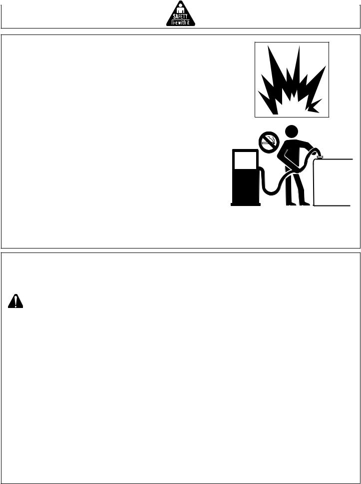
SAFETY WARNING WHEN REFUELING
Gasoline is extremely flammable and its vapors can explode if ignited.
Observe all safety regulations for the safe handling of fuel. Handle fuel in safety containers. If the container does not have a spout, use a funnel.
Do not overfill the fuel tank, leave room for the fuel to expand.
Do not refill fuel tank while the engine is running. Before refueling the generator, turn it off and let it cool down. Gasoline spilled on hot engine parts could ignite.
Fill the tank only on an area of bare ground. While fueling the tank, keep heat, sparks and open flame away. Carefully clean up any spilled fuel before starting engine.
Always fill fuel tank in an area with plenty of ventilation to avoid inhaling dangerous fumes.
NEVER store fuel for your generator in the home. Gasoline, propane, kerosene, and other flammable liquids should be stored outside of living areas in properly-labeled, non-glass safety containers. Do not store them near a fuel-burning appliance, such as a natural gas water heater in a garage. If the fuel is spilled or the container is not sealed properly, invisible vapors from the fuel can travel along the ground and can be ignited by the appliance’s pilot light or by arcs from electric switches in the appliance.
GROUND FAULT CIRCUIT INTERRUPTER PROTECTION
These generators are equipped with a GFCI (Ground Fault Circuit Interrupters) 120V duplex receptacles for protection against the hazards of electrical shock from defective attachments such as, tools, cords, and cables.
WARNING: The GFCI may not function unless the generator is properly grounded. Follow the correct procedure specified in the section labeled “GROUNDING INSTRUCTIONS”.
A GFCI is a device that interrupts electricity from either the utility or generator by means of a special type of circuit breaker if a fault current flow to the ground occurs.
A GFCI can be used only with generators that have the neutral wire internally bonded to the frame, and the frame properly grounded to the earth. A GFCI will not work on generators that do not have the neutral wire bonded to the frame, or on generators which have not been properly grounded. All John Deere generators have internally bonded ground wires. A GFCI will not work if the unit is not properly grounded.
A GFCI may be required by OSHA regulations, the National Electric Code and/or local and federal codes when operating a generator.
For additional protections against shock hazards due to defective equipment attached to the twist-lock receptacles, consider the use of a GFCI on each of these receptacles as well.
GFCI and GFCI protected cord sets and cables may be purchased from local electrical supply houses.
10 |
Operator’s Manual |
ELECTRICAL HAZARDS
This product must be grounded. If it should malfunction or breakdown, grounding provides a path of least resistance for electric current to reduce the risk of electric shock.
DANGER - IMPROPER CONNECTION OF THE EQUIPMENTGROUNDING CONDUCTOR CAN RESULT IN A RISK OF ELECTROCUTION. CHECK WITH A QUALIFIED ELECTRICIAN OR SERVICE PERSON IF YOU ARE IN DOUBT AS TO WHETHER THE UNIT IS PROPERLY GROUNDED.
This generator is equipped with a grounding terminal for your protection. Always complete the ground path from the generator to an external ground source as instructed in the section labeled “Grounding Instructions” in the Preparation section of this manual.
The generator is a potential source of electrical shock if not kept dry. Keep the generator dry and do not use in rain or wet conditions. To protect from moisture, operate it on a dry surface under an open, canopy-like structure. Dry your hands if wet before touching the generator.
Plug appliances directly into the generator. Or, use a heavy duty, outdoor-rated extension cord that is rated (in watts or amps) at least equal to the sum of the connected appliance loads. Check that the entire cord is free of cuts or tears and that the plug has all three prongs, especially a grounding pin.
NEVER try to power the house wiring by plugging the generator into a wall outlet, a practice known as “back feeding”. This is an extremely dangerous practice that presents an electrocution risk to utility workers and neighbors served by the same utility transformer. It also bypasses some of the built-in household circuit protection devices.
If you must connect the generator to the house wiring to power appliances, have a qualified electrician install the appropriate equipment in accordance with local electrical codes. Or, check with your utility company to see if it can install an appropriate power transfer switch.
For power outages, permanently installed stationary generators are better suited for providing backup power to the home. Even a properly connected portable generator can become overloaded. This may result in overheating or stressing the generator components, possibly leading to a generator failure.
Operator’s Manual |
11 |

IMPORTANT SAFETY INSTRUCTIONS
WARNING: To reduce the risk of injury, read this operator’s manual completely before using. When using this product, the following basic precautions should always be followed:
1.Read all the instructions before using the product.
2.Do not enclose the generator nor cover it with a box. The generator has a built-in forced air cooling
system, and may become overheated if it is enclosed. If generator has been covered to protect if from the weather during non use, be sure to remove it and keep it well away from the area during generator use.
3.Operate the generator on a level surface. It is not necessary to prepare a special foundation for the generator. However, the generator will vibrate on an irregular surface, so choose a level place without surface irregularities.
If the generator is tilted or moved during operation, fuel may spill and/or the generator may tip over, causing a hazardous situation.
Proper lubrication cannot be expected if the generator is operated on a steep incline or slope. In such a case, piston seizure may occur even if the oil is above the upper level.
4.Pay attention to the wiring or extension cords from the generator to the connected device. If the wire is under the generator or in contact with a vibrating part, it may break and possibly cause a fire, generator burnout, or electric shock hazard. Replace damaged or worn cords immediately.
5.Do not operate in rain, in wet or damp conditions, or with wet hands. The operator may suffer severe electric shock if the generator is wet due to rain or snow.
6.If wet, wipe and dry it well before starting. Do not pour water directly over the generator, nor wash it with water.
7.Be extremely careful that all necessary electrical grounding procedures are followed during each and every use. Failure to do so can be fatal.
8.NEVER try to power the house wiring by plugging the generator into a wall outlet, a practice known as “back feeding”. This is an extremely dangerous practice that presents an electrocution risk to utility workers and neighbors served by the same utility transformer. It also bypasses some of the built-in household circuit protection devices.
If you must connect the generator to the house wiring to power appliances, have a qualified electrician install the appropriate equipment in accordance with local electrical codes. Or, check with your utility company to see if it can install an appropriate power transfer switch.
9.No smoking while charging a battery. The battery emits flammable hydrogen gas, which can explode if exposed to electric arcing or open flame. Keep the area wellventilated and keep open flames / sparks away when charging a battery.
|
|
|
|
|
|
|
N |
|
|
|
|
|
|
IO |
SIN |
||
|
|
|
|
UT |
||||
|
|
|
CA |
O |
CAUTIONUALS |
|||
|
|
|
|
|
THE |
MAN |
|
|
|
|
G |
NSIN |
O |
NSIN |
|||
|
|
|
UTIO |
LS |
||||
RNIN |
OCAUTIONUALS |
OCAEMANUA |
||||||
WA |
GSIN |
HEMA NSIN |
OTH |
|
|
|||
|
OT UTIO |
LS |
|
|
|
|
||
RNIN |
LS. |
OCA ANUA |
|
|
|
|
||
WA |
ANUA |
HEM |
|
|
|
|
|
|
EM |
SIN |
OT |
|
|
|
|
|
|
TH |
ING . |
|
|
|
|
|
|
|
ARN |
ALS |
|
|
|
|
|
|
|
W |
MANU |
|
|
|
|
|
|
|
THE |
|
|
|
|
|
|
|
|
12 |
Operator’s Manual |

IMPORTANT SAFETY INSTRUCTIONS
10.Engine becomes extremely hot during and for some time after operation. Keep combustible materials well away from generator area. Be very careful not to touch any parts of the hot engine especially the muffler area or serious burns may result.
11.Keep children and all bystanders at a safe distance from work area.
12.It is absolutely essential that you know the safe and proper use of the power tool or appliance that you intend to use. All operators must read, understand and follow the tool / appliance owners manual. Tool and appliance applications and limitations must be understood. Follow all directions given on labels and warnings. Keep all instruction manuals and literature in a safe place for future reference.
13.Use only “LISTED” extension cords. When a tool or appliance is used outdoors, use only extension cords marked “For Outdoor Use”. Extension cords, when not in use should be stored in a dry and well ventilated area.
14.Always switch off generator’s AC circuit breaker and disconnect tools or appliances when not in use, before servicing, adjusting, or installing accessories and attachments.
15.Make sure the engine is stopped before starting any maintenance, servicing or repair.
NOTE: Make sure maintenance and repair of the generator set are performed by properly trained personnel only.
SAVE THESE INSTRUCTIONS
|
|
|
|
|
|
|
|
N |
|
|
|
|
|
|
|
IO |
NSIN |
||
|
|
|
|
|
UT |
||||
|
|
|
|
CA |
O |
CAUTIO UALS |
|||
|
|
G |
|
NSIN |
|
THE |
NSIN |
||
|
|
|
O |
|
UTIO |
LS |
|||
RNIN |
OCAUTIONUALS |
OCAEMANUA |
|||||||
WA |
GSIN |
HEMA NSIN |
OTH |
|
|
||||
|
OT |
TIO |
LS |
|
|
|
|
||
RNIN |
LS. |
OCAU ANUA |
|
|
|
|
|||
WA |
ANUA |
|
HEM |
|
|
|
|
|
|
EM |
SIN |
OT |
|
|
|
|
|
||
TH |
ING . |
|
|
|
|
|
|
|
|
ARN |
ALS |
|
|
|
|
|
|
|
|
W |
MANU |
|
|
|
|
|
|
|
|
THE |
|
|
|
|
|
|
|
|
|
Operator’s Manual |
13 |
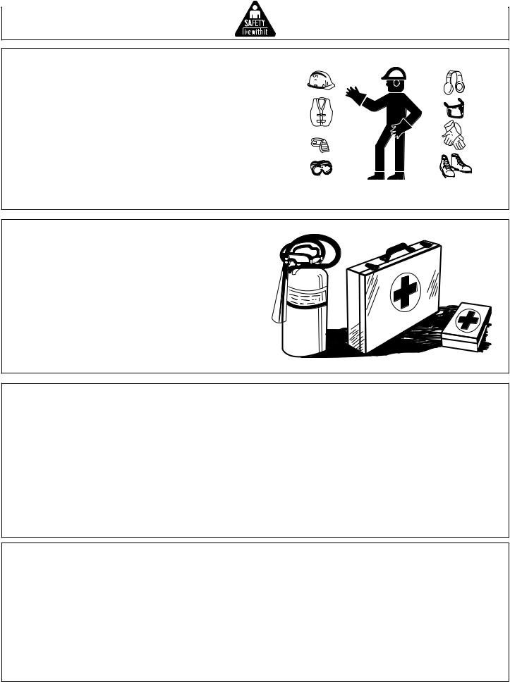
WEAR PROTECTIVE CLOTHING
Wear close fitting clothing and safety equipment appropriate to the job.
Wear a suitable hearing protective device such as earmuffs or earplugs to protect against objectionable or uncomfortable loud noises.
Operating equipment safely requires the full attention of the operator. Do not wear radio or music headphones while operating machine.
PREPARE FOR EMERGENCIES
Keep a first aid kit and fire extinguisher handy.
Keep emergency numbers for doctors, ambulance service, hospital and fire department near your telephone.
Be prepared if a fire starts.
INSPECT GENERATOR
Be sure all covers, guards and shields are tight and in place.
Locate all operating controls and safety labels.
Inspect power cord for damage before using. There is a hazard of electrical shock from crushing, cutting or heat damage.
SERVICE GENERATOR SAFELY
Before servicing the generator, disconnect all equipment and allow unit to cool down.
Service generator in a clean dry flat area.
Make sure the engine is stopped before starting any maintenance servicing or repair.
14 |
Operator’s Manual |
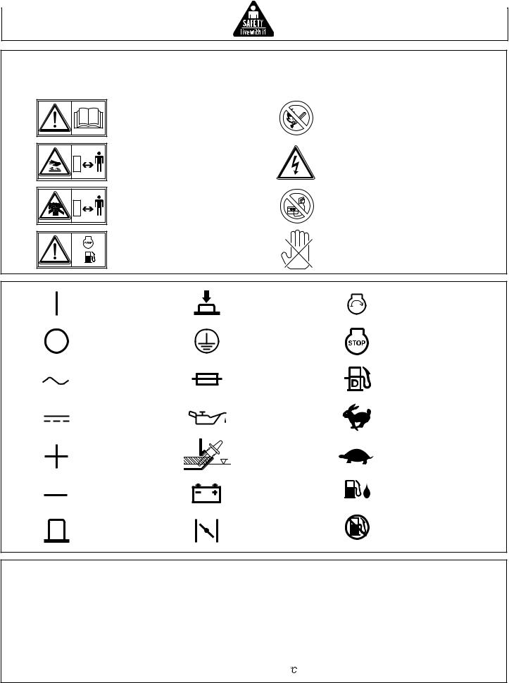
SAFETY SIGNS
In accordance with the European requirements (eec Directives), the specified symbols as shown in the following table are used for the products and this instructions manual.
Read the operator's instruction manual.
Stay clear of the hot surface.
Exhaust gas is poisonous.
Do not operate in an unventilated room.
Fire, open light and smoking prohibited.
Caution, risk of electric shock.
Do not connect the generator to the commercial power lines.
Stop the engine before refueling.
HOT, avoid touching the hot areas.
ON |
IN-position of a |
Engine start |
|
(power and Engine) |
bistable push control |
(Electric start) |
|
OFF |
Protective earth |
Engine stop |
|
(power and Engine) |
(ground) |
||
Alternating current |
Fuse |
Diesel fuel |
|
Direct current |
Engine oil |
Fast |
|
Plus ; |
Add oil |
Slow |
|
positive polarity |
|||
|
|
||
Minus ; |
Battery charging |
Run |
|
negative polarity |
condition |
|
|
OUT-position of a |
Choke ; |
Stop |
|
bistable push control |
cold starting aid |
|
P r Rated power (kW)
f r Rated frequency (Hz)
H max |
Maximum site altitude |
above sea-level (m) |
COP |
Continuous power |
U r |
Rated voltage (V) |
T max |
Maximum ambient |
temperature ( ) |
COS r Rated power factor
I r |
Rated current (A) |
mMass (kg)
Operator’s Manual |
15 |

SAFETY SIGNS |
|
|
Location: Control Panel |
|
Location: Gas Tank |
|
Location: Gas Tank |
16 |
Operator’s Manual |
|
Controls |
|
|
||
CONTROLS |
|
|
|
|
|
B |
C |
|
|
|
|
|
|
|
D |
|
|
A |
|
|
|
E |
|
|
|
|
|
|
|
|
|
|
F |
|
|
|
H |
I |
|
|
|
|
|
|
J |
K |
L |
P |
|
|
|
|
|
|
G |
O |
N |
|
M |
|
|
|
|
||
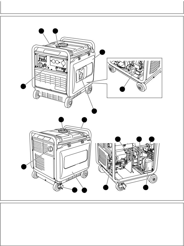
A-- |
Control Panel |
E-- |
Oil Drain Plug |
I-- |
Frame |
M-- |
Battery |
B-- |
Fuel Tank |
F-- |
Recoil Starter (Handle) |
J-- |
Spark Plug Cap |
N-- |
Oil Gauge |
C-- |
Fuel Gauge |
G-- |
Brake |
K-- |
Air Cleaner |
O-- |
Side Panel (L) |
D-- |
Side Panel (R) |
H-- |
Tank Cap |
L-- |
Fuel Strainer |
P-- |
Exhaust Outlet |
Operator’s Manual |
17 |
Controls
CONTROLS
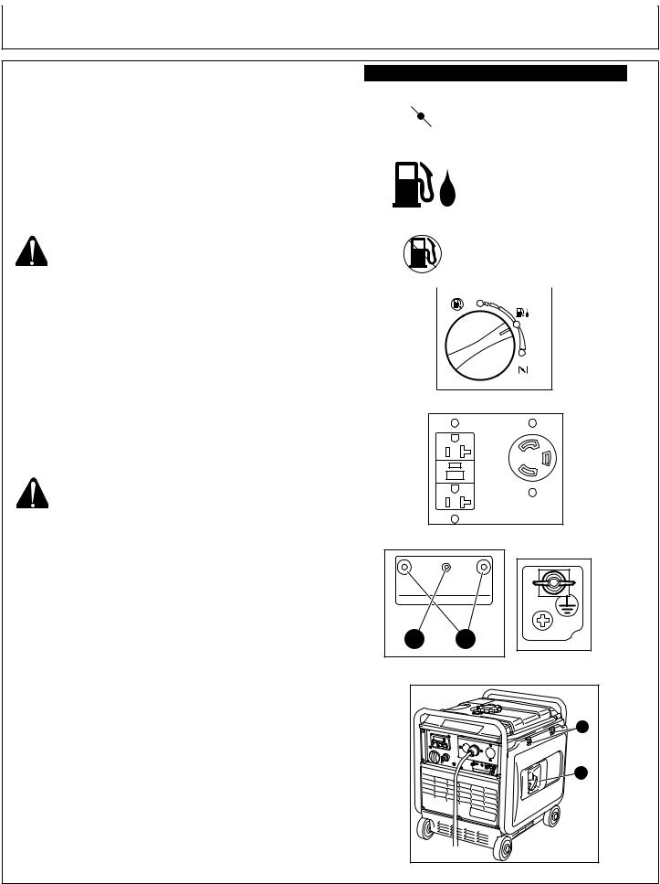
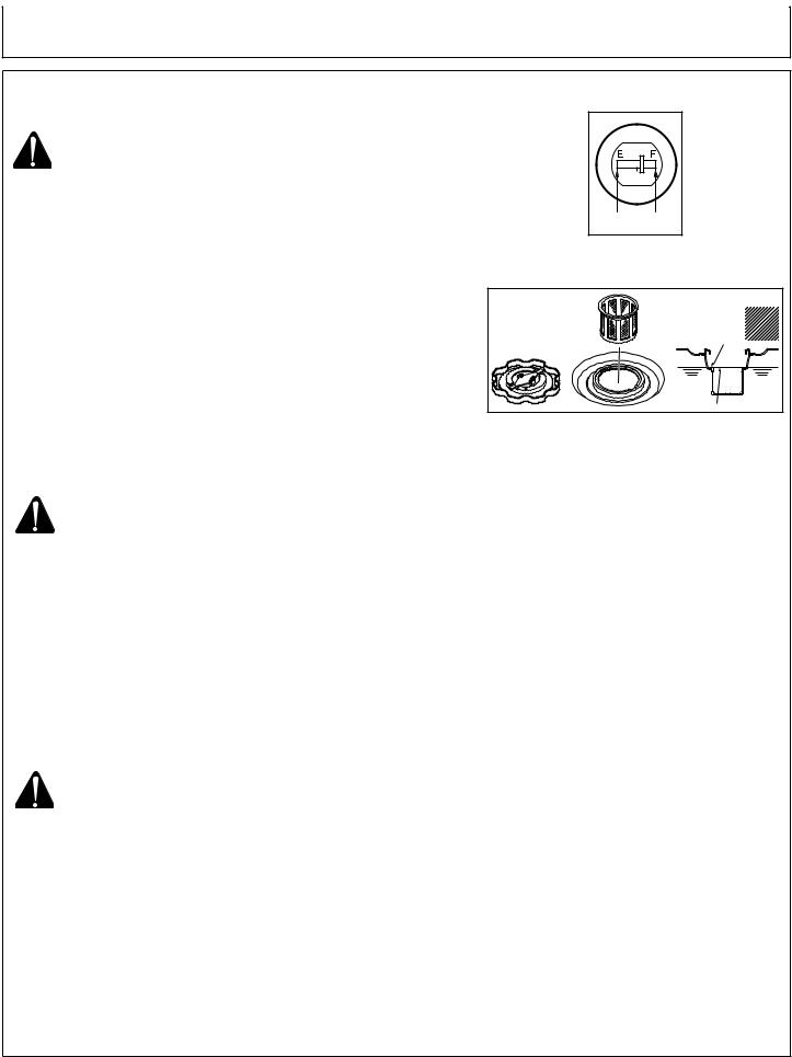
ENGINE SWITCH: (Fig. 1)
The engine switch is designed for easy operation with the interlocking mechanism between the fuel valve and the choke.
AC RECEPTACLES: (Fig. 2)
AC electric power is available through these receptacles.
-Two 20A receptacles
-One 30A receptacle
Use a grounding type plugs as shown on page 28.
WARNING: DO NOT PUT FOREIGN OBJECTS
INTO THE PLUG RECEPTACLE.
DC TERMINALS: (Fig. 3-A)
The DC terminals are used only for charging 12 voltbatteries. It provides up to 12V-8.3A (100W) of maximum power.
-Red is positive (+) terminal.
-Black is negative (-) terminal.
DC CIRCUIT BREAKER: (Fig. 3-B)
DC circuit breaker shuts off electric current when the current exceeds its limit or a malfunction occurs in the connected appliance.
Check for excessive current consumption or defects in the appliance. After making sure everything is in order, push the button to the “ON” position.
CAUTION: IF CIRCUIT BREAKER CONTINUES TOTRIP,CHECKAPPLIANCEFOR DEFECT. IF GENERATOR IS MALFUNCTIONING, SEE YOUR AUTHORIZED JOHN DEERE SERVICE CENTER OR DEALER.
NEVERINTERFEREWITHTHEOPERATION
OF THE CIRCUIT BREAKER KNOB OR
KEEP PUSHING IT IN THE “ON”
POSITION.
GROUND TERMINAL: (Fig. 4)
Terminal for grounding the generator.
RECOIL STARTER: (Fig. 5-A)
Pull this handle to start the generator.
SIDE COVER: (Fig. 5-B)
To access the following items for servicing, take the applicable side cover out by removing the screw with a screwdriver.
LH-Side Cover - Oil Level Gauge, Air Cleaner,
Spark Plug, Battery, etc.
RH-Side Cover - Oil Drain Plug, etc. (Recoil Side)
|
|
|
ENGINE SWITCHES |
||
CHOKE |
|
To start the engine, turn the |
|||
|
|
|
|
knob to the position. (Choke |
|
|
|
|
|
||
|
|
|
|
valve is closed.) |
|
|
|
|
|
|
|
|
|
|
|
|
|
|
RUN |
|
Keep the knob in this |
||
|
|
|
|
position after the engine |
|
|
|
|
|
starts. (The engine can be |
|
|
|
|
|
started with the knob at the |
|
|
|
|
|
position when the engine is |
|
|
|
|
|
warm. |
|
|
STOP |
|
To stop the engine, return |
||
|
|
|
|
the knob to the position. |
|
|
|
|
|
(The fuel cock is closed as |
|
|
|
|
|
well.) |
|
|
|
|
|
|
|
|
|
|
|
||
|
|
|
STOP |
|
|
|
|
|
|
RUN |
|
CHOKE
(Fig. 1)
(Fig. 2)
B |
A |
|
|
(Fig. 3) |
(Fig. 4) |
|
|
B |
|
|
A |
(Fig. 5)
18 |
Operator’s Manual |
Controls
CONTROLS
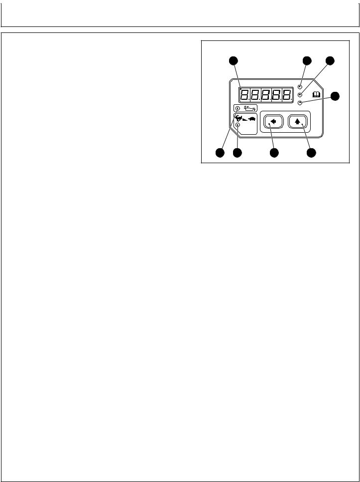
MULTI MONITOR: (Fig. 6)
LED Screen: (A)
Operation hour, voltage and frequency are indicated in turn by means of depressing the LED screen changeover switch. In addition, “O_Lod” (overload) will be indicated when the generator is in the overload condition or appliances(s) will be out of order.
In this case, stop the engine immediately and check the appliance and/or generator for overloading.After the check and remedy, restarting the engine will resume displaying in the normal manner.
Oil Sensor Lamp: (B)
When the level of the engine oil falls below the prescribed value, the alarm lamp lights up and the engine stops automatically. When the engine stops due to oil shortage, it can not be started anymore even by pulling the recoil starter (just the alarm lamp flickers). In such a case, replenish engine oil. See “Pre-Operation; Engine Oil” on page 21.
Auto Power Save Lamp: (C)
Lamp (green) is turned on while auto-power saving function is activated.
Auto Power Save Switch: (D)
When depressing the switch, auto-power saving function is activated. The engine speed is reduced automatically when no load is applied, while the engine speed is automatically increased when the load is applied.
When using DC power, turn the auto-power saving switch off.
LED Screen Changeover Lamp: (E)
When depressing this switch, indication in LED screen is changed over in turns:
operation hour  voltage
  frequency
  operation hour
When starting the engine, operation hour is indicated in LED screen at first.
Frequency Lamp: (F)
Lamp (red) is turned on when changing over into frequency indication in the LED screen.
Voltage Lamp: (G)
Lamp (red) is turned on when changing over into voltage indication in the LED screen.
Operation Hour Lamp: (H)
Lamp (red) is turned on when changing over into operation hour indication in the LED screen.
MULTI MONITOR |
|
|
||
|
A |
|
H |
G |
|
|
MULTI MONITOR |
Hours |
|
|
|
|
|
|
|
|
|
V |
F |
|
|
|
Hz |
|
|
|
AUTO |
|
|
|
|
P-SAVE |
|
|
B |
C |
D |
E |
|
(Fig. 6)
Operator’s Manual |
19 |
Preparing the Generator
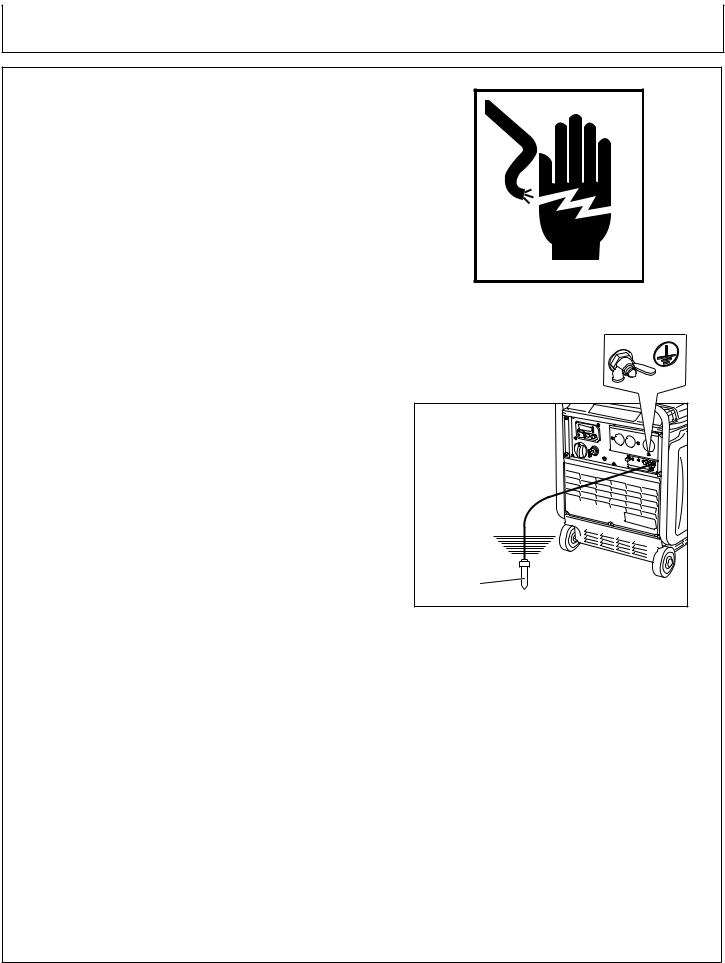
GROUNDING INSTRUCTIONS
This product must be grounded. If it should malfunction or breakdown, grounding provides a path of least resistance for electric current to reduce the risk of electric shock.
DANGER - IMPROPER CONNECTION OF THE EQUIPMENT-GROUNDING CONDUCTOR CAN RESULT IN A RISK OF ELECTROCUTION.
CHECK WITH A QUALIFIED ELECTRICIAN OR SERVICE PERSON IF YOU ARE IN DOUBT AS TO WHETHER THE UNIT IS PROPERLY GROUNDED.
The ground terminal on the frame must always be used to connect the generator to a suitable ground source. The ground path should be made with #8 size wire. Connect the grounding wire securely to the ground terminal. Connect the other end of the wire securely to a suitable ground source. (Fig. 1)
The National Electric Code contains several practical ways in which to establish a good ground source. Examples given below illustrate a few of the ways in which a good ground source may be established.
A metal underground water pipe in direct contact with the earth for at least 10 feet can be used as a grounding source. If an pipe is unavailable, an 8 foot length of pipe or rod may be used as the ground source. The pipe should be 3/4 inch trade size or larger and the outer surface must be noncorrosive. If a steel or iron rod is used it should be at least 5/8 inch diameter and if a nonferrous rod is used it should be at least 1/2 inch diameter and be listed as material for grounding. Drive the rod or pipe to a depth of 8 feet. If a rock bottom is encountered less than 4 feet down, bury the rod or pipe in a trench. All electrical tools and appliances operated from this generator, must be properly grounded by use of a third wire or be “Double Insulated”.
It is recommended to:
1.Use electrical devices with 3 prong power cords.
2.Use an extension cord with a 3 hole receptacle and a 3 prong plug at the opposite ends to ensure continuity of the ground protection from the generator to appliance.
We strongly recommend that all applicable federal, state and local regulations relating to grounding specifications be checked and followed.
LINE TRANSFER SWITCH
If this generator is used for standby service, it must have a transfer switch between the utility power service and the generator. The transfer switch not only prevents the utility
power form feeding into the generator, but is also prevents the generator form feeding out into the utility company’s lines. This is intended to protect the serviceman who may be working on a damaged line.
THIS INSTALLATION MUST BE DONE BY A LICENSED ELECTRICIAN AND ALL LOCAL CODES MUST BE FOLLOWED.
Grounding Rod |
(Fig. 1)
20 |
Operator’s Manual |
Preparing the Generator
PRE-OPERATION
ENGINE OIL:
Before checking or refilling oil, be sure generator is located on stable and level surface with engine stopped.
1.Remove oil dipstick and check the engine oil level. (Fig. 2)
2.If oil level is below the lower level line, refill with suitable oil to upper level line. Do not screw in the oil dipstick when checking oil level. (Fig. 3)
3.Change oil if contaminated. (See “Maintenance Schedule; Changing Engine Oil” page 36)
Oil Capacity: |
|
AC-G3200i ......................... |
20.5 oz. / 0.6 qt. / 0.6 liters |
AC-G4300i ......................... |
33.3 oz. / 1.0 qt. / 1.0 liters |
Recommended engine oil:
John Deere PLUS-4® oil is the preferred oil to use. If John Deere PLUS-4® oil is not available, use 4-stroke automotive detergent oil of API service class SE or higher grade (SG, SH or SJ is recommended). If single viscosity oil is used, select the appropriate viscosity for the average temperature in your area. (Fig. 4)
Engine Oil Dipstick |
(Fig. 2)
(Fig. 3)
(Fig. 4)
Operator’s Manual |
21 |
Preparing the Generator
PRE-OPERATION
FUELING:
WARNING: WARNING: EXPLOSIVE FUEL! GASOLINE IS EXTREMELY FLAMMABLEAND ITS VAPORS CAN EXPLODE IF IGNITED.
DONOTREFUELWHILESMOKINGORNEAROPEN FLAME OR OTHER SUCH POTENTIAL FIRE HAZARDS.
STORE GASOLINE ONLY IN APPROVED
CONTAINERS, IN WELL VENTILATED,
UNOCCUPIED BUILDINGS AND AWAY FROM
SPARKS OR FLAMES.
DO NOT FILL THE FUEL TANK WHILE THE ENGINE IS HOT OR RUNNING, SINCE SPILLED FUEL COULD IGNITE IF IT COMES IN CONTACT WITH HOT PARTS OR SPARKS FROM IGNITION. DO NOT START THE ENGINE NEAR SPILLED FUEL.
NEVER USE GASOLINE AS A CLEANING AGENT.
WARNING: DO NOT OVERFILL THE FUEL TANK, LEAVE ROOM FOR THE FUEL TO EXPAND.
1.If fuel level is low, refill with unleaded automotive gasoline.
2.Check fuel gauge while filling. (Fig. 5)
3.Be sure to use the fuel filter screen on the fuel filter neck. (Fig. 6) Fuel Tank Capacity:
AC-G3200i ...................... 2.9 gal. / 10.8 liters AC-G4300i ...................... 3.4 gal. / 12.8 liters
Empty Full
(Fig. 5)
(Fig. 6)
4.When using the generator for the first time or stopping due to the fuel running out, pull the recoil handle several times after filling the tank.
WARNING: MAKE SURE YOU REVIEW EACH WARNING
IN ORDER TO PREVENT FIRE HAZARD.
DO NOT REFILLTANK WHILE ENGINE IS RUNNING OR HOT.
BEFORE FILLING FUEL, TURN THE ENGINE SWITCH TO “  “ (STOP) POSITION.
BE CAREFUL NOT TO ADMIT DUST, DIRT, WATER OR OTHER FOREIGN OBJECTS INTO FUEL.
WIPE OFF SPILT FUEL THOROUGHLY BEFORE STARTING ENGINE.
KEEP OPEN FLAMES AWAY.
22 |
Operator’s Manual |

Preparing the Generator
PRE-OPERATION
FUELING (continued):
General Recommendations
•Purchase gasoline in small quantities and store in clean, approved containers.
•To minimize gum deposits in your fuel system and to insure easy starting, do not use gasoline left over from the previous season.
•Do not add oil to the gasoline.
Fuel Type
•For best results use only clean, fresh, unleaded gasoline with a pump sticker octane rating of 87 or higher.
•Unleaded gasoline is recommended as it leaves less combustion chamber deposits.
GASOLINE/ALCOHOL BLENDS:
Gasohol (up to 10% ethyl alcohol, 90% unleaded gasoline by volume) is approved, as a fuel. Other gasoline/alcohol blends are not approved.
GASOLINE/ETHER BLENDS:
Methyl Tertiary Butyl Ether (MTBE) and unleaded gasoline blends (up to a maximum of 15% MTBE by volume) are approved as a fuel. Other gasoline/ether blends are not approved.
Operator’s Manual |
23 |
Preparing the Generator
PRE-OPERATION
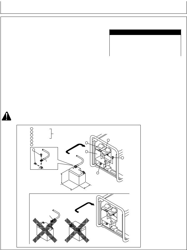
BATTERY INSTALLATION:
1.Attach terminals to a lead-acid battery already charged. Mount the battery onto the position as specified below, with its terminals facing inward.
2.Insert each long bolt through the specified hole, its tip pointing outward.
3.Put the supporting arm on the long bolts and tighten with the butterfly nuts. (Push the lead-acid battery all the way inward.)
4.Arrange the wiring so that it won’t be damaged by possible vibration caused by the engine.
5.Only after checking that the engine’s starter key in the “OFF” position, securely connect the red cable, to the positive (+) terminal. And then connect the other cable to the negative (-) terminal.
Red Cable: to the (+) terminal Black Cable: to the (-) terminal
RECOMMENDED BATTERY
LEAD-ACID BATTERY
|
AC-G3200i |
AC-G4300i |
USA |
SW7L-BS |
SW12AL-A |
CANADA |
SWC7L-BS |
SWC12AL-A |
CAUTION: ENGINE DAMAGE WILLOCCUR IF THE TERMINALCONNECTIONS
ARE CONNECTED IN THE INCORRECT MANNER.
1 |
Battery Base |
|
|
2 |
Flange Bolt |
Accessory parts |
|
3 |
Screw |
|
|
|
|
||
4 |
Battery Band |
|
4 |
5 |
Bolt and Nut |
|
|
|
6 |
||
6 |
Battery cover |
|
|
|
|
||
|
5 |
|
1 |
|
|
|
|
|
|
|
3 |
|
RED |
|
|
|
CABLE |
|
|
LESS THAN |
|
2 |
|
|
|
||
131 mm [5.2 in.] (AC-G3200i) |
|
||
162 mm [6.4 in.] (AC-G4300i) |
|
||
LESS THAN |
|
LESS THAN |
|
114 mm [4.5 in.] (AC-G3200i) |
71 mm [2.8 in.] (AC-G3200i) |
||
136 mm [5.4 in.] (AC-G4300i) |
82 mm [3.2 in.] (AC-G4300i) |
||
|
RED CABLE |
|
|
24 |
Operator’s Manual |

Preparing the Generator
PRE-OPERATION
CHECK COMPONENT PARTS:
Check following items before starting engine:
1.Fuel leakage from fuel hose, etc.
2.Bolts and nuts for looseness.
3.Components for damage or breakage.
4.Generator not resting on or against any adjacent wiring.
CHECK GENERATOR SURROUNDINGS:
When listening to the radio near the generator, the radio sound may be disturbed on account of the radio wave condition and the radio performance.
Make sure you review each warning in order to prevent fire hazard.
WARNING: KEEP AREA CLEAR OF FLAMMABLES OR OTHER HAZARDOUS MATERIALS.
KEEP GENERATOR AT LEAST 3 FEET (1 METER) AWAY FROM BUILDINGS OR OTHER STRUCTURES.
ONLY OPERATE GENERATOR INADRY, WELL VENTILATED AREA.
KEEP EXHAUST PIPE CLEAR OF FOREIGN OBJECTS.
KEEP GENERATOR AWAY FROM OPEN FLAME.
NO SMOKING!
KEEP GENERATOR ON A STABLE AND LEVEL SURFACE.
DO NOT BLOCK GENERATOR AIR VENTS WITH PAPER OR OTHER MATERIAL.
Operator’s Manual |
25 |
Operation
OPERATION
Recoil Start
CAUTION: CHECK THE OIL LEVEL BEFORE EACH
OPERATION AS OUTLINED ON PAGE 21.
WHEN STARTING THE ENGINE WITH THE RECOIL START, SET THE KEY SWITCH AT THE “ I “ (ON) POSITION BEFORE PULLING THE STARTER HANDLE.
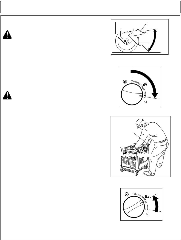
NOTE:Read Operator’s Manual carefully before operating this unit. Always be sure to place the generator on a level surface, locking the wheel with the brake and/or blocking the wheels. (Fig. 7)
1.Make sure all appliances are disconnected from the generator.
2.Turn engine switch to the “ 

 “ (CHOKE) position (Fig. 8). (When the engine is warm or temperature is high, start engine with the switch at “
 “ (RUN) position).
CAUTION: DO NOT CONNECT APPLIANCES WITH DEFECTIVE LINES AND/OR PLUGS.
BE SURE APPLIANCES ARE NOT CONNECTED TO GENERATOR WHEN STARTING UP. STARTING THE GENERATOR WITH AN APPLIANCE CONNECTED COULD RESULT IN DAMAGE TO THE GENERATOR AND/OR APPLIANCE AND PERSONAL INJURY.
3.Pull the recoil starter handle slowly until passing the compression point (resistance will be felt), then return the handle to its original position and pull briskly. (Fig. 9)
4.After starting, allow the recoil starter handle to return to its original position with the handle still in your hand.
NOTE: If the engine fails to start after several attempts, repeat the starting procedures mentioned above with the engine switch placed at “ 
 “ (RUN) position.
5.After 20 to 30 seconds of warm-up is completed, turn the engine switch to “ 
 “ (RUN) position. (Fig. 10)
6.Check to make sure the generator voltage is operating at normal levels by changing over the LED screen in the multi monitor into the “V” indication. Normal level is approximately 120V.
NOTE: Please contact an authorized John Deere Dealer if the multi monitor is off during the proper operation.
7.Test the GFCI receptacle on the unit. Push the test button. The reset button should pop out and there should be no power at the receptacle. Apply a test load or lamp to each receptacle to verify. IF THE RESET BUTTON DOES NOT POP OUT, DO NOT USE THE RECEPTACLE. SEE DEALER FOR SERVICE IMMEDIATELY.
8.If GFCI receptacle tests correctly, firmly push the reset button to restore power.Adistinctive click should be heard or felt when this is complete. IF THE RECEPTACLE DOES NOT RESET PROPERLY, DO NOT USE THE RECEPTACLE. SEE DEALER FOR SERVICE IMMEDIATELY.
9.Loads can now be applied to unit.
Brake |
Unlock |
Lock |
(Fig. 7)
STOP
RUN
 CHOKE
CHOKE
(Fig. 8)
Recoil Starter Handle


 Pull Briskly
(Fig. 9)
STOP
RUN
CHOKE
(Fig. 10)
26 |
Operator’s Manual |
Operating the Generator
OPERATION
Electric Start
CAUTION: CHECK THE OIL LEVEL BEFORE EACH
OPERATION AS OUTLINED ON PAGE 21.
NOTE: Read Operator’s Manual carefully before operating this unit. Always be sure to place the generator on a level surface, locking the wheel with the brake and/or blocking the wheels. (Fig. 7)
1.Make sure all appliances are disconnected from the generator.
2.Turn engine switch to the “ 

 “ (CHOKE) position (Fig. 8). (When the engine is warm or temperature is high, start engine with the switch at “
 “ (RUN) position).
3.Insert the key into the key switch and turn it clockwise to the “ I “ (ON) position to start the engine. Then turn the key further to the “  “ (START) position. The engine will started by the starting motor.
CAUTION: DO NOT CONNECT APPLIANCES WITH DEFECTIVE LINES AND/OR PLUGS.
BE SURE APPLIANCES ARE NOT CONNECTED TO GENERATOR WHEN STARTING UP. STARTING THE GENERATOR WITH AN APPLIANCE CONNECTED COULD RESULT IN DAMAGE TO THE GENERATOR AND/OR APPLIANCE AND PERSONAL INJURY.
DO NOT TURN THE STARTING MOTOR OVER 5 SECONDS CONTINUOUSLY. IF THE ENGINE FAILS TO START, RETURN THE KEY TO THE “ I “ (ON) POSITION AND WAIT ABOUT 10 SECONDS THEN START AGAIN.
DONOTTURNTHEKEYSWITCHTOTHE“ “(START) POSITION WHEN THE ENGINE IS RUNNING TO PREVENT DAMAGE OF STARTING MOTOR.
4.After 20 to 30 seconds of warm-up is completed, turn the engine switch to “ 
 “ (RUN) position. (Fig. 10)
5.Check to make sure the generator voltage is operating at normal levels by changing over the LED screen in the multi monitor into the “V” indication. Normal level is approximately 120V.
NOTE: Please contact an authorized John Deere Dealer if the multi monitor is off during the proper operation.
6.Test the GFCI receptacle on the unit. Push the test button. The reset button should pop out and there should be no power at the receptacle. Apply a test load or lamp to each receptacle to verify. IF THE RESET BUTTON DOES NOT POP OUT, DO NOT USE THE RECEPTACLE. SEE DEALER FOR SERVICE IMMEDIATELY.
7.If GFCI receptacle tests correctly, firmly push the reset button to restore power.Adistinctive click should be heard or felt when this is complete. IF THE RECEPTACLE DOES NOT RESET PROPERLY, DO NOT USE THE RECEPTACLE. SEE DEALER FOR SERVICE IMMEDIATELY.
8.Loads can now be applied to unit.
Operator’s Manual |
27 |
Operating the Generator
OPERATION
USING ELECTRIC POWER:
WARNING: MAKE SURE THAT THE APPLIANCE IS SWITCHED OFF BEFORE CONNECTING IT TO THE GENERATOR.
DO NOT MOVE THE GENERATOR WHILE IT IS RUNNING.
BE SURE TO GROUND THE GENERATOR. FAILURE TO GROUND UNIT MAY LEAD TO ELECTRICAL SHOCK.
AC APPLICATION:
1.Make sure the voltage indicated in the LED screen is the normal level (approx. 120V).
NOTE: This generator is thoroughly tested and adjusted in the factory. If the generator does not produce the specified voltage, consult your nearest authorized John Deere Dealer
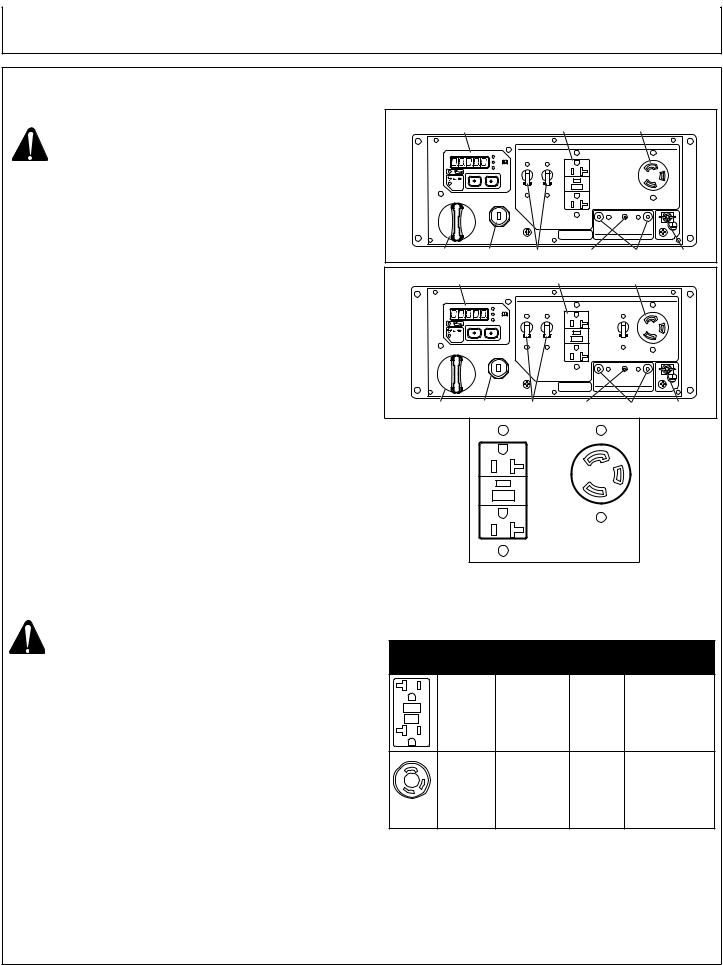
CONTROL PANELS
AC-G3200i |
|
|
|
|
Multi Monitor |
AC Receptacles (20A) |
AC Receptacles (30A) |
||
Engine Switch |
Key Switch |
AC Circuit Breaker DC Circuit Breaker |
DC Terminals |
Ground Terminal |
AC-G4300i |
Multi Monitor |
AC Receptacles (20A) |
AC Receptacles (30A) |
||
|
|||||
Engine Switch |
Key Switch |
AC Circuit Breaker DC Circuit Breaker |
DC Terminals |
Ground Terminal |
|
2.Turn off the switch(es) of the electrical appliance(s) before connecting to the generator.
3.Insert the plug(s) of the electrical appliance(s) into the receptacle. (Fig. 11)
•UsingTable 1, check the amperage of the receptacles used and be sure not to take a current exceeding the specified amperage.
•Be sure that the total wattage of all connected appliances does not exceed the rated output of the generator, see specifications on page 30.
WARNING: TO TAKE POWER OUT FROM THE TWIST LOCK RECEPTACLE, INSERT THE PLUG INTO THE RECEPTACLE, AND TURN IT CLOCKWISE TO THE LOCK POSITION.
BE SURE TO GROUND THE GENERATOR IF THE CONNECTED ELECTRICAL DEVICE IS GROUNDED.
DONOTPUTFOREIGNOBJECTSINTOTHEPLUG RECEPTACLE.
NOTE: When the “O_Lod” (overload) is indicated in the LED screen, AC output is cut off on the grounds that the generator operation is in overload condition or appliance(s) will be out of order.
Stop the generator immediately, check the appliance and/or generator for overloading, and have repaired as necessary by an authorized John Deere Dealer.
4. Turn on the switch of the appliance.
(Fig. 11)
Style |
Ampere |
Receptacle |
AC |
Description |
|
|
|
plug |
|
|
Up to |
NEMA |
NEMA |
GFCI (Ground |
|
20A |
5-20R |
5-20P |
Fault Circuit |
|
|
|
|
Interrupter) |
|
|
|
|
Receptacle, |
|
|
|
|
duplex |
|
Up to |
NEMA |
NEMA |
Locking |
|
30A |
5-30R |
5-30P |
Receptacle |
Table 1
28 |
Operator’s Manual |
Operating the Generator
OPERATION
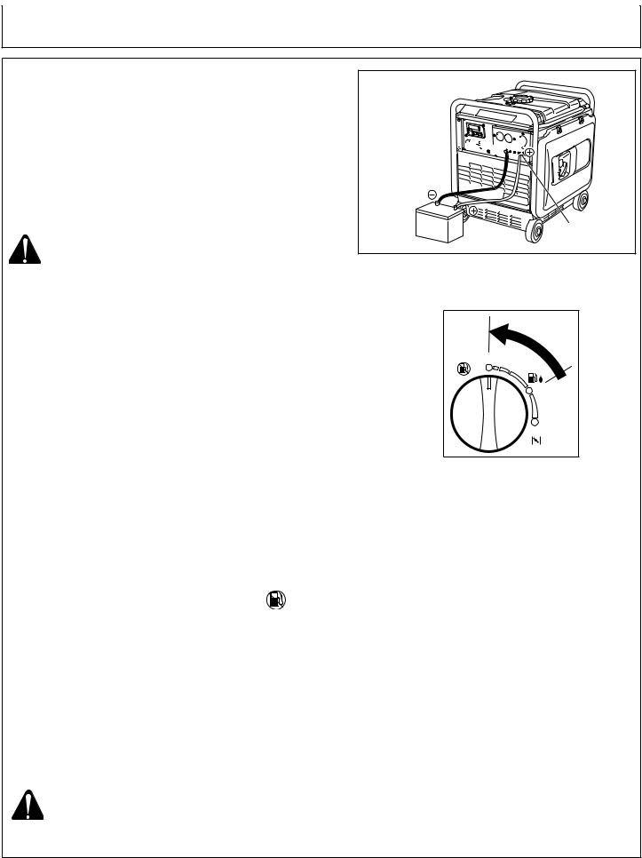
DC APPLICATION:
The DC terminal is used only for charging 12 volt batteries. It provides up to 12V - 8.3A (100W) of maximum power. (Fig. 12)
CONNECTION OF CABLE:
Connect positive terminal (red) on generator to positive (+) terminal on battery.
Connect negative terminal (black) on generator to negative (-) terminal on battery.
SAFETY PRECAUTIONS WHILE CHARGING:
WARNING: AN EXPLOSIVE HYDROGEN GAS IS DISCHARGED THROUGH VENT HOLES IN THE BATTERY DURING THE CHARGING PROCESS. DO NOT ALLOW SPARK OR OPEN FLAME AROUND THE GENERATOR OR BATTERY DURING THE CHARGING
PROCESS.
ELECTROLYTE FLUID CAN BURN EYES AND CLOTHING. BE EXTREMELY CAREFUL TO AVOID CONTACT. IF INJURED, WASH THE AFFECTED AREA IMMEDIATELY WITH LARGE QUANTITIES OF WATER AND CONSULT A DOCTOR FOR TREATMENT.
When charging a large capacity battery or totally discharged battery, excessive current may force the DC breaker to turn off. In such cases, use a battery charger to charge a large battery with AC output.
Battery defects may cause the DC breaker to trip. Check the battery before resetting the DC breaker.
STOPPING THE GENERATOR:
1. Turn off the power switch of the electric equipment and unplug the cord from receptacle of the generator.
2. Allow the engine about 3 minutes to cool down at no load before stopping.
3. Turn the engine switch to the position “ “ (STOP). (Fig. 13)
4. Turn the key switch to the “O” (STOP) position. OIL SENSOR:
The oil sensor detects the fall in oil level in the crankcase and automatically stops the engine when the oil level falls below a predetermined level.
When the engine has stopped automatically, turn off the generator, and check the oil level. Refill engine oil to the upper level as instructed on page 21 and restart the engine.
If the engine dose not start by usual starting procedures, check the oil level.
CAUTION: DO NOT REMOVE OIL SENSOR PROBE WHEN REFILLING WITH OIL.
REMOVE OIL FILLER CAP ON THE OPPOSITE SIDE OF CARBURETOR.
Negative Terminal 


 (Black)


Positive Terminal (Red)
(Fig. 12)
STOP
RUN
CHOKE
(Fig. 13)
Operator’s Manual |
29 |

Operating the Generator
OPERATION
WATTAGE INFORMATION:
Some appliances need a “surge” of energy when starting. This means that the amount of electrical power needed to start the appliance may exceed the amount needed to maintain its use.
Electrical appliances and tools normally come with a label indicating voltage, cycles / Hz, amperage (amps) and electrical power needed to run the appliance or tool.
Check with your nearest dealer or service center with questions regarding power surge of certain appliances or power tools.
•Electrical loads such as incandescent lamps and hot plates require the same wattage to start as is needed to maintain use.
•Loads such as fluorescent lamps require 1.2 to 2 times the indicated wattage during start-up.
•Loads for mercury lamps require 2 to 3 times the indicated wattage during start-up.
•Electrical motors require a large starting current. Power requirements depend on the type of motor and its use. Once enough “surge” is attained to start the motor, the appliance will require only 30% to 50% of the wattage to continue running.
•Most electrical tools require 1.2 to 3 times their wattage for running under load during use. For example, a 5000 watt generator can power a 1800 to 4000 watt electrical tool.
•Loads such as submersible pumps and air compressors require a very large force to start. They need 3 to 5 times the normal running wattage in order to start. For example, a 5000 watt generator would only be able to drive a 1000 to 7000 watt pump.
NOTE: The following wattage chart is general guide only. Refer to your specific appliance for correct wattage.
To determine the total wattage required to run a particular electrical appliance or tool, multiply the voltage figure of the appliance / tool by the amperage (amps) figure of same. The voltage and amperage (amps) information can be found on a name plate which is normally attached to electrical appliances and tools.
CAUTION: IF AN ELECTRIC MOTOR FAILS TO START OR
REACH RUNNING SPEED, TURN OFF THE
APPLIANCE OR TOOL IMMEDIATELY TO AVOID
EQUIPMENT DAMAGE. ALWAYS CHECK THE
REQUIREMENTS OF THE TOOL OR APPLIANCE
BEING USED COMPARED TO THE RATED OUTPUT
OF THE GENERATOR.
Applications |
Applicable Wattage (W) 60 Hz |
|
|
AC-G3200i |
AC-G4300i |
Incandescent Lamp, Heater |
approx. 2800 |
approx. 3800 |
Fluorescent Lamp, Electric Tool |
approx. 1400 |
approx. 1900 |
Mercury Lamp |
approx. 1000 |
approx. 1600 |
Compressor Pump |
approx. 600 |
approx. 800 |
30 |
Operator’s Manual |
 Loading...