


 Loading...
StarFire™ iTC and RTK
OPERATOR’S MANUAL
StarFire iTC™ and RTK
OMPC20964 Issue J7 (ENGLISH)
CALIFORNIA
Proposition 65 Warning
Diesel engine exhaust and some of its constituents are known to the State of California to cause cancer, birth defects, and other reproductive harm.
If this product contains a gasoline engine:
 WARNING
The engine exhaust from this product contains chemicals known to the State of California to cause cancer, birth defects or other reproductive harm.
The State of California requires the above two warnings.
John Deere Ag Management Solutions
(This manual replaces OMPC20677)
European Version
DCY
OMPC20964
Printed in Germany

Contents
Page |
Page |
Safety . . . . . . . . . . . . . . . . . . . . . . . . . . . . . . . . 05-1
StarFire iTC Receiver
StarFire iTC Receiver . . . . . . . . . . . . . . . . . . . . . 10-1
GS2 Display—StarFire iTC
STARFIRE ITC softkey. . . . . . . . . . . . . . . . . . . . 15-1 INFO tab . . . . . . . . . . . . . . . . . . . . . . . . . . . . . . 15-2 SETUP tab . . . . . . . . . . . . . . . . . . . . . . . . . . . . . 15-4 Correction Mode. . . . . . . . . . . . . . . . . . . . . . . . . 15-5 Correction Frequency . . . . . . . . . . . . . . . . . . . . . 15-5 Mount Direction . . . . . . . . . . . . . . . . . . . . . . . . . 15-5 Fore/Aft . . . . . . . . . . . . . . . . . . . . . . . . . . . . . . . 15-6 Height. . . . . . . . . . . . . . . . . . . . . . . . . . . . . . . . . 15-7 QuickStart . . . . . . . . . . . . . . . . . . . . . . . . . . . . . 15-7 Hours On After Shutdown. . . . . . . . . . . . . . . . . . 15-8 TCM Calibration . . . . . . . . . . . . . . . . . . . . . . . . . 15-8 ACTIVATIONS tab . . . . . . . . . . . . . . . . . . . . . . 15-12 SERIAL PORT tab . . . . . . . . . . . . . . . . . . . . . . 15-15 NMEA Strings. . . . . . . . . . . . . . . . . . . . . . . . . . 15-16 SATELLITE INFORMATION softkey. . . . . . . . . 15-19 Satellite Predictor . . . . . . . . . . . . . . . . . . . . . . . 15-23 DIAGNOSTIC softkey . . . . . . . . . . . . . . . . . . . . 15-24 READINGS tab. . . . . . . . . . . . . . . . . . . . . . . . . 15-25 DATA LOGS tab. . . . . . . . . . . . . . . . . . . . . . . . 15-26 Radio Self Test. . . . . . . . . . . . . . . . . . . . . . . . . 15-33 StarFire Signal Monitoring System . . . . . . . . . . 15-34
GS2 Display—RTK
RTK softkey . . . . . . . . . . . . . . . . . . . . . . . . . . . . 20-1 Vehicle . . . . . . . . . . . . . . . . . . . . . . . . . . . . . . . . 20-3 Vehicle Repeater . . . . . . . . . . . . . . . . . . . . . . . . 20-5 Quick Survey Mode . . . . . . . . . . . . . . . . . . . . . . 20-6 Absolute Base Mode . . . . . . . . . . . . . . . . . . . . . 20-6 RTK Network Configuration . . . . . . . . . . . . . . . . 20-9 Shared Base Station RTK Security. . . . . . . . . . 20-11 Shared Base Station Security—Setup . . . . . . . 20-12 RTK Vehicle Security Status. . . . . . . . . . . . . . . 20-16
Original GreenStar Display—StarFire iTC
Auto-Update . . . . . . . . . . . . . . . . . . . . . . . . . . . . 25-1
Manual Software Update . . . . . . . . . . . . . . . . . . 25-2
StarFire Receiver . . . . . . . . . . . . . . . . . . . . . . . . 25-3
SETUP-GPS-PAGE 1. . . . . . . . . . . . . . . . . . . . . 25-4
Overview: SF2/RTK Activations, SF2
Subscription . . . . . . . . . . . . . . . . . . . . . . . . . . 25-5
QuickStart Setup . . . . . . . . . . . . . . . . . . . . . . . . 25-8
TCM
Setup . . . . . . . . . . . . . . . . . . . . . . . . . . . . . . . 25-9
On/Off . . . . . . . . . . . . . . . . . . . . . . . . . . . . . . . 25-9
Mount Direction. . . . . . . . . . . . . . . . . . . . . . . 25-10
Calibrate Level . . . . . . . . . . . . . . . . . . . . . . . 25-11
Height . . . . . . . . . . . . . . . . . . . . . . . . . . . . . . 25-16
Fore/Aft. . . . . . . . . . . . . . . . . . . . . . . . . . . . . 25-17
Differential Correction Setup. . . . . . . . . . . . . . . 25-18
Serial RS232 Output . . . . . . . . . . . . . . . . . . . . 25-19
Hours On After Shutdown. . . . . . . . . . . . . . . . . 25-20
INFO - GPS - PAGE 1 . . . . . . . . . . . . . . . . . . . 25-21
INFO - GPS - PAGE 2 . . . . . . . . . . . . . . . . . . . 25-23
Data Log . . . . . . . . . . . . . . . . . . . . . . . . . . . . . 25-24
INFO - GPS - PAGE 3 . . . . . . . . . . . . . . . . . . . 25-28
Satellite Tracking . . . . . . . . . . . . . . . . . . . . . . . 25-29
Original GreenStar Display—RTK
Operating Mode . . . . . . . . . . . . . . . . . . . . . . . . . 30-1
Vehicle Repeater . . . . . . . . . . . . . . . . . . . . . . . . 30-3
Quick Survey Mode . . . . . . . . . . . . . . . . . . . . . . 30-4
Absolute Mode . . . . . . . . . . . . . . . . . . . . . . . . . . 30-5
Shared Base Station RTK Security. . . . . . . . . . . 30-8
Time Slot . . . . . . . . . . . . . . . . . . . . . . . . . . . . . 30-12
Network ID . . . . . . . . . . . . . . . . . . . . . . . . . . . . 30-13
Repeater . . . . . . . . . . . . . . . . . . . . . . . . . . . . . 30-14
Operating Vehicle . . . . . . . . . . . . . . . . . . . . . . . 30-15
RTK
Info Pages . . . . . . . . . . . . . . . . . . . . . . . . . . 30-17
Info Pages . . . . . . . . . . . . . . . . . . . . . . . . . . 30-18
RTK Base Station Setup
Country Use Restrictions . . . . . . . . . . . . . . . . . . 35-1 System Overview . . . . . . . . . . . . . . . . . . . . . . . . 35-2 Installation of the RTK radio and antenna. . . . . . 35-4 Attaching RTK Harness . . . . . . . . . . . . . . . . . . . 35-5 RTK Network Base Station Setup . . . . . . . . . . . 35-6 Multipathing . . . . . . . . . . . . . . . . . . . . . . . . . . . 35-10
Continued on next page
All information, illustrations and specifications in this manual are based on the latest information available at the time of publication. The right is reserved to make changes at any time without notice.
COPYRIGHT 2007
DEERE & COMPANY
Moline, Illinois
All rights reserved
A John Deere ILLUSTRUCTION Manual
i |
121907 |
PN=1

Contents
Page
RTK using Straight, Curves or Circle . . . . . . . . 35-16
Example A . . . . . . . . . . . . . . . . . . . . . . . . . . . . 35-17
Operating Parameters . . . . . . . . . . . . . . . . . . . 35-18
PDOP Definition . . . . . . . . . . . . . . . . . . . . . . . . 35-19
PDOP Operating Values. . . . . . . . . . . . . . . . . . 35-21
StarFire Signal Monitoring System . . . . . . . . . . 35-23
Antenna Height. . . . . . . . . . . . . . . . . . . . . . . . . 35-25
Specific Tower Setup Information . . . . . . . . . . . 35-26
Utilizing Both The 91 m (300 ft) RTK
Extension Harness And Low Loss Coax
Cable . . . . . . . . . . . . . . . . . . . . . . . . . . . . . . 35-27
Utilizing The RTK Extension Harness . . . . . . . . 35-28
Utilizing A Repeater . . . . . . . . . . . . . . . . . . . . . 35-28
Utilizing Just Low Loss Coax Cable . . . . . . . . . 35-29
Leaving The Radio And Receiver As A
Single Unit . . . . . . . . . . . . . . . . . . . . . . . . . . 35-29
Troubleshooting and Diagnostics
Accessing GREENSTAR 2 Diagnostic
Addresses. . . . . . . . . . . . . . . . . . . . . . . . . . . . 40-1
Accessing Original GREENSTAR Display
Fault Codes . . . . . . . . . . . . . . . . . . . . . . . . . . 40-3
STARFIRE iTC Diagnostic Addresses . . . . . . . . 40-4
Fault Codes—StarFire iTC . . . . . . . . . . . . . . . . . 40-8
Diagnostic Trouble Codes—StarFire iTC . . . . . 40-11
GreenStar Deluxe - Diagnostic Readings . . . . . 40-13
Specifications
Unified Inch Bolt and Screw Torque Values . . . . 45-1
Metric Bolt and Screw Torque Values. . . . . . . . . 45-2
Declaration of Conformity . . . . . . . . . . . . . . . . . . 45-3
Safety Note Regarding the Subsequent
Installation of Electrical and Electronic
Appliances and/or Components . . . . . . . . . . . 45-3
ii |
121907 |
PN=2
Safety
Recognize Safety Information
This is a safety-alert symbol. When you see this symbol on your machine or in this manual, be alert to the potential for personal injury.
Follow recommended precautions and safe operating practices.
Understand Signal Words
A signal word—DANGER, WARNING, or CAUTION—is used with the safety-alert symbol. DANGER identifies the most serious hazards.
DANGER or WARNING safety signs are located near specific hazards. General precautions are listed on CAUTION safety signs. CAUTION also calls attention to safety messages in this manual.
Follow Safety Instructions
Carefully read all safety messages in this manual and on your machine safety signs. Keep safety signs in good condition. Replace missing or damaged safety signs. Be sure new equipment components and repair parts include the current safety signs. Replacement safety signs are available from your John Deere dealer.
Learn how to operate the machine and how to use controls properly. Do not let anyone operate without instruction.
Keep your machine in proper working condition. Unauthorized modifications to the machine may impair the function and/or safety and affect machine life.
If you do not understand any part of this manual and need assistance, contact your John Deere dealer.
05-1
–UN–07DEC88 T81389 DX,ALERT –19–29SEP98–1/1
–19–30SEP88 TS187 DX,SIGNAL –19–03MAR93–1/1
TS201 –UN–23AUG88
DX,READ –19–03MAR93–1/1
121907
PN=4
Safety
Prepare for Emergencies
Be prepared if a fire starts.
Keep a first aid kit and fire extinguisher handy.
Keep emergency numbers for doctors, ambulance service, hospital, and fire department near your telephone.
Practice Safe Maintenance
Understand service procedure before doing work. Keep area clean and dry.
Never lubricate, service, or adjust machine while it is moving. Keep hands, feet , and clothing from power-driven parts. Disengage all power and operate controls to relieve pressure. Lower equipment to the ground. Stop the engine. Remove the key. Allow machine to cool.
Securely support any machine elements that must be raised for service work.
Keep all parts in good condition and properly installed. Fix damage immediately. Replace worn or broken parts. Remove any buildup of grease, oil, or debris.
On self-propelled equipment, disconnect battery ground cable (-) before making adjustments on electrical systems or welding on machine.
On towed implements, disconnect wiring harnesses from tractor before servicing electrical system components or welding on machine.
05-2
–UN–23AUG88 TS291 DX,FIRE2 –19–03MAR93–1/1
TS218 –UN–23AUG88
DX,SERV –19–17FEB99–1/1
121907
PN=5

Safety
Install and Remove StarFire Receiver and
Brackets Safely
When installing and removing the StarFire receiver, follow these guidelines to prevent potential injury from falling:
•Use an appropriate ladder or platform to easily access mounting location.
•Ensure sturdy and secure footholds and handholds.
•Avoid installing or removing receiver in wet or icy conditions.
The receiver mast used on implements is heavy and can be awkward to handle. If installing or removing a receiver mast on an implement, follow these guidelines:
•Use two people for mounting locations not accessible from the ground or a service platform.
•Use proper lifting techniques.
•Wear proper protective equipment.
05-3
PC10340 –UN–27SEP07
OUO6050,0000E4D –19–27SEP07–1/1
121907
PN=6
StarFire iTC Receiver
StarFire iTC Receiver
Receiver is located on cab of machine. It receives global positioning and differential correction signal through a single receiver and integrates signal for use with system.
Terrain Compensation Module (TCM) is integrated into receiver and is a navigational aid used with receiver to enhance vehicle position and course parameters that GPS provides. TCM corrects for vehicle dynamics such as roll on side-slopes, rough terrain or varying soil conditions.
OUO6050,0000C0C –19–18OCT07–1/4
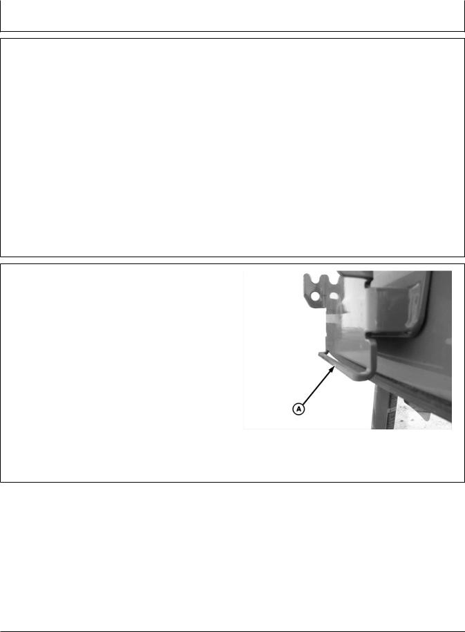
StarFire iTC Mounting Instructions
1. |
Read “Install and Remove StarFire Receiver and |
|
Brackets Safely” in the Safety section. |
2. |
Verify that vehicle side receiver bracket bar (A) is not |
|
bent inward or outward. |
|
A—Bracket Bar |
|
–UN–02SEP04 |
|
PC8328 |
Continued on next page |
OUO6050,0000C0C –19–18OCT07–2/4 |
10-1 |
121907 |
PN=7
StarFire iTC Receiver
|
–UN–31AUG04 |
|
–UN–31AUG04 |
|
PC8327 |
|
PC8329 |
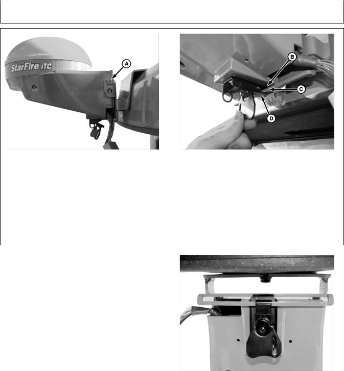
A—Mounting Peg |
B—Metal Tab |
C—Bracket Bar |
D—Receiver Latch |
3. Position StarFire iTC on bracket. Align mounting |
4. |
Position receiver latch (D) around bracket bar. Turn |
|
pegs (A) on receiver with notches in vehicle |
|
latch handle to tighten latch around bracket bar. |
|
bracket. Ensure pegs are firmly seated in notches |
|
Bracket bar should compress slightly. |
|
and metal tab (B) is above bracket bar (C). |
|
|
|
|
|
OUO6050,0000C0C |
–19–18OCT07–3/4 |
|
|
|
|
5. Fold latch handle upwards against receiver. |
|
|
|
|
|
|
–UN–31AUG04 |
|
|
|
PC8330 |
|
|
OUO6050,0000C0C |
–19–18OCT07–4/4 |
|
|
|
|
|
10-2 |
|
121907 |
PN=8
GS2 Display—StarFire iTC
STARFIRE ITC softkey
The STARFIRE ITC - MAIN screen contains four tabs:
INFO tab
SETUP tab
ACTIVATIONS tab
SERIAL PORT tab
NOTE: If StarFire iTC is hooked into the CAN Bus with an Original GreenStar display and either a GSD2100 or 2600, the StarFire iTC will always be displayed on the GSD2100 or 2600.
NOTE: If an Original StarFire receiver is hooked to a GSD2100 or 2600, the setup and information pages are displayed through Original GreenStar Monitor. MENU >> ORIGINAL GREENSTAR MONITOR. To view or change setup information, SETUP >> STARFIRE RECEIVER. To view GPS information INFO >> STARFIRE RECEIVER.
PC8663 –UN–05AUG05
MENU button
PC8659 –UN–05AUG05
STARFIRE ITC button
PC8680 –UN–05AUG05
STARFIRE ITC softkey
OUO6050,000223B –19–14NOV06–1/1
15-1 |
121907 |
PN=9
GS2 Display—StarFire iTC
INFO tab
PC9705 –UN–10NOV06
|
|
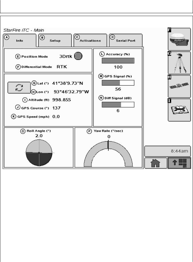
StarFire iTC - Main—Info Tab |
|
A—Info tab |
E—Position Mode |
I—Altitude |
M—GPS Signal |
B—Setup tab |
F—Differential Mode |
J—GPS Course |
N—Differential Signal |
C—Activations tab |
G—Latitude |
K—GPS Speed |
O—Roll Angle |
D—Serial Port tab |
H—Longitude |
L—Accuracy |
P—Yaw Rate |
The INFO tab shows information and status of incoming GPS and differential correction signals. No information on this screen can be changed. It is for viewing only:
•Position Mode: Indicates whether receiver is calculating a 3D position, 2D position, or no position (No Nav). It also shows status of differential signal: SF1 (StarFire 1 differential), SF2 (StarFire 2 differential).
•Differential Mode: Indicates status of GPS signal: 2-D (two dimensional with latitude and longitude of vehicle) or 3-D (three dimensional with altitude, latitude, and longitude of vehicle).
•Lat: Displays vehicle location latitude coordinates with respect to Equator (north or south).
•Lon: Displays vehicle location longitude coordinates with respect to Prim Meridian (east or west).
Continued on next page |
OUO6050,000223C –19–14NOV06–1/2 |
15-2 |
121907 |
PN=10
GS2 Display—StarFire iTC
NOTE: TOGGLE button allows operator to change the way latitude and longitude are displayed from degrees/minutes/seconds to decimal degrees.
•Altitude: displays height of receiver, measured from top of dome, in feet (meters) above sea level.
•GPS course: Displays direction of travel, in degrees relative to true north (zero degrees) as measured by receiver. Angle is measured in clockwise direction
NOTE: Course and speed normally show small speeds and various courses even when machine is not moving.
•GPS speed: displays ground speed of machine in miles per hour (kilometer per hour) as measured by receiver.
•GPS Accuracy Indicator (GPS AI): GPS AI gives indication of GPS position accuracy achieved by receiver, and is displayed as a percentage (0-100%)
When receiver is initially powered, GPS AI will display 0%. As receiver acquires satellites and calculates a position, GPS AI will increase as accuracy improves. Acceptable guidance performance for Parallel Tracking and AutoTrac is achieved when GPS AI displays 80% or greater. This may take up to 20 minutes. GPS accuracy is affected by many factors. If 80% accuracy or greater is not achieved within 25 minutes, consider the following possibilities:
•Unobstructed view of sky – trees, buildings, or other structures may block receiver from receiver signals from all available satellites.
•L1/L2 signal to noise ratio (SNR) – radio interference from 2-way radios or other sources may cause low SNR (check satellite button – Graph)
•Satellite position in sky – poor GPS satellite geometry can reduce accuracy (check satellite button – SkyPlot)
•Number of satellites above elevation mask – this is the total number of GPS satellites available to receiver that are above 7 degrees elevation mask (check satellite button – SkyPlot).
•Number of satellites in solution – this is total number of satellites that are being used by receiver to calculate a position (check satellite button– SkyPlot).
•GPS Signal Quality: Displays quality of signals being received from constellation of GPS satellites.
•Differential Signal Quality: Displays quality of differential correction signal being received by receiver.
•TCM (Terrain Compensation Module):
–Roll Angle: Is both a graphical and numerical representation of amount of roll TCM is measuring, relative to calibrated zero degree reference. A positive roll angle means vehicle is rolled to right (depicts what horizon would look like from cab).
–Yaw Rate: This gives a graphic representation and a numeric figure for amount of rotation TCM is measuring. Positive yaw rate means vehicle is turning to right.
OUO6050,000223C –19–14NOV06–2/2
15-3 |
121907 |
PN=11
GS2 Display—StarFire iTC
SETUP tab
PC9706 –UN–17OCT07
|
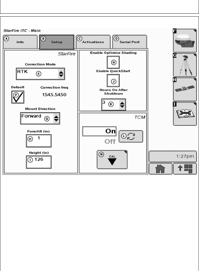
StarFire iTC - Main—Setup tab |
|
|
A—Info tab |
E—Correction Mode |
H—Fore/Aft |
K—Hours On After Shutdown |
B—Setup tab |
F—Default Correction |
I—Height |
L—TCM On/Off toggle button |
C—Activations tab |
Frequency |
J—Enable QuickStart |
M—TCM Calibration button |
D—Serial Port tab |
G—Mount Direction |
|
|
The SETUP tab allows for setup of the following:
•Correction Mode
•Correction Frequency
•Mount Direction
•Fore/Aft
•Height
•QuickStart
•Hours ON After Shutdown
•TCM Calibration
Differential correction is the process by which GPS accuracy is improved. (See OVERVIEW: SF1/SF2 Activations, SF2 Subscription under Activations section.)
OUO6050,000223D |
–19–14NOV06–1/1 |
15-4 |
121907 |
PN=12

GS2 Display—StarFire iTC
Correction Mode |
|
|
|
Contains available StarFire corrections that the |
NOTE: By selecting OFF, StarFire receiver will not |
||
receiver is licensed for. SF1 and OFF will always |
|
receive SF1 or SF2 correction signals, but will |
|
appear, however, SF2 will only appear with a valid |
|
receive WAAS/EGNOS correction signals. |
|
SF2 license (See Activations section). RTK appears |
|
|
|
when a RTK mode is selected from RTK softkey. |
|
|
|
|
|
OUO6050,000223E |
–19–14NOV06–1/1 |
|
|
|
|
Correction Frequency |
|
|
|
This is the frequency that is used to receive differential |
IMPORTANT: DO NOT change default StarFire |
||
correction signals. The default frequency is a view only |
|
Correction Frequency unless |
|
field when default check box is checked. By |
|
instructed to do so by a John Deere |
|
de-selecting default check box a correction frequency |
|
Dealer or by John Deere AG |
|
can be manually entered. |
|
Management Solutions. |
|
|
|
OUO6050,000223F |
–19–14NOV06–1/1 |
|
|
|
|
Mount Direction |
|
|
|
NOTE: Receivers attached to tractors, sprayer, and |
Mounting direction options |
|
|
combines are typically in FORWARD position. |
• |
|
|
Receivers attached to GATORS are typically in |
FORWARD |
|
|
BACKWARD position. |
• |
BACKWARD |
|
Mounting direction is direction receiver is facing. |
Select desired mounting direction. |
|
|
This setting defines mounting orientation of receiver. |
|
|
|
TCM uses this setting to determine correct direction of |
|
|
|
vehicle roll. |
|
|
|
|
|
OUO6050,0002240 |
–19–14NOV06–1/1 |
|
|
|
|
15-5 |
|
|
121907 |
PN=13
GS2 Display—StarFire iTC
Fore/Aft
PC8278 –UN–22JUN04
Floating Front Axle Vehicles
A—Pivot Point—Floating Front
Axle Vehicles-
PC8277 –UN–01MAY06
Fixed Axis Wheels or Tracks Vehicles
B—Pivot Point—-Fixed Axis
Wheels or Tracks Vehicles
The fore/aft value is the distance that receiver is located from pivot point of tractor.
On some AutoTrac-equipped vehicles, fore/aft value will be automatically detected and entered during power up.
•Fore/Aft value is shown and input box is disabled – value has been automatically set and cannot be changed. The value shown may not be the exact distance that the receiver is located from pivot point of tractor, but the best Fore/Aft value for AutoTrac.
•Fore/Aft value is shown and input box is enabled – value must be entered manually.
To enter Fore/Aft value:
• Select FORE/AFT input box
• Enter value using numeric keypad
Recommended StarFire Fore/Aft values For John Deere
Vehicles |
|
|
John Deere Vehicle |
StarFire Fore/Aft cm (in.) |
|
|
|
|
6000 |
Series Tractors |
180 cm (71 in.) |
|
|
|
7000 |
Series Tractors |
210 cm (82.5 in.) |
|
|
|
8000 |
Series Tractors |
210 cm (82.5 in.) |
|
|
|
8000T Series Tractors |
51 cm (20 in.) |
|
|
|
|
9000 |
Series Tractors |
-51 cm (-20 in.) |
|
|
|
9000T Series Tractors |
51 cm (20 in.) |
|
|
|
|
4700 |
Series Sprayers |
280 cm (110 in.) |
|
|
|
4900 |
Series Sprayers |
460 cm (181 in.) |
|
|
|
Combine |
220 cm (87 in.) |
|
|
|
|
Forage Harvester |
157 cm (62 in.) |
|
|
|
|
OUO6050,0002241 |
–19–25NOV06–1/1 |
15-6 |
121907 |
PN=14

GS2 Display—StarFire iTC
Height
Height is measured from ground to top of StarFire Dome. Select input box and use numeric keypad to enter height.
IMPORTANT: Under or over compensation for vehicle roll angles will occur if height is incorrectly entered during setup.
Example: On a 10 degree slope with a StarFire height error of 30.5 cm (12 in.) will result in a position offset of 5 cm (2 in.) on ground).
Factory default setting is “126”. On some AutoTrac-equipped vehicles, height value will be automatically detected and entered during power up. Because this dimension is critical for proper operation of TCM and can vary due to vehicle configuration and tire sizes, operator should still measure actual distance
to be entered each time TCM is installed on a different vehicle.
NOTE: Use chart for example StarFire Height values.
Chart figures are approximate heights.
John Deere Vehicle |
StarFire Height cm (in.) |
|
|
|
|
6000 |
Series Tractors |
280 cm (111 in.) |
|
|
|
7000 |
Series Tractors |
305 cm (120 in.) |
|
|
|
8000 |
Series Tractors |
320 cm (126 in.) |
|
|
|
8000T Series Tractors |
320 cm (126 in.) |
|
|
|
|
9000 |
Series Tractors |
361 cm (142 in.) |
|
|
|
9000T Series Tractors |
356 cm (140 in.) |
|
|
|
|
4700 |
Series Sprayers |
389 cm (153 in.) |
|
|
|
4900 |
Series Sprayers |
396 cm (156 in.) |
|
|
|
Combine |
396 cm (156 in.) |
|
|
|
|
NOTE: Actual height may vary depending on tire size or inflation.
|
OUO6050,0002242 –19–14NOV06–1/1 |
|
|
QuickStart |
|
Reduces amount of time required before full accuracy |
position will be used to bypass startup warm up period |
is achieved. If QuickStart is enabled (check box |
that is usually required. Receiver cannot move while |
checked) and receiver has SF1 or SF2 when it is |
this QuickStart is taking place. It may take up to 6 |
powered down a position is saved for future |
minutes for QuickStart to complete. User will be |
QuickStart. If power is restored to receiver within time |
notified on screen when it is done. |
period defined under Hours On After Shutdown, |
|
QuickStart won’t be needed since receiver power was |
To enable QuickStart mode select check box so that a |
never disrupted. If duration has exceeded Hours On |
check appears. To disable, select check box until |
After Shutdown, QuickStart will be initiated. Saved |
check disappears. |
|
OUO6050,0002243 –19–14NOV06–1/1 |
15-7 |
121907 |
PN=15
GS2 Display—StarFire iTC
Hours On After Shutdown
Defines how long receiver remains powered up after ignition is turned off (0, 3, 6, 12, 24 hours). If ignition is turned on within number of hours defined, receiver will re-establish full SF1 or SF2 accuracy within a few seconds (assuming it had SF1 or SF2 when ignition was turned off).
Define desired number of hours by selecting drop-down box.
OUO6050,0002244 –19–14NOV06–1/1
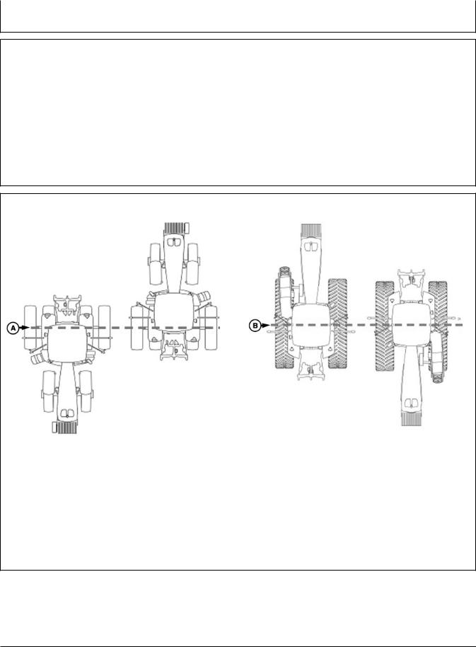
TCM Calibration
PC8278 –UN–22JUN04
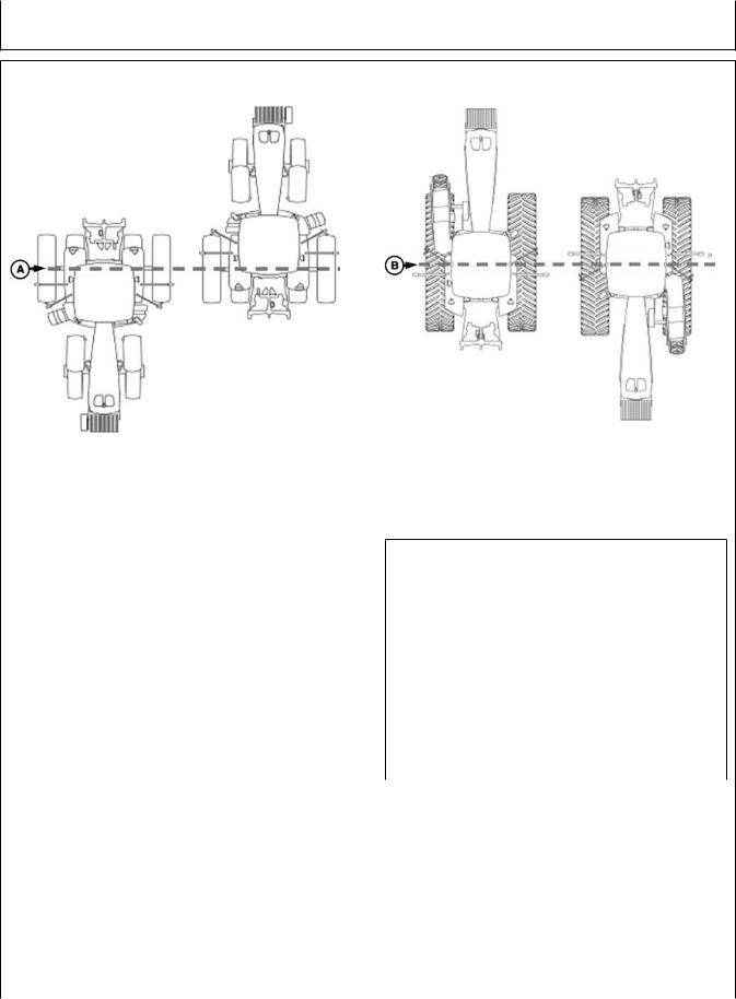
Floating Front Axle Vehicles
A—Rear Axle
PC8277 –UN–01MAY06
Fixed-Axis Wheels Or Tracks Vehicles
B—Vehicle Pivot Point
TCM can be toggled ON or OFF by selecting TOGGLE button. When TCM is turned off, StarFire GPS message will not be corrected for vehicle dynamics or side slopes. TCM will default to ON when cycling power.
NOTE: TCM must be turned on for AutoTrac to activate.
TCM must be calibrated so receiver can determine zero degree roll angle.
Continued on next page |
OUO6050,0002245 –19–14NOV06–1/4 |
15-8 |
121907 |
PN=16

GS2 Display—StarFire iTC
NOTE: Calibrate receiver when it is attached or |
location of tires on ground. When |
|
reattached to machine. Receiver does not |
turning around use following |
|
require recalibration until removed from |
instructions: |
|
machine and reattached. |
• |
|
|
Floating Front Axle Vehicles |
|
Positioning Machine during Calibration |
|
(MFWD, ILS, TLS)—put rear |
|
|
axle/wheels in same location when |
IMPORTANT: When calibrating, it is important that |
|
performing 2 point calibration. See |
TCM is at same angle when facing |
|
above diagram for Floating Front |
either direction. If roll angle is a |
• |
Axle Vehicles. |
positive 2 degrees when facing one |
Fixed-Axis Wheels Or Tracks |
|
direction, vehicle needs to be a |
|
Vehicles (Track Tractors, 47X0 and |
negative 2 degrees when facing |
|
49X0 Series Sprayers, 9000, And |
opposite direction. To position TCM |
|
9020 Series Wheel Tractors)— |
at same angle it is important when |
|
Place all in same location when |
turning vehicle around and facing |
|
facing either direction. See above |
other direction that tires are placed |
|
diagram for Fixed-Axis Wheels Or |
in correct location. Once vehicle is |
|
Tracks Vehicles. |
parked on a hard flat surface, note |
|
|
Continued on next page |
|
OUO6050,0002245 –19–14NOV06–2/4 |
15-9 |
121907 |
PN=17

GS2 Display—StarFire iTC
Calibration Surface
IMPORTANT: Vehicle must be on a hard, flat level
surface for calibration. If TCM is not |
|
|
calibrated on a level surface or TCM |
|
|
mounting angle is not level in relation |
|
|
to vehicle angle (StarFire mounting |
|
|
bracket or vehicle cab being slightly |
|
|
offset, uneven tire pressures from one |
|
|
side to other, etc.) operator may see |
|
|
offset during operation. This offset |
|
|
could look like a consistent skip (A) or |
A—Skip |
|
overlap (B) in pass-to-pass operation. |
||
B—Overlap |
||
To eliminate offset, re-calibrate on a |
|
|
level surface, drive down a pass, turn |
|
|
around and drive down same pass in |
|
|
opposite direction. If vehicle does not |
|
|
follow same pass, measure offset |
|
|
distance and enter in implement offset. |
|
|
After initial calibration of TCM, it is not |
|
|
necessary to calibrate again unless |
|
|
TCM angle in relation to vehicle has |
|
|
changed. For example, tire pressure has |
|
|
been lowered on one side of vehicle |
|
|
causing vehicle angle in relation to |
|
|
ground to change. |
|
Calibration Procedure:
1.Press CALIBRATION button.
2.Park vehicle on a hard, level surface and come to a complete stop (cab is not rocking).
3.Press ENTER button.
4.Calibrating Status bar will appear. Once status reaches 100% it will automatically advance.
5.Turn vehicle 180 degrees to face opposite direction. Ensure that tires are in proper location for fixed or floating front axle and vehicle has come to a complete stop (cab is not rocking).
6.Press ENTER CALIBRATION button.
7.Calibrating Status bar will appear. Once status reaches 100% it will automatically advance.
8.Once finished, a calibration value will be displayed. 0 degree calibration value is the difference between factory calibration value and actual calibration value which was just determined.
PC8279 –UN–16JUL04
Continued on next page |
OUO6050,0002245 –19–14NOV06–3/4 |
15-10 |
121907 |
PN=18

GS2 Display—StarFire iTC
9. Press ENTER button to return to SETUP tab.
OUO6050,0002245 –19–14NOV06–4/4
15-11 |
121907 |
PN=19
GS2 Display—StarFire iTC
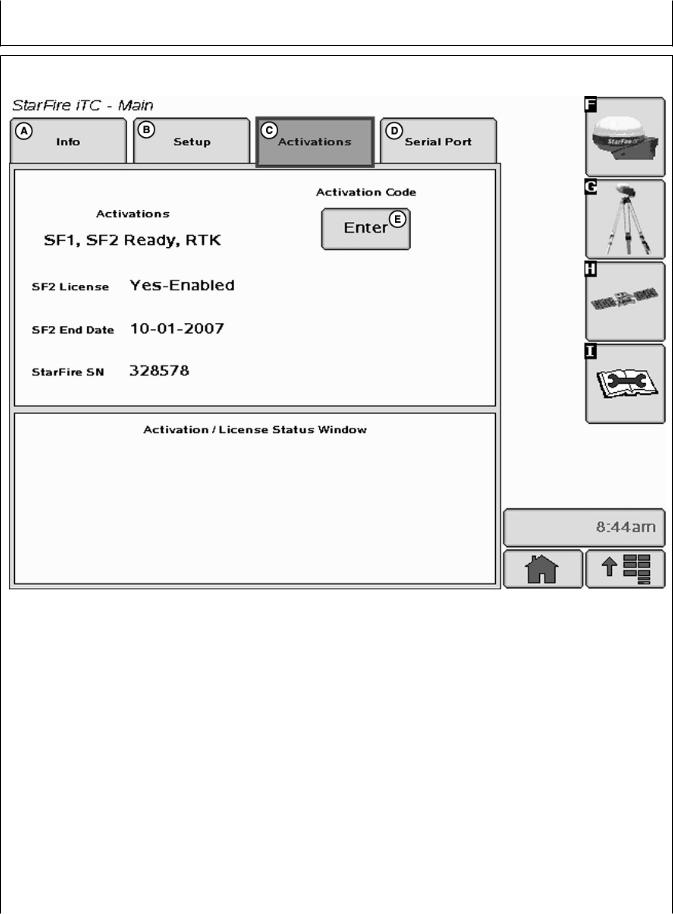
ACTIVATIONS tab
PC9707 –UN–10NOV06
|
StarFire iTC - Main—Activations tab |
|
|
A—Info tab |
C—Activations tab |
D—Serial Port tab |
E—Activation Code Enter |
B—Setup tab |
|
|
button |
ACTIVATIONS tab contains the following:
•Valid activations for receiver:
–SF1 – activated on every StarFire iTC.
–SF2 Ready – receiver has to be ordered SF2 Ready or an upgrade to SF2 ready from SF1 World Solution must be purchased.
–RTK – activated with valid RTK activation (requires receiver to be SF2 Ready).
•SF2 License: Displays status of receiver’s SF2 License.
–Yes-Enabled – A valid SF2 license exists and SF2 is the differential correction mode selected.
–Yes-Disabled – A valid SF2 license exists, but SF2 is not the differential correction mode selected.
–No – Appears when no valid SF2 license exists or SF2 license has expired.
•SF2 End Date: Displays date at which SF2 License will expire.
•StarFire SN: StarFire serial number
Continued on next page |
OUO6050,0002246 –19–14NOV06–1/3 |
15-12 |
121907 |
PN=20
GS2 Display—StarFire iTC
Activation Code
NOTE: Activation Codes are needed to obtain SF2 Ready and RTK Activations, and SF2 license subscription.
ENTER button is used to enter 24-digit codes for SF2 Ready and RTK Activations, SF2 license subscription and deactivation codes for transferring all StarFire activations and licenses mentioned above.
1.Upon selecting ENTER button an Activation Code box appears with three input boxes.
NOTE: If more than 8 digits are entered into an input box, “99999999” will appear. Reselect box and type only 8 digits into input box.
2.Select first input box labeled Digits 1-8 and enter first 8 digits of 24-digit code.
3.Select second input box labeled Digits 9-16 and enter second 8 digits of 24-digit code.
4.Select third input box labeled Digits 17-24 and enter last 8 digits of 24 digit code.
5.Press ENTER button.
6.If 24-digit code is valid and entered correctly a confirmation message will appear.
7.Deactivation Code input
This input will only appear when a deactivation code has been entered following procedure listed above. It will display 6-digit deactivation codes for SF2 License, SF2 Ready and RTK activations. These codes are needed when transferring the above mentioned activations or license to another receiver.
Activation/License Status Window
Displays messages when SF2 License has expired and provides user with option to use a Grace Period.
Activation Code
A—Enter button
B—Cancel button
PC9708 –UN–10NOV06
Continued on next page |
OUO6050,0002246 –19–14NOV06–2/3 |
15-13 |
121907 |
PN=21

GS2 Display—StarFire iTC
NOTE: Three 24 hour Grace periods are available when current license expires. This is provided to allow sufficient time for operator to renew a license.
Grace period signal will be SF2 differential correction signal.
Using a Grace Period
1.Select USE 1 button from status window
2.Select YES button
OUO6050,0002246 –19–14NOV06–3/3
15-14 |
121907 |
PN=22
GS2 Display—StarFire iTC
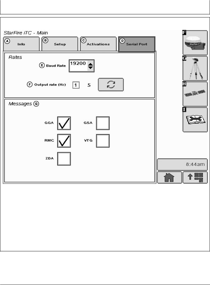
SERIAL PORT tab
PC9709 –UN–25SEP07
|
StarFire iTC - Main—Serial Port tab |
|
||
A—Info tab |
C—Activations tab |
E—Baud Rate |
G—Messages |
|
B—Setup tab |
D—Serial Port tab |
F—Output Rate |
|
|
Configure RS232 and NMEA message information. |
• |
Define output rate by toggling |
||
|
|
|
– 1Hz or 5Hz |
|
Rates: |
|
Messages: |
|
|
• Define Baud Rate by selecting list input |
• |
Allows for output of 5 different NMEA strings: |
||
– Baud Rates: 4800, 9600, 19200, 38400 |
|
– GGA, GSA, RMC, VTG, and ZDA |
||
OUO6050,0002247 –19–14NOV06–1/1
15-15 |
121907 |
PN=23

GS2 Display—StarFire iTC
NMEA Strings
NMEA String Data – Utilizing a third party GPS receiver or utilizing a StarFire iTC
National Marine Electronics Association (NMEA) has developed a specification that defines the interface between various pieces of electronic equipment.
One of the most important NMEA sentences include the GGA which provides the current Fix data, the RMC which provides the minimum GPS sentences information, and the GSA which provides the Satellite status data.
GGA - essential fix data which provide 3D location and accuracy data.
GGA STRING EXAMPLE:
$GPGGA,123519,4807.038,N,01131.000,E,
1,08,0.9,545.4,M,46.9,M,,*47
Where:
GGA |
Global Positioning System Fix Data |
|
|
|
|
123519 |
Fix taken at 12:35:19 UTC |
|
|
|
|
4807.038,N |
Latitude 48 deg 07.038’ N |
|
|
|
|
01131.000,E |
Longitude 11 deg 31.000’ E |
|
|
|
|
1 |
Fix quality: |
|
|
0 |
= invalid |
|
1 |
= GPS fix (SPS) |
|
2 |
= DGPS fix |
|
3 |
= PPS fix |
|
4 |
= Real Time Kinematic |
|
5 |
= Float RTK |
|
6 |
= estimated (dead reckoning) |
|
7 |
= Manual input mode |
|
8 |
= Simulation mode |
|
|
|
08 |
Number of satellites being tracked |
|
|
|
|
0.9 |
Horizontal dilution of position |
|
|
|
|
545.4,M |
Altitude, Meters, above mean sea level |
|
|
|
|
46.9,M |
Height of geoid (mean sea level) above WGS84 |
|
|
|
|
Continued on next page |
OUO6050,0000ED9 –19–07NOV07–1/4 |
15-16 |
121907 |
PN=24

GS2 Display—StarFire iTC
GSA - GPS DOP and active satellites. This sentence provides details on the nature of the satellite constellation fix. It includes the numbers of the satellites being used in the current solution and the DOP. DOP (dilution of precision) is an indication of the effect of satellite geometry on the accuracy of the fix. It is a unitless number where smaller is better. For 3D fixes using 4 satellites a 1.0 would be considered to be a perfect number, however for overdetermined solutions it is possible to see numbers below 1.0.
There are differences in the way the PRN’s are presented which can effect the ability of some programs to display this data. For example, in the example shown below there are 5 satellites in the solution and the null fields are scattered indicating that the almanac would show satellites in the null positions that are not being used as part of this solution. Other receivers might output all of the satellites used at the beginning of the sentence with the null field all stacked up at the end. This difference accounts for some satellite display programs not always being able to display the satellites being tracked. Some units may show all satellites that have ephemeris data without regard to their use as part of the solution but this is non-standard.
GSA String Example
$GPGSA,A,3,04,05,,09,12,,,24,,,,,2.5,1.3,2.1*39
Where:
GSA |
Satellite status |
|
|
|
|
A |
Auto selection of 2D or 3D fix (M = manual) |
|
|
|
|
3 |
3D fix - values include:: |
|
|
1 |
= no fix |
|
2 |
= 2D fix |
|
3 |
= 3D fix |
|
|
|
04,05 |
PRNs of satellites used for fix (space for 12) |
|
|
|
|
2.5 |
PDOP (dilution of precision) |
|
|
|
|
1.3 |
Horizontal dilution of precision (HDOP) |
|
|
|
|
2.1 |
Vertical dilution of precision (VDOP) |
|
|
|
|
*39 |
the checksum data, always begins with * |
|
|
|
|
Continued on next page |
OUO6050,0000ED9 –19–07NOV07–2/4 |
15-17 |
121907 |
PN=25

GS2 Display—StarFire iTC
RMC - NMEA has its own version of essential gps pvt (position, velocity, time) data. It is called RMC, The Recommended Minimum, which will look similar to:
RMC String Example
$GPRMC,123519,A,4807.038,N,01131.000,
E,022.4,084.4,230394,003.1,W*6A
Where:
RMC |
Recommended Minimum sentence C |
|
|
123519 |
Fix taken at 12:35:19 UTC |
|
|
A |
Status A=active or V=Void. |
|
|
4807.038,N |
Latitude 48 deg 07.038’ N |
|
|
01131.000,E |
Longitude 11 deg 31.000’ E |
|
|
022.4 |
Speed over the ground in knots |
|
|
084.4 |
Track angle in degrees True |
|
|
230394 |
Date - 23rd of March 1994 |
|
|
003.1,W |
Magnetic Variation |
|
|
*6A |
The checksum data, always begins with * |
|
|
VTG - Velocity made good. The gps receiver may use the
LC prefix instead of GP if it is emulating Loran output.
VTG String Example
$GPVTG,054.7,T,034.4,M,005.5,N,010.2,K*33
where:
VTG |
Track made good and ground speed |
|
|
054.7,T |
True track made good (degrees) |
|
|
034.4,M |
Magnetic track made good |
|
|
005.5,N |
Ground speed, knots |
|
|
010.2,K |
Ground speed, Kilometers per hour |
|
|
*33 |
Checksum |
|
|
ZDA - Data and Time
ZDA String Example
$GPZDA,hhmmss.ss,dd,mm,yyyy,xx,yy*CC
$GPZDA,201530.00,04,07,2002,00,00*6E
Continued on next page |
OUO6050,0000ED9 –19–07NOV07–3/4 |
15-18 |
121907 |
PN=26
GS2 Display—StarFire iTC
where:
hhmmss |
HrMinSec(UTC) |
|
|
dd,mm,yyy |
Day,Month,Year |
|
|
xx |
local zone hours -13..13 |
|
|
yy |
local zone minutes 0..59 |
|
|
*CC |
checksum |
|
|
|
|
OUO6050,0000ED9 |
–19–07NOV07–4/4 |
|
|
|
|
PC8663 |
–UN–05AUG05 |
|
|
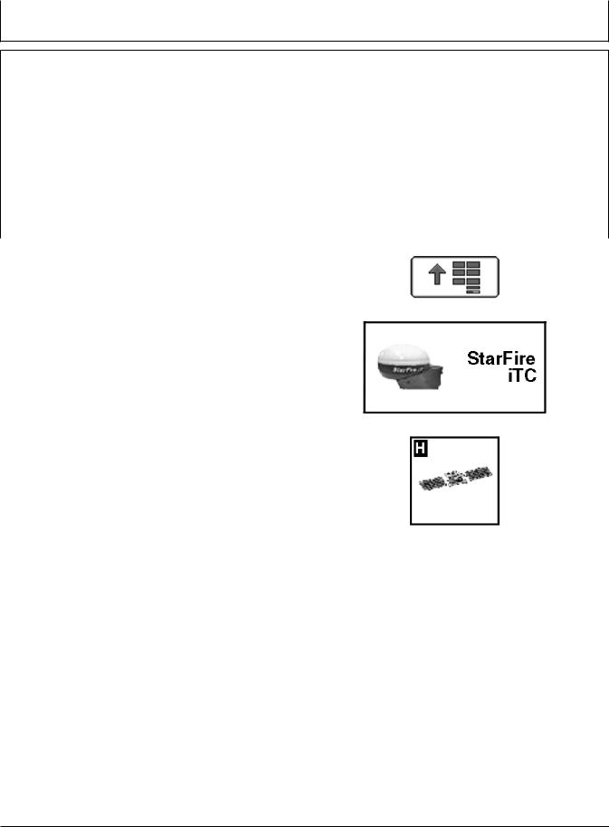
SATELLITE INFORMATION softkey |
|
|
|
Press: MENU button >> STARFIRE ITC button >> |
|
|
|
SATELLITE INFORMATION softkey. |
|
MENU button |
|
PC8659 |
–UN–05AUG05 |
|
|
The StarFire iTC - Satellite Information screen contains |
|
|
|
SKY PLOT and GRAPH tabs. |
|
|
|
|
|
STARFIRE ITC button |
|
PC8682 |
–UN–05AUG05 |
|
|
|
SATELLITE INFORMATION softkey |
|
|
Continued on next page |
OUO6050,0002248 |
–19–14NOV06–1/4 |
|
15-19 |
121907 |
PN=27

GS2 Display—StarFire iTC
|
|
|
–UN–10NOV06 |
|
|
|
PC9711 |
|
StarFire iTC - Satellites |
|
|
A—Sky Plot tab |
D—Satellites Above Elevation |
F—Corrections Age |
I—PDOP |
B—Graph tab |
Mask |
G—VDOP |
J—Satellites on Sky Plot |
C—Satellites in Solution |
E—Satellites Tracked |
H—HDOP |
K—Satellite Tracking |
SKY PLOT tab
Illustrates where satellites are in relation to vehicles receiver. This allows operator to look at satellite geometry.
Reading Satellite Sky Plot
•Sky Plot is fixed so that North is always at top.
•Satellites are displayed as their satellite ID number that correspond to Satellite Tracking Chart located right of Sky Plot
–Red – indicates satellite is in search mode
–Blue – indicates satellite is being tracked
–Green – indicates satellite is OK (being used for corrections)
•Sky Plot consists of 3 concentric rings depicting 0, 30, and 60 degrees of elevation with directional crossbar intersection representing 90 degrees of elevation.
•Grey radial lines extending from center of Sky Plot represent azimuth. They are spaced 30 degrees apart and represent 30 and 60 degrees.
•Directional crossbar representing North, South, East, and West also represent azimuth at 0, 90, 180, and 270 degrees.
•W1 and W2 (WAAS/EGNOS) satellites and inmarsat satellites are not shown in Sky Plot.
Continued on next page |
OUO6050,0002248 –19–14NOV06–2/4 |
15-20 |
121907 |
PN=28

GS2 Display—StarFire iTC
Satellite Tracking Chart |
Satellite Tracking Information |
||||
• |
SAT ID – (Satellite Identification Number) |
Satellite Tracking information is displayed at bottom of |
|||
• |
Identification number for GPS Satellite. |
SKY PLOT and GRAPH tabs. |
|
||
ELV – (Position Elevation) Elevation in degrees |
• |
|
|
||
• |
above horizon for GPS satellite position |
Satellites in Solution – number of satellites used to |
|||
AZM – (Position Azimuth) Azimuth in degrees from |
• |
compute position. |
|
||
• |
true North for GPS satellite |
Satellites Above Elevation Mask – total number of |
|||
L1 SNR – (L1 Signal to Noise Ratio) Signal strength |
|
GPS satellites available to receiver that are above 7 |
|||
• |
for L1 GPS signal (signal to noise ratio) |
• |
degree elevation mask. |
|
|
L2 SNR – (L2 Signal to Noise Ratio) Signal strength |
Satellites Tracked – total number of GPS satellites |
||||
• |
for L2 GPS signal (signal to noise ratio) |
• |
tracked by receiver. |
|
|
Status – (GPS Signal Status) Status of GPS signal |
Corrections Age (sec) – age of differential correction |
||||
|
– |
Search – searching for satellite signal |
• |
signal to GPS (normally less than 10 seconds) |
|
|
– |
Track – tracking satellite signal and using it for |
VDOP – Vertical Dilution of Precision |
||
|
|
positioning |
• |
HDOP – Horizontal Dilution of Precision |
|
|
– |
OK – tracking satellite signal and using it for |
• |
PDOP – Positional Dilution of Precision is an |
|
|
|
positioning |
|
indicator of GPS satellite geometry as viewed by |
|
|
– |
OK SF1 – Tracking satellite signal and using it for |
|
receiver. A lower PDOP indicates better satellite |
|
|
|
positioning with STARFIRE single frequency |
|
geometry for calculating both horizontal and vertical |
|
|
– |
OK SF2 – Tracking satellite signal and using it for |
|
position. |
|
|
|
positioning with STARFIRE dual frequency |
|
|
|
|
|
|
Continued on next page |
OUO6050,0002248 –19–14NOV06–3/4 |
|
15-21 |
121907 |
PN=29
GS2 Display—StarFire iTC
PC9551 –UN–06NOV06
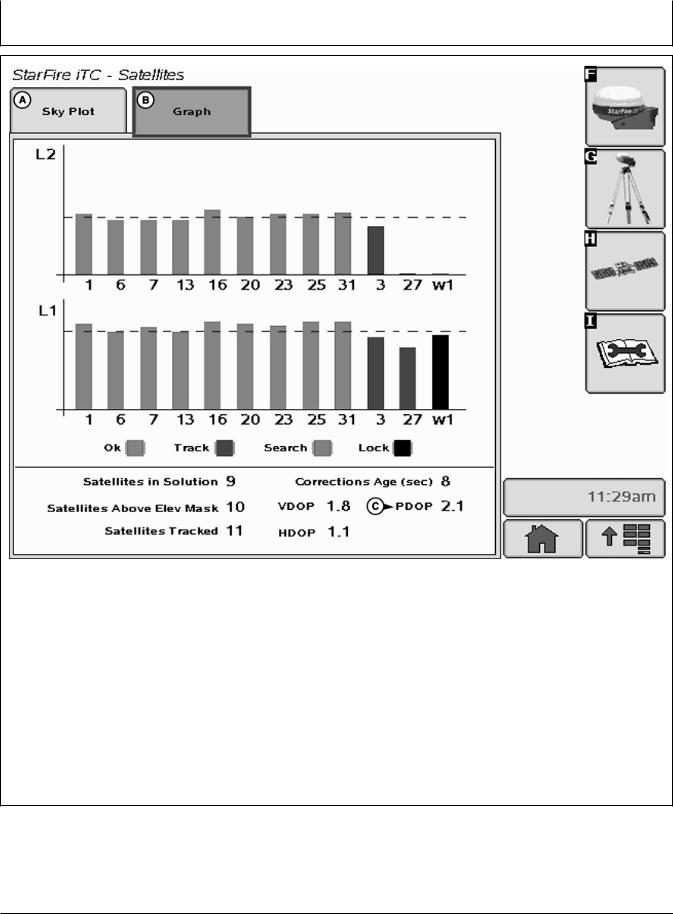
StarFire iTC - Satellites
A—SkyPlot |
B—Graph |
C—PDOP |
Graph
A graph illustrating L1 and L2 SNR values.
•Bars are colored to satellites current status.
•SNR values (colored bar) should be above dashed line that runs horizontally across bar graph.
NOTE: ONLY GREEN bars are used in calculation of PDOP, VDOP, AND HDOP. SNR’s are considered good if above dashed line.
OUO6050,0002248 –19–14NOV06–4/4
15-22 |
121907 |
PN=30
Loading...