


HR-BG5002, HR-BG5202, HR-BG6203
Barbecue Gas Grills
Operator’s Manual |
|

Introduction
THANK YOU for purchasing a John Deere product.
READ THIS MANUAL carefully to learn how to operate and service your machine correctly. Failure to do so could result in personal injury or equipment damage. This manual and safety signs on your machine may also be available in other languages. (See your John Deere dealer to order.)
THIS MANUAL SHOULD BE CONSIDERED a permanent part of your machine and should remain with the machine when you sell it.
MEASUREMENTS in this manual are given in both metric and customary U.S. unit equivalents. Use only correct replacement parts and fasteners. Metric and inch fasteners may require a specific metric or inch wrench.
WRITE SERIAL NUMBER in the Specification or
Identification Numbers section. Accurately record all the numbers to help in tracing the machine should it be stolen. Your dealer also needs these numbers when you order parts. File the identification numbers in a secure place off the machine.
WARRANTY is provided from your John Deere dealer for customers who operate and maintain their equipment as described in this manual. The warranty is explained on the warranty certificate shown in this manual.
This warranty provides you the assurance that your John Deere dealer will back products where defects appear within the warranty period. Should the equipment be abused, or modified to change its performance beyond the original factory specifications, the warranty will become void. Setting fuel delivery above specifications or otherwise overpowering the grill will result in such action.
Fuels used in gas or oil-fired appliances, and the products of combustion of such fuels, contain chemicals known to the State of California to cause cancer, birth defects or other reproductive harm.
“This warning is issued pursuant to California Health and Safety Code Sec. 25249.6”
|
Operator’s Manual |

|
Contents |
|
Page |
Safety .................................................................................. |
4 |
Controls ............................................................................. |
7 |
Installation .......................................................................... |
8 |
Preparation........................................................................... |
9 |
Operation............................................................................ |
14 |
Troubleshooting................................................................. |
21 |
Maintenance....................................................................... |
23 |
Storage................................................................................ |
25 |
Specifications..................................................................... |
26 |
Warranty.............................................................................. |
27 |
All information, illustrations and specifications in this manual are based on the latest information available at the time of publication. The right is reserved to make changes at any time without notice.
Operator’s Manual |
|
Safety
Recognize safety information
This is the safety alert symbol. When you see this symbol on your machine or in this manual, be alert to the potential for personal injury.
Follow recommended precautions and safe operating practices.
understand signal words
A signal word--DANGER, WARNING or CAUTION--is used with the safety-alert symbol. DANGER identifies the most serious hazards.
DANGER or WARNING safety signs are located near specific hazards. General precautions are listed on
CAUTION safety signs. CAUTION also calls attention to safety messages in this manual.
follow safety instructions
Carefully read all safety messages in this manual and on your grill safety signs. Keep safety signs in good condition. Replace missing or damaged safety signs. Be sure new equipment components and repair parts include the current safety signs. Replacement safety signs are available from your John Deere dealer.
Learn how to operate the grill and how to use controls properly. Do not let anyone operate without instruction. Incorrect operation of this unit can cause serious injury!
Keep your grill in proper working condition. Unauthorized modifications to the grill may impair the function and/or safety and affect grill life. Do not alter or modify this equipment in any manner!
Do not attempt to operate this unit until you have read and understood all safety precautions and instructions listed in this manual. If you do not understand any part of this manual and need assistance, contact your John Deere dealer.
Operator’s Manual
l.p-gas safety
Use the unit outdoors, away from open windows, vents, or doors.
This unit was designed for outdoor use only. NEVER operate this unit in an enclosed area.
If you smell gas:
1.Shut off gas to the appliance.
2.Extinguish any open flame.
3.Open lid.
4.If odor continues, immediately call your gas supplier or your fire department.
electrical hazards
If any accessory is used on this appliance that requires an external electrical power source, the accessory when installed must be electrically grounded in accordance with local codes. In the absence of local codes, the following standards apply:
(U.S.A.) ANSI/NFPA No. 70-Latest Edition (CANADA) CSA C22.1 Canadian Electrical Code
Do not cut or remove the grounding prong from the plug.
Keep the electrical supply cord and fuel supply hose away from any heated surface.
prepare for emergencies
Be prepared if a fire starts.
Keep a first aid kit and fire extinguisher handy.
Keep emergency numbers for doctors, ambulance service, hospital and fire department near your telephone.
IMPORTANT SAFETY INSTRUCTIONS
Your new gas grill is a safe, convenient appliance when assembled and used properly. However, as with all gas-fired products, certain safeguards must be observed. Failure to follow these safeguards may result in damage or injury. If you have questions concerning assembly or operation, consult your John Deere dealer, gas appliance serviceman, or your gas company:
1.DO NOT store or use gasoline, or other flammable vapors and liquids in the vicinity of this or any other appliance.
2.An LP cylinder not connected for use shall not be stored in the vicinity of this or any other appliance.
3.FOR OUTDOOR USE ONLY.
4.If stored indoors, detach and leave cylinder outdoors.
5.This appliance must not be operated unattended.
6.Special care must be taken to keep small children away from heated surfaces.
7.Follow the maintenance instructions specified in this manual.
!SAVE THESE INSTRUCTIONS!
Operator’s Manual

Location: Hose and Regulator
Location: Support Casting
Location: Control Panel
Operator’s Manual
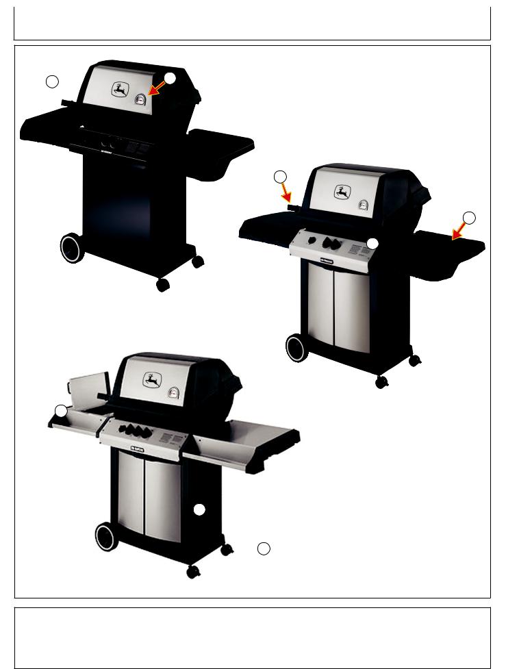
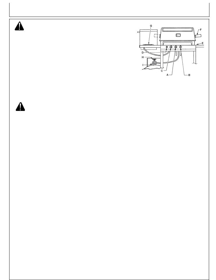
Controls
A  B
B
C
E
 D
D
HR-BG5002
HR-BG5202
F 
 G
G
 H
H
HR-BG6203
A-- |
Top Cover |
C-- |
Handle |
E |
--Side Shelf |
G |
--Front Doors |
B-- |
Thermostat |
D-- |
Controls |
F-- |
Side Burner |
H-- |
Locking Casters |
Operator’s Manual
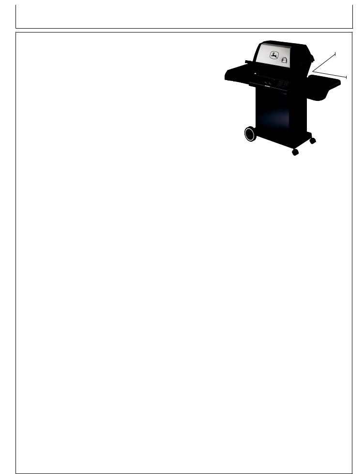
Installation
INSTALLATION
In the U.S.A., this appliance must be installed in accordance with the local code and the relevant national code: ANSI Z223.1-Latest
Edition National Fuel Gas Code
In Canada, this appliance must be installed in accordance with the local code and the relevant CGA standards: CAN/CGA-B149.2
LP Gas/Propane Installation Code and Latest Local Codes where Applicable
The appliance must be located away from combustible surfaces by at least 30”/76cm from each side, and 30”/76cm from the rear.
Do not operate this appliance under any overhead roof construction or foliage.
This appliance is for OUTDOOR USE ONLY, DO NOT operate in garage, shed, balcony or other such enclosed areas.
DO NOT restrict the flow of air to the appliance.
Keep the area surrounding the appliance free of combustible materials, gasoline, and all flammable liquids and vapors.
This appliance is not intended to be installed in, or on, recreational vehicles and/or boats.
30” / 76cm
30” / 76cm
Operator’s Manual
Preparation
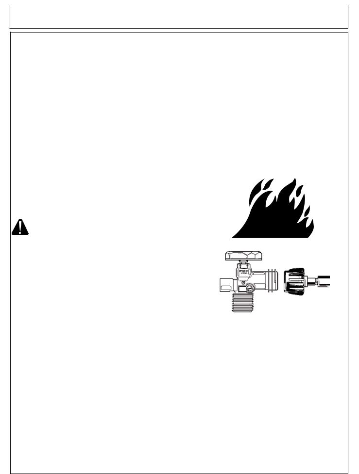
QCC®-1 QUICK CLOSING COUPLING
John Deere models are designed to be used with an LP-Gas Cylinder equipped with the new QCC®-1 Quick Closing Coupling system.
The QCC®-1 system incorporates new safety features required |
|
|
||
by the American National Standards Institute (ANSI) and the |
|
|
||
Canadian Standards Steering Committee. |
|
|
||
• |
Gas will not flow until a positive connection has been |
|
|
|
|
made. |
|
|
|
• |
A thermal element will shut off the flow of gas between |
|
|
|
|
240° and 300° F. |
|
|
|
• |
When activated, a Flow Limiting Device will limit the |
|
|
|
|
flow of gas to 10 cubic feet per hour. |
|
|
|
LP-GAS CYLINDER |
|
|
||
The LP-Gas Cylinder is not included with the Gas Grill. Be sure |
|
|
||
|
|
|||
to purchase one with the QCC® valve. This valve is recognized by |
|
|
||
the external threads on the inlet port of the valve. QCC® equipped |
|
|
||
cylinders are available from your local hardware stores or LP-Gas |
|
|
||
dealer. (Fig. 1) |
|
|
||
|
ARNING: Anyattempttoconnecttheregulator, |
|
|
|
|
by use of adapters or any other means, |
|
|
|
|
to any other valve could result in |
|
|
|
|
|
|
||
|
damage, fire or injury and may negate |
|
|
|
|
the important safety features designed |
|
|
|
|
into the QCC®-1 system. |
|
|
|
SPECIFICATIONS: |
|
|
|
|
1. |
All LP-Gas Cylinders used with this appliance must be |
|
|
|
|
constructed and marked with the specifications for LP- |
|
|
|
|
Gas Cylinders in accordance with the Canadian Transport |
|
|
|
|
Commission (CTC) for use in Canada, or the U.S. Department |
|
|
|
|
of Transport (DOT) for use in the U.S.A. |
|
|
|
|
|
Fig. 1 |
|
|
2. |
The LP-Gas Cylinder used for this appliance must not have a |
|
||
|
|
|||
|
capacity larger than 20 Ib. (9 kg). Approximately 18” (46cm) |
|
|
|
|
high 12” (31cm) diameter. |
|
|
|
3. |
All LP-Gas Cylinders used with this appliance should be |
|
|
|
|
inspected at every filling and re-qualified by a licensed service |
|
|
|
|
outlet at the expiry date (10 years), in accordance with the DOT |
|
|
|
|
(USA) and CTC (Canada) codes for LP-Gas Cylinders. |
|
|
|
4. |
All LP-Gas Cylinders used with this appliance must be provided |
|
|
|
|
with a shut-off valve terminating in a cylinder valve outlet No. |
|
|
|
|
510, specified in the Standard for Compressed Gas Cylinder |
|
|
|
|
Valve Outlet and Inlet Connection (USA)ANSI/CGA-V-1-1977 |
|
|
|
|
(Canada) CSA B96. |
|
|
|
The cylinder supply system must be arranged for vapor withdrawal. The cylinder must include a collar to protect the cylinder valve. The cylinder valve must include a safety relief device having direct communication with the vapor space of the cylinder.
Operator’s Manual
Preparation
LP-GAS CYLINDER
HANDLING:
1.Government regulations prohibit shipping full LP-Gas Cylinders. You must take your new cylinder to a LP-Gas dealer for filling.
2.A filled LP-Gas Cylinder is under very high pressure. Always handle carefully and transport in the upright position. Protect the valve from accidental damage.
3.Do not tip the LP-Gas Cylinder while connecting it to the regulator. Fasten the cylinder securely during transport, use and storage.
4.If the cylinder is tipped after it is connected to the regulator, shut off the gas, disconnect the regulator and have it checked before using again.
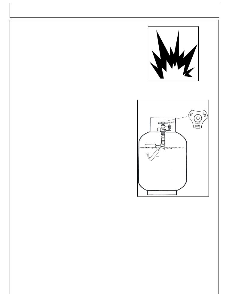
OVERFILL PREVENTION DEVICE:
Effective January 1, 1998, the standard for outdoor gas appliances,
ANSI Z21.58/CAN/CGA-1.6, requires that appliances are to be used with cylinders equipped with an Overfill Prevention Device
(OPD).
The OPD is designed to reduce the potential for the overfilling of propane cylinders, thus reducing the possibility of relief valve discharges of raw propane.The new OPD causes a slower purge/fill operation. Some consumers have been advised by filling stations that these cylinders are “defective”. This is not a defect. Some propane filling stations may not be aware of this new device and its effect on the purge/fill operation.
New OPDs coming onto the market have new technology that allows for much greater BTU outputs which will decrease the amount of time it takes to purge a cylinder.
To identify these cylinders, the new OPD hand-wheel has been standardized to the shape shown. (Fig. 2)
New OPD
Hand-Wheel
Filling stops |
OPD |
at 80% Full |
|
|
Float |
Fig. 2
10 |
Operator’s Manual |
Preparation
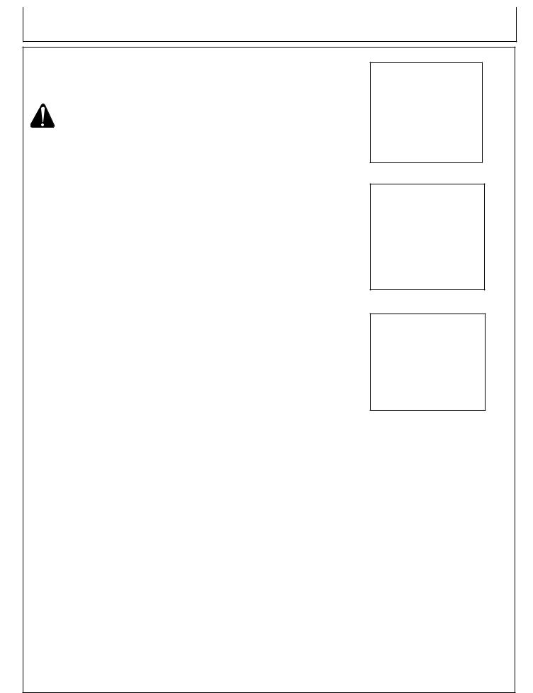
hose and regulator
John Deere models are equipped with a hose and regulator with a QCC®-1 Quick Closing Coupling.
The QCC® coupling contains a magnetic Flow Limiting Device which will limit the flow of gas should there be a leak between the regulator and the appliance valve. This device will activate if the cylinder valve is opened while the appliance valves are open. Be sure the appliance valves are off before the cylinder valve is opened to prevent accidental activation.
The QCC® coupling incorporates a heat sensitive hand wheel that will cause the back check module in the QCC® cylinder valve to close when exposed to temperatures between 240° and 300°F. Should this occur, do not attempt to reconnect the nut. Remove hose/regulator assembly and replace with a new one.
The pressure regulator is set at 11 inches WC (water column) and is for use with LP gas only. The hose and hose couplings comply with
CGA Standard CAN 1.83. No modifications or substitutions should be attempted.
Protect the hose from dripping grease and do not allow the hose to touch any hot surface, including the base casting of the grill.
Inspect seal in the QCC® cylinder valve when replacing LP gas cylinder or once per year whichever is more frequent. Replace seal if there is any indication of cracks, creases, or abrasion.
Inspect hose before each use of the grill. If the hose is cracked, cut, abraded or damaged in any way, the appliance must not be operated.
For repair or replacement of hose/regulator assembly, contact your dealer or approved service center.
CONNECTING REGULATOR TO LP-GAS CYLINDER:
1.Be sure cylinder valve and appliance valves are “off’.
2.Place full LP-Gas Cylinder on base mounting lip and secure top collar as per assembly instructions.
3.Center the nipple in the cylinder valve and hold in place.
Using other hand, turn the hand wheel clockwise until there is a positive stop. Do not use tools. Hand tighten only. When making the connection, hold the regulator in a straight line with the cylinder valve, so as not to cross thread the connection.
(Fig. 3)
4.Leak test connections. See “Leak Testing”.
5.Refer to lighting instructions. To avoid activating the Flow Limiting Device when lighting, open cylinder valve slowly with the appliance valves off. If the Flow Limiting Device is accidentally activated, turn off cylinder valve and appliance valves, wait 10 seconds to allow the device to reset, open cylinder valve slowly, then open the appliance valve.
Nipple with Flow
Limiting Device
Heat Sensitive
Hand-Wheel
|
Check |
Cylinder |
|
|
Shut-Off |
||
|
Valve |
||
Regulator |
Valve |
||
|
|||
|
|
||
|
|
|
|
|
Fig. 3 |
|
Operator’s Manual |
11 |
Preparation
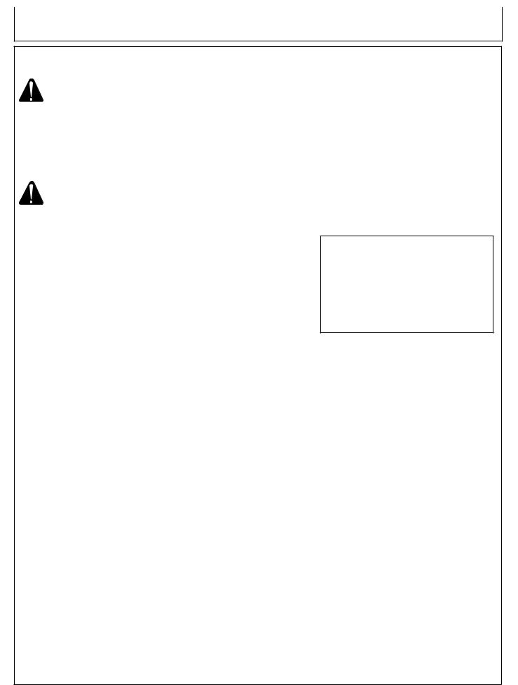
LEAK TESTING
All factory-made connections have been thoroughly tested for gas leaks.
However, shipping and handling may have loosened a gas fitting.
CAUTION: TEST ALL FITTINGS FOR LEAKS BEFORE USING YOUR GAS GRILL.
TEST THE CYLINDER VALVE FOR LEAKS EACH TIME THE CYLINDER IS FILLED.
TEST FOR LEAKS EVERY TIME YOU CONNECT A GAS FITTING.
DO NOT SMOKE!
NEVER TEST FOR LEAKS WITH A LIGHTED MATCH OR OPEN FLAME.
TEST FOR LEAKS OUTDOORS.
To test for leaks:
1.Extinguish any open flame or cigarettes in the area.
2.Be sure that cylinder valve and appliance valves are “off’.
3.Connect LP gas cylinder. See “Hose and Regulator”.
4.Prepare a soap solution of one part water, one part liquid detergent.
5.With a full gas cylinder, open cylinder slowly.
6.Brush the soap solution on each connection. (Fig. 4 & 5)
7.If your grill is equipped with a side burner or rear burner:
a.Place finger tip over the opening in the orifice at the end of hose.
b.Turn “SIDE”/“REAR” control to “HI”.
c.Brush soap solution on each connection between orifice and control valve. (Fig. 6)
d.Turn “SIDE”/“REAR” control to “OFF”.
8.A leak is identified by a flow of bubbles from the area of the leak.
9.If a leak is detected, close the gas cylinder “shut-off’ valve, tighten the connection and retest (Step 5).
10.If the leak persists, contact your grill dealer for assistance. Do not attempt to operate appliance if a leak is present.
Fig. 4
Fig. 5
Fig. 6
12 |
Operator’s Manual |
Preparation
VENTURI TUBES
CAUTION: KEEP VENTURI TUBES CLEAN. Blockages caused by spiders, insects and nests can cause a flashback fire. (Fig. 6)
Although the grill might still light, the backed up gas might also ignite and cause a fire around the venturi tubes at the control panel or side burner.
WARNING: If a flashback fire occurs, turn off gas at the source immediately.
Inspect and clean the venturi tubes (main burner, side burner, rear burner) if any of the following symptoms occur:
1.You smell gas.
2.Your grill does not reach temperature.
3.Your grill heats unevenly.
4.The burners make popping noises.
Inspecting & Cleaning Venturi Tubes:
1.Turn off gas at the source.
i.e. the gas cylinder or supply line for natural gas.
2.When grill is cool, remove burner fasteners from bottom, lift the burner from the grill housing.
3.Clean the venturi tubes with a pipe cleaner or venturi cleaning tool. (Fig. 7)
4.Lower the burner into position in the grill housing, making sure that the venturi tubes are correctly aligned and fitted on the orifices.
(Fig. 8)
5.Secure burner with burner fasteners.
Venturi Tube |
Spider Web |
|
Fig. 6 |
|
|
|
|
Fig. 7
Fig. 8
Operator’s Manual |
13 |
Operation
WARNING: Never connect your gas grill to an LP gas cylinder without the regulator provided, and NEVER TO AN UNREGULATED LP GAS SUPPLY. The gas regulator supplied with the appliance must be used.
Always leak test the LP gas cylinder to regulator connection when connecting the LP gas cylinder to the appliance. See “Leak Testing”.
Do not operate appliance if the smell of LP gas is present. Extinguish all flame and determine source of LP gas before proceeding. Do not ignite the appliance until The LP gas leak has been found and sealed.
CAUTION: Always shut off LP gas cylinder valve when the appliance is not in use.
LIGHTING GRILL
1.The appliance must be assembled as per the assembly instructions.
2.Check that your gas cylinder is full and properly connected to the regulator.
3.Check that there are no gas leaks in the gas supply system. See “Leak Testing”.
4.Check that the venturi tubes are properly located over the gas valve orifices.
5.Check that both Main Burner and Side Burner ignition wires are connected.
6.Read carefully all instructions contained on the information plate attached to the grill.
 WARNING: Open lid before lighting.
7.Set control knobs to “OFF” and turn on the gas supply.
8.Main Burner:
a.Push and turn right control knob to “Hi”.
b.Push the ignitor knob 3 or 4 times or match light. Burner should ignite within 5 seconds. (Ignition may perform better with right control knob or both control knobs set at medium.)
Note: To light burner with a match follow steps 1 thru 7 above.
c.Insertlightedmatchthroughlightingholelocatedatthebottomrightof the grill housing.
d.Push and turn right control knob to “Hi”.
e.Burner should ignite within 5 seconds.
f.After the right burner is lit, push and turn left control knob to “Hi”. Left burner will ignite automatically.
A. LEFT BURNER CONTROL |
F. HANDLE |
B. RIGHT BURNER CONTROL |
G. SIDE BURNER |
C. SIDE BURNER CONTROL |
H. CYLINDER VALVE |
D. IGNITOR |
I. REGULATOR |
E. MANUAL LIGHTING HOLE |
|
|
|
14 |
Operator’s Manual |
Operation
LIGHTING GRILL
Side Burner:
a.Push and turn control knob to “HI” Push the ignitor knob 3 or 4 times. Burner should ignite within 5 seconds.
Note: To light burner with a match follow steps 1 thru 7.
b.Apply lighted match to burner ports. Push in the control knob and turn to “HI”. Burner should ignite within 5 seconds.
 Caution - Check your grill after lighting.
9.All the ports on the burner should show a 2.5cm flame on “Hi” setting.
(Fig. 9)
If any of the following symptoms occur there is probably a blockage in the venturi tubes. Shut off gas at once and clean the venturi tubes. See “Venturi Tubes”.
a.You smell gas.
b.If a flashback fire occurs.
c.Your grill heats unevenly.
d.The burners make popping noises.
If burner does not ignite:
1.Push and turn control knob to “OFF”. Wait 5 minutes, then try again with right control knob or both control knobs set at medium.
2.If any burner will not light, consult “Trouble Shooting”. If problem cannot be resolved, do not attempt to operate the appliance; contact your dealer or approved service center.
SHUT DOWN
1.Turn off cylinder valve.
2.Turn control knobs to “OFF”.
COOKING GRIDS
The heavy mass of the cast iron girds absorbs heat and provides unsurpassed searing performance to lock in the natural juices of food on the grill. Cast iron grids are coated with a durable porcelain finish to assist in cleaning and help prevent rust. Some chipping may occur if mishandled. This will not affect the use of performance of the grids. If some rust appears, remove the rust with a scrub pad and coat the grid with cooking oil.
BEFORE FIRST USE: Wash the new cast iron grids with mild soap and water to remove any residue. Rinse thoroughly.
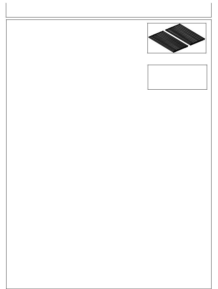
TO COOK: The grids may be used in the standard level or slope position (Fig. 10). When grilling lean meats, use the standard level position. The concave channels of the grids will cradle some of the food’s
juices to lubricate the grids to reduce sticking, and to baste the food while grilling. For foods that generate a lot of juices, use the slope position. Excess juices will run down the concave channels and drain away to the drip pan to help prevent excessive flare-ups.
TO CLEAN: With a grill brush, remove any remaining food.
Allow the grids to cool. Wash with mild soap and water, and wipe dry. Coat the grids with cooking oil when not in use.
Check Flame |
Burner |
Burner Ports
Fig. 9
SLOPE POSITION
Fig. 10
Operator’s Manual |
15 |

Operation
Burn-off
Before cooking on your gas grill for the first time, burn off the grill to rid it of any odors or foreign matter as follows:
Remove cooking grids and warming rack and wash in mild soap and water. Ignite the burner. Close the lid and operate the grill for 20 minutes with the control knobs set at “MEDIUM”. Turn the gas off at the source. Turn the control knobs to “Off”. Let the appliance cool down, replace the grids. You are now ready to use the appliance.
Preheating
It is necessary to preheat the grill with the lid closed for a short time before cooking certain foods. Food that requires a HIGH cooking temperature needs a preheat period of six to ten minutes; food that requires a lower cooking temperature needs only a period of two to five minutes. There is no need to preheat for casseroles or other food that requires slow cooking.
Lid Position
The position of the lid during cooking is a matter of personal preference, but the grill cooks fastest, uses less gas, and controls the temperature best with the lid closed. A closed lid also imparts a smokier flavor to meat cooked directly on the grid, and is essential for smoke, rotisserie and convection cooking.
COOKING TEMPERATURES
High Setting:
With the control knobs at HIGH, the surface temperature at the cooking grid is approximately 550° F (290° C) when the grill is warmed up. Use this setting only for fast warm-up, for searing steaks and chops, and for burning food residue from the cooking grids after
the cookout is over. Rarely, if ever, do you use the HIGH setting for extended cooking.
Medium Setting:
With the control knobs at MEDIUM, the temperature inside the grill is approximately 450° F (230°C) with the lid down. Use this setting for most grillingroasting, and baking, and for cooking hamburgers and vegetables.
Low Setting:
With the control knob at LOW, the temperature inside the grill is approximately 350° F (175° C). Use this setting for all smoke cooking, rotisserie cooking, and when cooking very lean food such as fish.
NOTE: These temperatures are approximate only and vary with the outside temperature and the amount of wind.
NOTE: When cooking by the convection or rotisserie method, use a meat thermometer for best results.
16 |
Operator’s Manual |
Operation
COOKING TECHNIQUES
PREPARATION:
1 . Prepare food in advance to avoid delay and timing problems. If using marinade or spices, they should be applied before placing meat on the cooking grid.
2.Organize the area around the grill to include forks, tongs, oven mitts, sauces and seasonings, to allow you to stay in the vicinity of the grill while cooking.
3.Trim excess fat from meat to minimize the “flare-ups” that are caused by dripping grease.
4.To avoid the problem of food sticking to the cooking grid, coat the grids with vegetable oil or non-stick spray before lighting the burners.
5.Pre-heat the grill to the desired temperature with the cover closed, before starting to cook.
6.Vegetables are best done in aluminum foil with enough moisture to create steam. Cooking time for vegetables will be similar to baking or steaming on the electric range.
7.Check the gas supply before starting the grill.
GRILL COOKING:
Grill cooking is the most popular form of barbecuing. The techniques are dictated by personal taste.
1 . Hold the salt when cooking meats on the grill. The meat will stay juicier if the salt is added after cooking.
2.Don’t baste meats until they are one-third to one-half cooked. Sauces with tomato, sugar, and oil burn easily and can produce unappetizing results if allowed to burn.
3.To prevent steaks from “drying out”, use tongs rather than a fork and start on “HIGH” to sear the meat and seal the juices in. Reduce the heat when the meat is well browned. Generally, thicker cuts of meat will stay moist better on a grill.
4.To test when the meat is done, make a small cut at the thickest section or near the bone to check color.
5.For best results, don’t let the flames reach the food. If “flare-ups” occur, remove the food. This will eliminate the “burned taste”, particularly for chicken and pork.
6.Grilling with the cover closed on low heat will enhance the “smoked” flavor.
7.After cooking, close the cover and turn burners to “HIGH” for approximately 10 minutes to burn off any residue on the grids.
8.For additional heat adjustment use two position cooking grid to raise and lower cooking surface.
Meat Thermometer Guide
Beef / Lamb |
Rare |
55°C |
130°F |
Beef / Lamb |
Medium |
66°C |
150°F |
Beef / Lamb |
Well Done |
71°C |
160°F |
Veal |
Well Done |
65°C |
150°F |
Pork |
Well Done |
77°C |
170°F |
Poultry |
Well Done |
77°C |
170°F |
Grill Cooking Guide
|
|
|
Cooking Time: |
||
Meat |
Size / Weight |
Temp. |
Rare - Well Done |
||
Hamburger |
Patties |
Low - Med |
12 |
- |
14 Minutes |
Steaks |
1” Thick |
Medium |
8 |
- |
12 Minutes |
Steaks |
1” - 2” Thick |
Medium |
16 |
- |
24 Minutes |
Lamb Chops |
2” Thick |
Low - Med |
15 |
- |
25 Minutes |
Pork Chops |
1” Thick |
Low - Med |
25 |
- |
30 Minutes |
Spare Ribs |
Whole |
Low |
40 |
- |
60 Minutes |
Chicken Wings |
Whole |
Low |
25 |
- |
35 Minutes |
Chicken Breast |
Whole |
Low |
30 |
- |
45 Minutes |
Fish Fillet |
1-1/2” Thick |
Low - Med |
15 |
- |
20 Minutes |
Lobster (Split) |
Whole / Tails |
Low |
15 |
- |
20 Minutes |
Operator’s Manual |
17 |
Operation
CONVECTION COOKING:
This method is ideal for roasting large cuts of meat with or without a rotisserie.
1.Set up the grill before lighting. Place drip pan beneath center of food. Put half to one inch of water in the drip pan. Fruit juice, wine or a marinade may also be added to enhance the flavor. Do not let the drip pan run dry.
2.For roasting without a rotisserie, place meat in a roasting rack directly on the grids.
3.In most cases convection cooking is best with the cover closed and the heat reduced.
4.Turn grill off and allow it to cool before removing drip pan.
AUTION: The fat drippings are highly flammableandmustbehandledcarefully to avoid injury.
Convection / Rotisserie Cooking Guide
Meat |
Size / Weight |
Temp. |
Rare - Well Done |
||
Beef Roast |
3-6 lbs. |
Low - Med |
2 |
- |
4 Hours |
Beef Roast |
6-10 lbs. |
Low - Med |
3 |
- |
5 Hours |
Pork Roast |
2-5 lbs. |
Low - Med |
2 |
- |
4 Hours |
Pork Roast |
6-10 lbs. |
Low - Med |
3 |
- |
5 Hours |
Turkey / Chicken |
2-5 lbs. |
Low - Med |
2 |
- |
4 Hours |
Turkey / Chicken |
5-10 lbs. |
Low - Med |
3 |
- |
5 Hours |
ROTISSERIE COOKING: |
|
|
Fig. 11 |
||
1. The rotisserie can accommodate up to 7 kg (15 Ib) of meat |
||
|
||
with the limiting factor of rotating clearance. |
|
|
For best results the meat should be centered on the center |
|
|
line of the spit to eliminate an out-of-balance condition. |
|
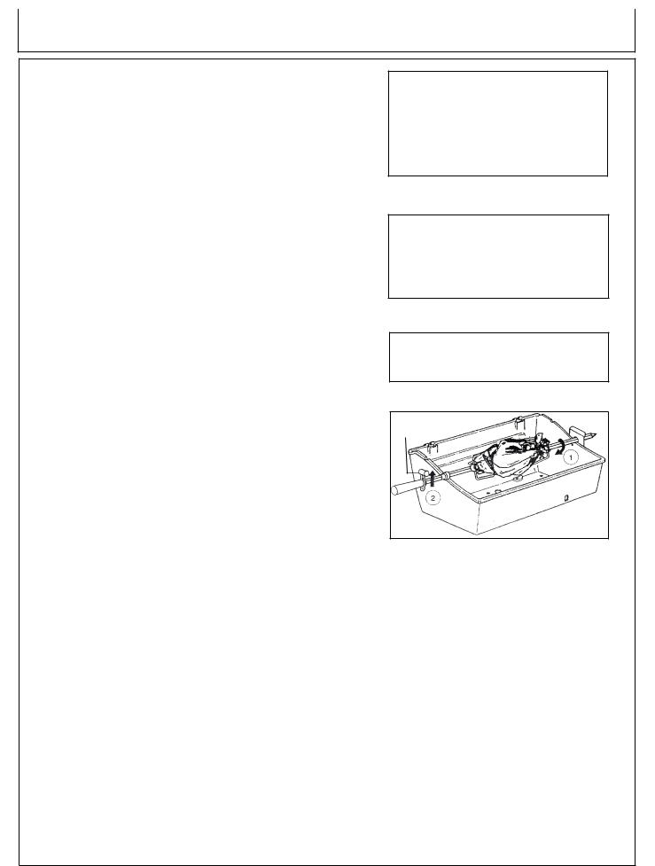
2.The rotisserie can be used with a cooking grid if space allows. Place the meat closest to the handle on the spit to make handling easier. (Fig. 11)
3.Fasten the meat securely on the spit prior to placing it on the grill. For poultry, tie the wings and legs in tightly to avoid contact with drip pan.
4.In most cases rotisserie cooking is best with the cover closed and the heat reduced.
5.Prior to placing the meat on the grill. baste the meat with vegetable oil. This will enhance the browning on the outside of the meat.
6.For most applications of rotisserie cooking, a drip pan is recommended to catch the drippings. Put half to one inch of water in the drip pan. Fruit juice, wine or a marinade may also be added to enhance the flavor. Do not let the drip pan run dry. For cooking without a drip pan, close attention must be paid to avoid the risk of grease fire.
7.Use oven mitts when handling the spit or working around the grill to avoid injury.
8.Turn grill off and allow it to cool before removing drip pan.
AUTION: The fat drippings are highly flammableandmustbehandledcarefully to avoid injury.
18 |
Operator’s Manual |
Operation
cooking with spit: Leg of Lamb (Fig. 12)
1.Have 3” of bone sawed from small end of leg.
2.Leave meat around bone intact to form a flap. Put a spit fork on rod.
3.Fold flap up and run rod through flap and leg.
4.Put second fork on rod and insert forks in each end of leg.
5.Test for balance. Tighten screws.
Poultry (Fig. 13)
1.With breast down; bring neck skin up over cavity.
Turn under edges of skin; skewer to back skin. Loop twine around skewer and tie.
Turn breast side up; tie or skewer wings to body.
2.Put a spit fork on rod. Insert rod in neck skin parallel to backbone; bring it out just above tail.
Put second fork on rod and insert forks in breast and tail. Test for balance. Tighten screws.
3.Tie tail to rod with twine. Cross legs; tie to tail.
Three Chickens on a Spit (Fig. 14)
1.Tie or skewer wings to body.
2.Put a spit fork on rod. Dovetail chickens on rod. Loop twine around tails and legs; tie to rod.
3.Put second fork on rod and insert forks in chicken. Tighten screws.
Spit Balance (Fig. 15)
1.Loosen the rod handle to allow the balance to turn freely. Set the rotisserie rod in the slots of the grill casting. Let the heaviest side of the meat rotate to the bottom.
2.Adjust the balance to the top of the rod, opposite the heaviest side of the meat. Tighten the rod handle. Periodically, check to see if the meat turns smoothly while cooking. Adjust the balancer as necessary.
Fig. 12
Fig. 13
Fig. 14
Spit Balance
Fig. 15
Operator’s Manual |
19 |
Operation
THERMOMETER:
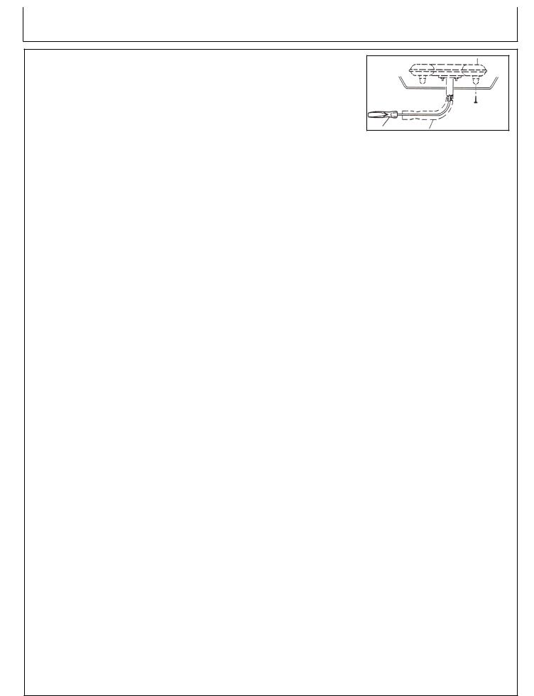
1.The accurate way to determine when a large piece of meat is done is to use a grill thermometer. Insert the thermometer at an angle so the sturdy pointed metal tip rests in the center of the thickest part of the meat. Be careful that it doesn’t touch the spit or the bone, and that the point is not resting in fat.
2.Leave the thermometer in place while the meat revolves. When the thermometer reaches the desired temperature the meat is done. Add your sauces during the last few minutes of cooking time, then take the meat off spit and let the meat stand about
15 minutes to firm up. Carve and serve.
For poultry: Insert the tip of the thermometer in the thickest part of the thigh close to the body. (Fig. 16)
For ham or roasts: Insert the tip of the thermometer in the center of the heaviest section of the meat. (Fig. 17)
Fig. 16
Fig. 17
20 |
Operator’s Manual |
Troubleshooting
Symptom |
Problem |
Solution |
Smell Gas. |
|
Shut-off LP-Gas Cylinder Valve |
|
|
at once. DO NOT use the |
|
|
appliance until leak is sealed. |
Leak detected at cylinder, regulator or Regulator fitting loose. other connections.
Gas leak in hose/regulator or control valves.
Flame flashback beneath control panel. Venturi blocked.
Burner will not light. |
Out of LP-Gas. |
|
Ignitor wire(s) not connected. |
|
Ignitor electrode misaligned on burner. |
|
Ignitor malfunction. |
|
Regulator is not fully connected to the |
|
cylinder valve. |
|
Burner valve left open while cylinder |
|
valve was opened causing excess |
|
flow device to activate. |
|
A leak in the system causing the |
|
excess flow device to activate. |
|
Venturi blocked. |
|
Venturi not aligned with valve orifice. |
|
Orifice blocked. |
Tighten fitting and “Leak Test”.
See authorized service center.
Remove burner, clean ventrui.
See “Venturi Tube”.
Refill LP-Gas Cylinder.
Connect both main burner and side burner electrode wires.
Realign electrodes.
Use “Manual Lighting” procedures.
Tighten the regulator hand-wheel.
Close burner and cylinder valves. Open cylinder valve slowly, then open burner valve to light.
Leak test connections to determine loose fitting. Tighten fitting. Leak test system.
Remove burner, clean venturi See “Venturi Tubes”.
Realign venturi to orifice. See
“Venturi Tubes”.
Remove burner, clean orifice with a pin or fine wire. Do not attempt to drill orifice.
|
Hose is twisted. |
Straighten hose. Keep away from |
|
|
bottom casting. |
Decreasing heat, “popping sound”. |
Out of LP-Gas. |
Refill LP-Gas Cylinder. |
|
Venturi blocked. |
Remove burner, clean venturi. |
|
|
See “Venturi Tubes”. |
Hot spots on cooking surface. |
Venturi blocked. |
Remove burner, clean venturi. |
|
|
See “Venturi Tubes” |
Operator’s Manual |
21 |

Troubleshooting
Symptom |
Problem |
Solution |
“Flare-ups” or grease fires. |
Excessive heat. |
Turn burner controls to a lower |
|
|
setting or raise cooking grid to up |
|
|
per position (2-position grids only). |
Humming noise from regulator. |
Cylinder valve turned on too quickly. |
Turn cylinder valve on slowly. |
Yellow Flame. |
Some yellow flame is normal. If it |
Remove burner, clean venturi. |
|
becomes excessive the venturi may |
See “Venturi Tubes”. |
|
be blocked. |
|
|
Burner ports blocked. |
Remove burner & clean with soft |
|
|
bristle brush. |
Inside of lid appears to be peeling. |
This is a build up of grease not |
Clean with stiff bristle brush or |
|
faulty paint. |
scraper. |
22 |
Operator’s Manual |
Maintenance
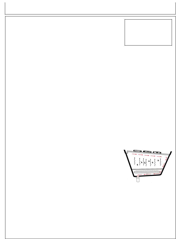
General Cleaning:
When the grill is cold, remove the grids. Cover three quarters of the Flav-R- Wave with aluminum foil, shiny side down. Ignite the burners; operate the grill on HIGH with the lid closed for 10 minutes or until smoking stops. Turn the gas cylinder valve to OFF, turn the control knobs to OFF. When the grill is cool, remove the foil, and residue from Flav-R-Wave with a vacuum. Remove Flav-R-Wave, then clean the interior of the bottom oven by scrapping the sides and vacuuming.
PERIODIC MAINTENANCE:
After you have finished, prepare for the next cookout by burning off any residue of food from the grid and Flav-R-Wave in the following manner:
Cooking Grids (Fig. 18)
Remove all food from the grids, turn the control knobs to “HIGH”, and operate the grill with the lid closed for 5 to 10 minutes or until smoking stops. Turn the gas cylinder valve to OFF, then the control knobs to OFF.
Use a long-handled wire brush to clean the grids. Remember that the grill is hot, so wear kitchen mitts or use a pot-holder to handle the brush.
You do not have to wash the grids and upper cooking rack after each cookout, but if you wish to do so, use a mild soap and water solution, then rinse them thoroughly. Never use a commercial oven cleaner.
Flav-R-Wave (Fig. 19)
If any residue begins to accumulate on the Flav-R-Wave, remove cooking grids and scrape excess residue with back of grill brush.
Fig. 18
Fig. 19
Operator’s Manual |
23 |
Maintenance
ANNUAL MAINTENANCE:
To ensure safe and efficient performance, the following components should be inspected and cleaned at least once per year or after any period of storage exceeding one month.
Burner
Remove burner and inspect for cracks and deterioration. (Fig. 20) Clean ven-
turi tubes using a pipe cleaner or venturi brush to eliminate any blockages Fig. 20 caused by spiders or insects. See “Venturi Tubes”.
While burner is removed, clean interior of bottom oven by scrapping the sides and vacuuming.
Hose
Inspect and replace if necessary. See “Hose and Regulator”.
Perm a-Mold Shelves
Wash with soap and water. To enhance luster, coat lightly with cooking oil.
Exterior Finish
If white oxidation spots appear, wash the outside of the housing with a mild soap and water solution. Rinse the surfaces thoroughly, then wipe them with a cloth dipped in cooking oil to restore the luster.
For repair of paint scratches and scuffs, use a good quality HIGH temperature (600°F) spray paint for touch-up.
Replacement Parts
If a problem is found with the regulator, hose, burner, or control valves, do not attempt repair. See your dealer, approved service center, or contact the factory for repairs or replacement parts. To ensure optimum performance, use only original John Deere replacement parts.
Leak Test
After reconnecting gas cylinder, be sure to check for leaks. See “Leak Testing”
24 |
Operator’s Manual |
 Loading...