


 Loading...
®
®
OWNER/OPERATOR MANUAL
®
TF6-42
9150-4003
March 2003
Starting Serial No. 0192001 thru 0192007
& 0160000052 thru Current
Form #20136 Original Issue 03/03
CORPORATE OFFICE |
GRADALL DIVISION |
JLG INDUSTRIES, INC. |
JLG INDUSTRIES, INC. |
1 JLG DRIVE |
406 Mill Avenue S.W. |
McConnellsburg, PA |
New Philadelphia, OH |
17233-9533 |
44663 |
USA |
USA |
Telephone: (717) 485-5161 |
Telephone: (330) 339-2211 |
Fax: (717) 485-6417 |
Fax: (330) 339-8458 |
TF6-42 MATERIAL HANDLER
“TRANSFORMER SERIES”
OWNER/OPERATOR MANUAL
COVERING OPERATION & PERIODIC MAINTENANCE

 m a t e r i a l h a n d l e r
IMPORTANT!
Read and understand this Manual, the Transformer Series Work Platform Owner/Operator Manual, the Gradall Material Handler Safety Manual, the ANSI A92.5 Responsibilities Manual, and the EMI Aerial Work Platform Safety Manual before starting, operating or performing maintenance procedures on this machine.
KEEP OPERATOR AND SAFETY MANUALS IN CAB
A |
® Company |
|
|
|
|
|
COVERS MATERIAL HANDLER TF6-42 |
® |
|
Form No. 20136 |
Part No. 9150-4003 |
|||
STARTING SERIAL NUMBER 0192001 THRU 0192007 |
||||
AND SERIAL NUMBER 0160000052 THRU CURRENT

1234567890123456789012345678901212345678901234567890123456789012123456
123456789012345678901234567890121234567890123456789012345678901212345123456789012345678901234567890121234567890123456789012345678901212345123456789012345678901234567890121234567890123456789012345678901212345123456789012345678901234567890121234567890123456789012345678901212345IMPORTANT SAFETY NOTICE 6666 123456789012345678901234567890121234567890123456789012345678901212345 6 123456789012345678901234567890121234567890123456789012345678901212345 6
1234567890123456789012345678901212345678901234567890123456789012123456
Safe operation depends on reliable equipment and proper operating procedures. Performing the checks and services described in this Manual will help keep your JLG/GRADALL Material Handler in reliable condition. Following recommended operating procedures can help you avoid accidents. Because some procedures may be new to even the experienced operator, we require that this Manual be read, understood and complied with by all who operate this machine.
Strict attention to and compliance with instructions provided in this Manual, the Transformer Series Work Platform Owner/Operator Manual, the GRADALL Material Handler Safety Manual, the ANSI A92.5 Responsibilities Manual, the EMI Aerial Work Platform Safety Manual, as well as instructional decals and plates affixed to the machine and attachments will help prevent injuries to personnel and damage to the equipment. The information provided herein is not intended to cover all situations; it is impossible to anticipate and evaluate all possible applications and methods of operation for this equipment.
This Manual covers recommended operating procedures and basic maintenance checks and services for the Material Handler. Detailed maintenance information is available in the appropriate Service Manual.
Any procedure not specifically recommended by JLG/GRADALL must be thoroughly evaluated from the standpoint of safety before it is placed in practice. If you are not sure, contact your JLG/GRADALL Material Handler Distributor before operating.
Use only JLG/GRADALL authorized parts. The use of counterfeit parts may cause premature failure which could lead to injuries and/or machine damage.
1234567890123456789012345678901212345678901234567890123456789012123456789012345678901234
123456789012345678901234567890121234567890123456789012345678901212345678901234567890123
123456789012345678901234567890121234567890123456789012345678901212345678901234567890123
123456789012345678901234567890121234567890123456789012345678901212345678901234567890123
123456789012345678901234567890121234567890123456789012345678901212345678901234567890123Do not modify this machine without written
123456789012345678901234567890121234567890123456789012345678901212345678901234567890123
123456789012345678901234567890121234567890123456789012345678901212345678901234567890123
123456789012345678901234567890121234567890123456789012345678901212345678901234567890123
123456789012345678901234567890121234567890123456789012345678901212345678901234567890123
123456789012345678901234567890121234567890123456789012345678901212345678901234567890123permission from JLG/GRADALL. Use only
123456789012345678901234567890121234567890123456789012345678901212345678901234567890123
123456789012345678901234567890121234567890123456789012345678901212345678901234567890123
123456789012345678901234567890121234567890123456789012345678901212345678901234567890123
123456789012345678901234567890121234567890123456789012345678901212345678901234567890123
123456789012345678901234567890121234567890123456789012345678901212345678901234567890123genuine JLG/GRADALL replacement parts.
123456789012345678901234567890121234567890123456789012345678901212345678901234567890123
123456789012345678901234567890121234567890123456789012345678901212345678901234567890123
1234567890123456789012345678901212345678901234567890123456789012123456789012345678901234
4
4
4
4
4
4
4
4
4
4
4
4
4
4
4
4
OTHER NOTICES
JLG/GRADALL retains all proprietary rights to the information contained in this Manual.
JLG/GRADALL reserves the right to change specifications without notice.
GRADALL is a registered trademark for Hydraulic Excavators, Hydraulic Material Handlers and Attachments manufactured by The JLG/Gradall Company.

REVISIONS
This page is provided so you may determine that this Manual is complete and current with respect to JLG/ Gradall Engineering Specifications.
Page Date Revision
Form No. 20136 3/03 • TF6-42 Owner/Operator Manual

TABLE OF CONTENTS
MATERIAL HANDLER |
|
IMPORTANT SAFETY NOTICE ..................................................... |
inside front cover |
TABLE OF CONTENTS |
|
INTRODUCTION |
|
SAFETY HIGHLIGHTS ............................................................... |
1.0 |
DECALS ................................................................................. |
2.0 |
OPERATORS CAB ..................................................................... |
3.0 |
CHECKS & SERVICES BEFORE STARTING ENGINE ....................... |
4.0 |
WARM-UP & OPERATIONAL CHECKS........................................... |
5.0 |
ENGINE OPERATION ................................................................ |
6.0 |
BRAKE SYSTEM ....................................................................... |
7.0 |
PARKING THE HANDLER ........................................................... |
8.0 |
STEERING SYSTEM .................................................................. |
9.0 |
DRIVE TRAIN .......................................................................... |
10.0 |
LEVELING THE HANDLER ......................................................... |
11.0 |
OPERATING PROCEDURE & TECHNIQUES .................................. |
12.0 |
UNDERSTANDING RATED CAPACITY CHARTS ............................... |
13.0 |
“TRANSFORMER” WORK PLATFORM INSTALLATION ...................... |
14.0 |
ATTACHMENT INSTALLATION ..................................................... |
15.0 |
OBTAINING HYDRAULIC OIL SAMPLE FOR ANALYSIS .................... |
16.0 |
LOADING & SECURING FOR TRANSPORT .................................... |
17.0 |
MOVING HANDLER IN EMERGENCY ............................................ |
18.0 |
MAINTENANCE SECTION .......................................................... |
19.0 |
RECOMMENDED LUBRICANTS & CAPACITIES .............................. |
20.0 |
BOOM MAINTENANCE .............................................................. |
21.0 |
INSPECTION AND MAINTENANCE LOG ....................................... |
22.0 |
TRANSFORMER SERIES WORK PLATFORM |
|
IMPORTANT SAFETY NOTICE ..................................................... |
inside front cover |
TABLE OF CONTENTS |
|
INTRODUCTION |
|
SAFETY ................................................................................. |
P1.0 |
DECAL LOCATIONS .................................................................. |
P2.0 |
DECALS ................................................................................. |
P3.0 |
NOMENCLATURE ..................................................................... |
P4.0 |
WORK PLATFORM INSTALLATION............................................... |
P5.0 |
CHECKS BEFORE USING .......................................................... |
P6.0 |
WARM-UP & OPERATIONAL CHECKS .......................................... |
P6.1 |
DAILY “WALK-AROUND INSPECTION” ......................................... |
P6.2 |
DAILY REAR AXLE LOCK-OUT TEST PROCEDURE ......................... |
P7.0 |
PLATFORM CONTROLS & INDICATORS ....................................... |
P8.0 |
PLATFORM OPERATION ............................................................ |
P9.0 |
EMERGENCY PROCEDURES ....................................................... |
P10.0 |
|
INTRODUCTION |
|||||||||
General |
|
|
|
|
|
|
|
|
|
|
This Manual provides important information regarding safe operating and |
NOTE! |
|
|
|
|
|
|
|
|
|
maintenance requirements for JLG/GRADALL Material Handlers. Refer to front |
|
|
|
|
|
|
|
|
|
|
cover for specific model and serial number range. |
“Material handler” and handler |
|
||||||||
|
|
|||||||||
If you have any questions regarding the material handler, contact your JLG/ |
are used interchangeably |
|
||||||||
throughout this Manual. |
|
|||||||||
GRADALL Distributor. |
NOTE! |
|
|
|
|
|
|
|
|
|
Operator Qualifications |
|
|
|
|
|
|
|
|
|
|
Though no offense or |
|
|
||||||||
Operators of the material handler must be in good physical and mental |
|
|
||||||||
discrimination is intended, only |
|
|||||||||
condition, have normal reflexes and reaction time, good vision and depth |
|
|||||||||
the masculine pronouns will be |
|
|||||||||
perception and normal hearing. He must not be using medication which could |
used throughout the remainder |
|
||||||||
impair abilities nor be under the influence of alcohol or any other intoxicant |
of this Manual. |
|
|
|
|
|
|
|||
during the work shift. |
NOTE! |
|
|
|
|
|
|
|
|
|
The operator should possess a valid, applicable driver’s license and must |
|
|
|
|
|
|
|
|
|
|
In the U.S.A., the operator |
|
|||||||||
have completed a training course for this type of equipment. |
must have completed a training |
|||||||||
|
course meeting the OSHA |
|
||||||||
In addition, the operator must read/view, understand and comply with |
Powered Industrial Truck |
|
||||||||
instructions contained in the following material furnished with the material |
Operator Training |
|
|
|
|
|||||
Requirements (CFR 1910.178) |
|
|||||||||
handler: |
|
|||||||||
|
|
|
|
|
|
|
|
|
|
|
• This Owner/Operator Manual |
|
FRONT |
|
|
|
|||||
• The Transformer Series Work Platform Owner/Operator Manual |
|
|
|
|
||||||
|
|
|
|
|
|
|
|
|
|
|
• ANSI Responsibilities Manual |
|
|
|
|
|
|
|
|
|
|
• EMI Aerial Work Platform Safety Manual |
|
|
|
|
|
|
|
|
|
|
• GRADALL Material Handler Safety Manual |
|
|
|
|
|
|
|
|
|
|
• All instructional decals and plates |
|
|
|
|
|
|
|
|
|
|
• Any optional equipment instructions furnished |
|
|
|
|
|
|
|
|
|
|
The operator must also read, understand and comply with all applicable |
LEFT |
|
|
|
|
|
|
|
RIGHT |
|
Employer, Industry and Governmental rules, standards and regulations. |
|
|
|
|
|
|
|
|
||
|
|
|
|
|
|
|
|
|
|
|
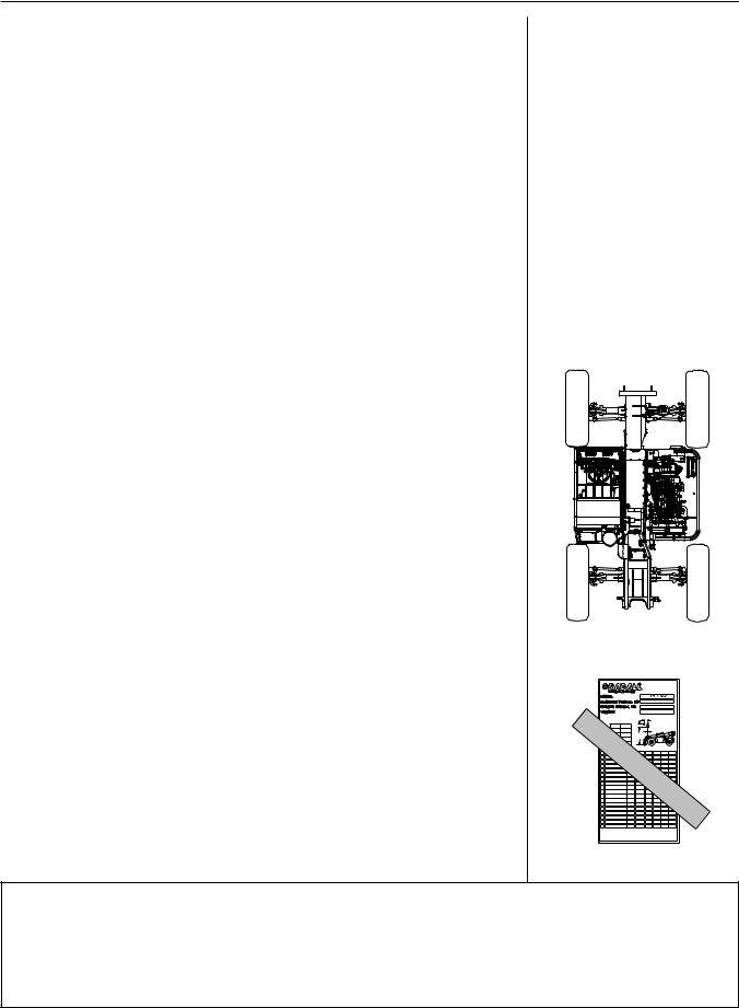
Orientation |
|
|
|
|
|
|
|
|
|
|
When used to describe the location of components in the material handler, |
|
|
|
|
|
|
|
|
|
|
the directions “front’”, “rear”, “right” and “left” relate to the orientation of a |
|
|
|
|
|
|
|
|
|
|
person sitting in the operator’s seat. (See figure I-1) |
|
|
|
|
|
|
|
|
|
|
Related Manuals & Decals |
|
|
|
|
|
|
|
|
|
|
Separate publications are furnished with the material handler to provide |
|
|
|
REAR |
|
|
|
|||
information concerning safety, replacement parts, maintenance procedures, |
|
|
|
|
|
|
||||
Figure I-1 |
|
|||||||||
theory of operation and vendor components. Replacement manuals, decals |
|
|||||||||
and instruction plates can be ordered from your JLG/GRADALL Distributor. |
|
|
|
|
|
|
|
|
|
|
Models Covered |
X1000 |
6.6 |
|
1.0 |
B |
19430 LBS |
|
|
||
This Manual covers basic information for JLG/Gradall Material Handlers. Detailed |
|
|
|
|
|
|
||||
|
AS RELEASED FROM FACTORY THIS TRUCK MEETS THE DESIGN SPECIFICATIONS |
|
|
|
||||||
|
ESTABLISHED IN AMERICAN NATIONAL STANDARDS FOR POWERED INDUSTRIAL |
|
|
|
||||||
|
TRUCKS PART III ASME B56.6b-1998. |
|
C |
|
|
|
|
|||
|
|
CAPACITY WITH STANDARD |
|
|
|
|
|
|||
|
|
48" & 72" CARRIAGE. |
|
|
|
|
|
|
||
information for each particular machine is in the maintenance section in the |
CAP# |
|
|
|
|
|
|
|
|
|
D |
2.0' |
|
26.9' |
|
|
|
|
|
|
|
|
A |
42' |
|
4.6' |
|
|
D |
|
|
|
|
B |
24" |
|
24" |
A |
|
|
|
|
|
back of this manual. Be certain to refer to proper information for your unit |
C |
24" |
|
24" |
|
|
|
|
|
|
48" SLOPE PILER |
CAP# |
|
A |
B |
C |
D |
|
|||
|
SHIPPED |
TT CH |
ENT |
|
|
|||||
|
WIT |
1000 |
|
|
||||||
|
48" C RRI GE |
|
6.6 |
20,180 |
42' |
24" |
24" |
2.0' |
|
|
|
P/N 9140-5073 |
* |
|
|||||||
|
72" CARRIAGE |
|
6.6 |
20,290 |
42' |
24" |
24" |
2.0' |
|
|
|
P/N 9140-5074 |
* |
|
|||||||
and the optional equipment furnished on your machine. |
P/N 9140-5101 |
* |
6.6 |
20,460 |
42' |
24" |
24" |
2.7' |
|
|
SAMPLE |
|
|
|
|
|
|||||
|
72" SLOPE PILER |
6.6 |
20,650 |
42' |
24" |
24" |
2.7' |
|
||
|
P/N 9140-5079 |
* |
|
|||||||
Serial Number Location (See figure I-2) |
|
|
|
|
|
ONLY |
|
|||
|
|
|
|
|
|
|
|
|
|
|
Specify Model Number and Serial Number when ordering parts and when |
|
|
|
|
|
|
|
|
|
|
discussing specific applications and procedures with your Distributor. The |
|
|
|
|
|
|
|
|
9147-3131 (B) |
|
model/serial number plate is located inside the operator’s cab, right wall. |
Figure I-2 |
|
||||||||
|
|
|||||||||
12345678901234567890123456789012123456789012345678901234567890121234567890123456789012345678901212345678901234567890123456789012 |
|
|
12345678901234567890123 |
4 |
||||||
12345678901234567890123456789012123456789012345678901234567890121234567890123456789012345678901212345678901234567890123456789012123456789012345678901234567890121234567890123456789012345678901212345678901234567890123456789012123456789012345678901234567890121234567890123456789012345678901212345678901234567890123456789012123456789012345678901234567890121234567890123456789012345678901212345678901234567890123456789012123456789012345678901234567890121234567890123456789012345678901212345678901234567890123456789012Important Notice ! |
|
|
12345678901234567890123123456789012345678901231234567890123456789012312345678901234567890123 4444 |
|||||||
12345678901234567890123456789012123456789012345678901234567890121234567890123456789012345678901212345678901234567890123456789012 |
|
|
12345678901234567890123 |
4 |
||||||
12345678901234567890123456789012123456789012345678901234567890121234567890123456789012345678901212345678901234567890123456789012This machine has been equipped with a serial number specific Transformer12345678901234567890123Series |
4 |
|||||||||
12345678901234567890123456789012123456789012345678901234567890121234567890123456789012345678901212345678901234567890123456789012 |
|
|
12345678901234567890123 |
4 |
||||||
12345678901234567890123456789012123456789012345678901234567890121234567890123456789012345678901212345678901234567890123456789012 |
|
|
12345678901234567890123 |
4 |
||||||
12345678901234567890123456789012123456789012345678901234567890121234567890123456789012345678901212345678901234567890123456789012 |
|
|
12345678901234567890123 |
4 |
||||||
12345678901234567890123456789012123456789012345678901234567890121234567890123456789012345678901212345678901234567890123456789012Personnel Work Platform. Do not exchange transformer platforms12345678901234567890123between |
4 |
|||||||||
12345678901234567890123456789012123456789012345678901234567890121234567890123456789012345678901212345678901234567890123456789012 |
|
|
12345678901234567890123 |
4 |
||||||
12345678901234567890123456789012123456789012345678901234567890121234567890123456789012345678901212345678901234567890123456789012 |
|
|
12345678901234567890123 |
4 |
||||||
machines. Doing so will require calibration changes to the controller that must be |
|
|||||||||
12345678901234567890123456789012123456789012345678901234567890121234567890123456789012345678901212345678901234567890123456789012 |
|
|
12345678901234567890123 |
4 |
||||||
12345678901234567890123456789012123456789012345678901234567890121234567890123456789012345678901212345678901234567890123456789012 |
|
|
12345678901234567890123 |
4 |
||||||
12345678901234567890123456789012123456789012345678901234567890121234567890123456789012345678901212345678901234567890123456789012 |
|
|
12345678901234567890123 |
4 |
||||||
12345678901234567890123456789012123456789012345678901234567890121234567890123456789012345678901212345678901234567890123456789012performed by a qualified service technician. This platform assembly12345678901234567890123is designed |
4 |
|||||||||
12345678901234567890123456789012123456789012345678901234567890121234567890123456789012345678901212345678901234567890123456789012 |
|
|
12345678901234567890123 |
4 |
||||||
12345678901234567890123456789012123456789012345678901234567890121234567890123456789012345678901212345678901234567890123456789012 |
|
|
12345678901234567890123 |
4 |
||||||
12345678901234567890123456789012123456789012345678901234567890121234567890123456789012345678901212345678901234567890123456789012 |
|
|
12345678901234567890123 |
4 |
||||||
soley for use with the Transformer Model Machines only. |
|
|
|
|
|
|
|
|
|
|
12345678901234567890123456789012123456789012345678901234567890121234567890123456789012345678901212345678901234567890123456789012 |
|
|
12345678901234567890123 |
4 |
||||||
12345678901234567890123456789012123456789012345678901234567890121234567890123456789012345678901212345678901234567890123456789012 |
|
|
12345678901234567890123 |
4 |
||||||
12345678901234567890123456789012123456789012345678901234567890121234567890123456789012345678901212345678901234567890123456789012 |
|
|
12345678901234567890123 |
4 |
||||||
12345678901234567890123456789012123456789012345678901234567890121234567890123456789012345678901212345678901234567890123456789012 |
|
|
12345678901234567890123 |
4 |
||||||
12345678901234567890123456789012123456789012345678901234567890121234567890123456789012345678901212345678901234567890123456789012 |
|
|
12345678901234567890123 |
4 |
||||||
234567890123456789012345678901212345678901234567890123456789012123456789012345678901234567890121234567890123456789012345678901 |
|
2123456789012345678901234 |
|
|||||||
Form No. 20136 3/03 • TF6-42 Owner/Operator Manual |
|
|
|
|
|
|
|
|
|
|

SAFETY HIGHLIGHTS
Read and understand all manuals and instructional material listed on cover, inside front cover and introduction page of this Manual before starting, operating or performing maintenance procedures on this equipment.
Regardless of previous experience operating similar equipment, the operator must be given sufficient opportunity to practice with the handler in a safe, open area (not hazardous to people or property) to gain operating skills and the proper “feel” for controls and operating clearances required for safe, efficient operation.
JLG/GRADALL Material Handlers are equipped with a right-side rearview mirror. This mirror is intended as an operator’s aid and does not replace the requirement for line-of-sight. Certain job site and machine conditions may require use of a signal person to help the operator when picking, placing or transporting a load. Never operate the handler until you know pick-up point, line of travel and landing point are clear. Always be aware that objects in mirror are closer than they appear.
Safety Precautions
Make sure all DANGER, WARNING, CAUTION and INSTRUCTIONAL DECALS are in place and can be read. Clean or replace decals as required.
Ensure handler is on a firm, level surface before lifting or placing load. Have surface leveled if necessary. Unit can tip over if load is raised with handler on a soft or uneven surface.
Be aware that when rotating the platform within indicated area on capacity charts, it can swing into tires. Be sure to allow clearance to avoid damage to tires.
When traveling at high rates of speed, use two wheel front steer mode and slow the machine prior to turning.
Do not change steer mode while the machine is traveling. Change the steer mode only when machine is stopped.
Always look in the direction of travel. Reduce speed and be especially careful when traveling in reverse and/or turning. Bring the machine to a complete stop before changing the direction of travel.
Travel in reverse only at slow rates of speed.
When turning, the forks on the four wheel steer machine sweep through an arc beyond the turn radius of the tires. Maintain adequate clearance between the forks/load and other objects.
If load or conditions obstruct view, use a signal person when lifting, carrying or placing a load.
Loose clothing can get caught in moving machinery and can also cause accidental actuation of controls. Dress properly for the job.
Be alert to any unusual response to controls. If unusual response is noticed, position handler in a safe area, lower forks to ground, apply parking brake, stop engine and remove key from ignition switch. Tag steering wheel to forbid operation and notify maintenance personnel.
1.0
WATCH FOR THESE SYMBOLS ; THEY CALL YOUR ATTENTION TO SAFETY NOTICES.
! DANGER
This symbol indicates an extreme hazard which will result in high probability of death or serious injury if proper precautions are not taken.
! WARNING
This symbol indicates a hazard which could result in death or serious injury if proper precautions are not taken.
! CAUTION
This symbol indicates a hazard which may result in injury or damage to equipment or property if proper precautions are not taken.
! WARNING
Operator must be seated with seat belt fastened, transmission control lever in “Neutral” position, parking brake applied and all hydraulic controls in “Neutral” before starting engine.

SAFETY HIGHLIGHTS
Keep hands, gloves, shoes, control knobs and pedals clean. Slippery controls can cause accidents. Keep a firm grip on the steering wheel when traveling.
Load capacities are based on load center being within .6m (24 inches) from front vertical face of forks.
Release trapped pressure before disconnecting, opening or removing any hydraulic component.
Keep all windows and mirror(s) clean. Adjust mirror(s) as required for maximum visibility, before and during operation.
Do not increase engine speed with the transmission in forward or reverse and the service brake pedal depressed in an attempt to get quicker hydraulic performance. This could cause unexpected machine movement.
After bringing the material handler to a stop using the service brake, place the directional control lever in neutral, and set the park brake prior to lifting a load.
Allow the handler to slow down, or use the service brakes prior to down-shifting.
Do not downshift more than one gear at a time.
When traveling on downhill slopes, downshift to a lower gear and use the service brake as necessary to maintain a slow speed. Do not shift into neutral and coast downhill.
Never permit diesel engine to run out of fuel. Doing so can cause severe engine damage.
DO NOT burn or drill holes in forks. Modifying any part of machine or attachment affects it’s capacity and/or stability of machine.
Keep head, arms, hands, legs and all other body parts inside the operator’s cab at all times.
DO NOT approach power lines, overhead or underground cables or other power sources with any part of your material handler or load unless all local, state/provincial and federal regulations have been met and the appropriate utility company’s hotline has been contacted to de-energize the lines.
Whenever leaving the cab, perform standard shut-down procedure:
Standard Shut-Down Procedure
Position the handler in a safe location, lower forks/attachment to ground, apply park brake, move all controls to “Neutral”, allow engine to run at low idle for 3 to 5 minutes. Rotate control station selector switch to “off”, remove key and place emergency stop button in run mode. Chock wheels.
! WARNING
Contact The JLG/Gradall Company prior to welding on machine.
! WARNING
Do not operate the “transformer series” platform without proper installation, including electrical and hydraulic connections in place.
! WARNING
Do not allow personnel to tamper with or operate the machine from the cab with personnel in the platform equipped with controls, except in an emergency.
Do not allow others to occupy cab while platform controls are in use.
|
1.1 |
Form No. 20136 3/03 • TF6-42 Owner/Operator Manual |

SAFETY HIGHLIGHTS
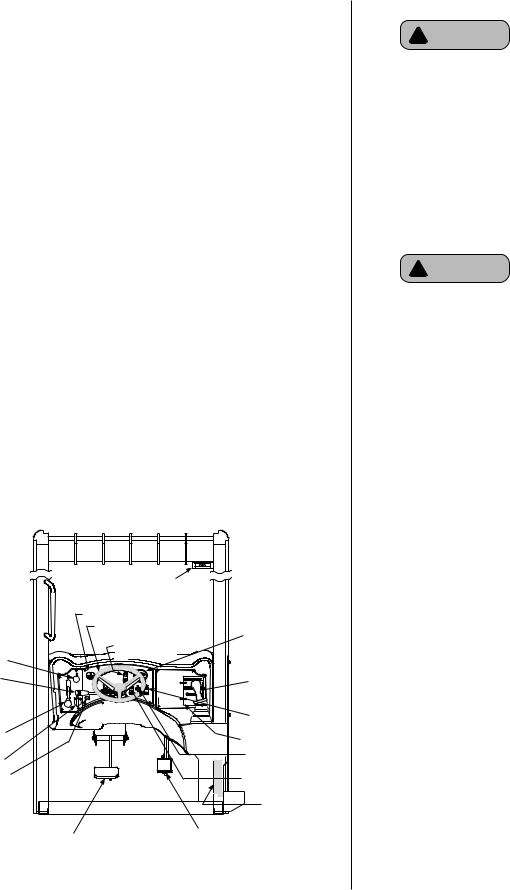
Pinch Points
Stay clear of pinch points and rotating parts on the material handler. Getting caught in a pinch point or a moving part can cause serious injury or death. Before performing any maintenance on machine, follow the “STANDARD SHUT-DOWN PROCEDURE” on page 1.1.
Front & Rear Steering Axles
Boom Holes
Boom |
Attachment Tilt Cylinder |
Carriage Forks |
Platform & Tires |
1.2
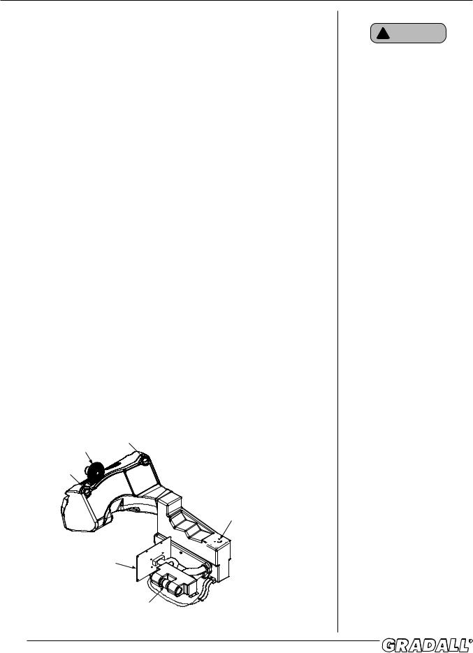
SAFETY HIGHLIGHTS
Fork Pin Area on Carriages
Form No. 20136 3/03 • TF6-42 Owner/Operator Manual
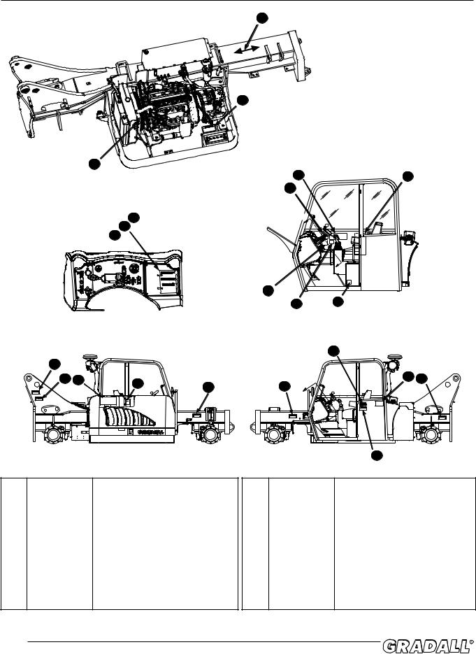
DECAL LOCATIONS
18
2
1
8 |
9 |
7
5 |
A |
4
3
|
|
|
|
|
|
|
A |
|
|
|
|
|
|
|
6 |
|
|
|
|
|
A-A |
|
|
11 |
10 |
|
|
|
|
|
|
|
|
15 |
|
|
12 |
|
|
|
|
|
|
|
|
13 |
17 |
14 |
13 |
|
13 A |
19 |
13 |
|
|
|
|
|
|
|||
|
|
|
|
|
|
|
||
|
|
|
|
|
|
A |
|
|
|
|
|
|
|
|
|
16 |
|
1 |
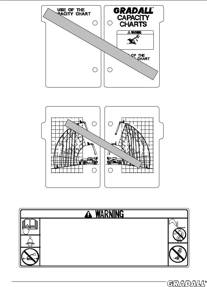
9150-3097 |
Warning Decal, moving parts |
9 |
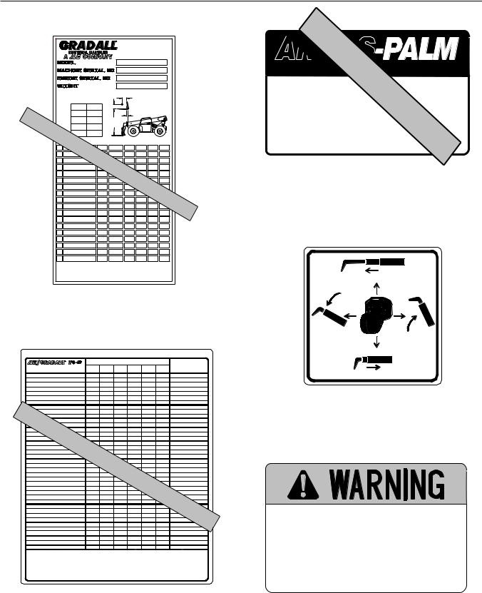
9150-3088 |
Serial No. & Attaching Plate |
|||
2 |
9150-3099 |
Warning Decal, battery |
|
10 |
9150-3112 |
Aux. Hyd. De-Press Decal |
||
3 |
9151-3207 |
Load Chart Cover |
|
11 |
9150-3102 |
Boom Operation Decal |
||
4 |
9150-3083 |
Carriage Chart - TF6-42 |
|
12 |
9150-3101 |
Inspection Decal |
|
|
5 |
9150-3084 |
Swing Carriage - TF6-42 |
|
13 |
9150-3108 |
Warning Decal, pinch point |
||
|
9150-3085 |
Swing Mast - TF6-42 |
|
14 |
9150-3107 |
Oil Level Decal |
|
|
|
9150-3086 |
Truss Boom - TF6-42 |
|
15 |
7733-3027 |
Made in USA Decal |
||
|
9150-3087 |
Platform Chart - TF6-42 |
|
16 |
9150-3109 |
Warning Decal, no riders |
||
6 |
9150-3096 |
Warning Decal, lifting personnel |
17 |
9150-3113 |
Service Instruction Plate |
|||
7 |
9150-3110 |
Danger Decal, high voltage |
18 |
1701529 |
Decal |
|
||
8 |
9150-3098 |
Warning Decal, operation |
19 |
7702-3008 |
Fuel Decal |
|
||
2.0
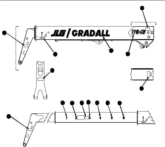
DECAL LOCATIONS
24
A
22
23
A |
25 |
|
A-A
26 27 24
22
20 |
9150-3128 |
TF6-42 Decal |
21 |
9147-3132 |
Gradall Decal |
22 |
9114-3282 |
Warning Decal, pinch point |
23 |
9100-3031 |
Boom Angle Decal |
24 |
9151-3210 |
Warning Decal, moving parts |
25 |
9150-3096 |
Warning Decal, lifting personnel |
|
|
|
B B
21
20
24
B-B
28 |
29 |
30 |
31 |
26 |
9100-3016 |
“1” Decal |
27 |
9100-3018 |
“2” Decal |
28 |
9112-3042 |
“3” Decal |
29 |
9100-3020 |
“4” Decal |
30 |
9112-3044 |
“5” Decal |
31 |
9116-3077 |
“6” Decal |
|
|
|
|
2.1 |
Form No. 20136 3/03 • TF6-42 Owner/Operator Manual |
DECALS
Instructions
SAMPLE |
|
|
TWO METHODS OF USING THE CAPACITY CHART. |
|
|
Method 1 |
|
|
1. The operator must determine: |
ONLY |
|
BOOM EXTENSION NUMBER where the load |
|
|
is to be placed. |
|
|
BOOM ANGLE where the load is to be |
|
|
placed. |
|
- |
2. On the capacity chart, find the arc for the boom |
|
|
|
USE |
|
extension number, and follow it down to the boom |
|
|
angle. |
|
|
3. The number in the load zone where these two cross |
|
|
is the maximum capacity for this lift. If the two cross |
|
|
at a division between zones, the smaller number |
|
|
must be used. |
|
|
Method 2
1. The operator must determine:
HEIGHT where the load is to be placed.
DISTANCE from the front of the machine where the load is to be placed.
2.On the capacity chart, find the line for the height and follow it over to the distance.
3.The number in the load zone where the two cross is the maximum capacity for this lift. If the two cross at a division between zones, the smaller number must be used.
For each method, the number in the load zone must be equal to or greater than the weight of the load to be lifted. Determine the limits of the load zone on the
capacity chart by boom angle AND boom extension number. Keep the load within theses limits.
9151-3207 REV.-
R
|
TIPOVER HAZARD. Failure to comply with |
||
|
instructions could result in death or serious |
||
|
injury. |
|
|
CHART |
IN |
|
|
The operator MUST: |
|
||
|
|
||
1. |
Make sure the handler is on a firm, level surface |
||
|
before lifting or placing a load. |
CAB |
|
2. |
|
|
|
Make sure that the capacity charts are for the |
|||
|
appropriate Gradall model. |
|
|
3. |
Make sure that the Part Numver shown on the |
||
|
attachment's Serial Number Plate matches the Part |
||
|
Number shown on the capacity chart. |
||
4. |
Be sure of the WEIGHT of the load to be lifted. |
||
9151-3207 REV.-
BACK |
FRONT |
Instructions
Located on dashboard
P/N 9151-3207
MODEL |
MODEL |
TF6-42 |
TF6-42 |
48' |
48' |
|
|
RATED CAPACITY @ 2 FT LOAD CENTER |
RATED CAPACITY @ 2 FT LOAD CENTER |
|
44' |
|
|
|
|
|
|
70° |
|
|
|
|
|
70° |
|
|
|
|
|
|
|
|
44' |
|
|
|
|
|
|
|
|
|
|
|
|
|
|
|
|
|
|
|
|
|
|
|
|
||
PILER |
40' |
|
|
|
|
60° |
|
|
6 |
|
|
|
6 |
|
|
60° |
|
|
|
|
|
40' |
|
|
36' |
|
|
50° |
|
|
|
|
5 |
|
|
|
5 |
|
|
|
|
50° |
|
|
|
|
36' |
72" |
|
72" |
|
|
|
|
|
|
|
|
|
|
|
|
|
|
|
|
|
|
|
|
||||
|
|
|
|
|
|
|
|
4 |
|
|
|
4 |
|
|
|
|
|
|
|
|
|
|
||
& |
|
|
|
|
|
|
|
|
|
|
|
|
|
|
|
|
|
|
|
|
|
& |
||
32' |
|
|
|
|
SAMPLE |
|
|
|
|
|
|
|
|
|
|
|
|
|
32' |
|||||
48" SLOPE |
|
|
|
|
1ONLY- |
|
|
3 |
|
|
|
|
|
|
|
|
|
48" CARRIAGES |
||||||
|
|
40° |
|
|
|
|
|
|
|
|
|
|
40° |
|
|
|
||||||||
|
|
|
|
|
LBS |
|
3 |
|
|
|
|
|
|
|
|
|
|
|
||||||
28' |
|
|
|
|
|
|
|
|
|
|
|
6000 |
|
|
|
|
|
|
|
28' |
||||
|
|
|
|
|
|
|
|
2 |
|
2 |
|
|
|
|
|
|
|
|
|
|
|
|||
|
24' |
30° |
|
|
|
LBS |
5000 |
LBS |
|
|
1 |
|
|
LBS |
5000 |
4000 |
|
|
30° |
|
24' |
|
||
|
|
|
|
|
LBS |
|
|
|
|
USE |
|
|
6600 |
|
|
|
|
|
|
|
|
|
||
|
20' |
|
|
LBS |
4000 |
|
6600 |
|
CHART |
|
|
LBS LBS 3000 |
|
|
|
|
20' |
|
||||||
|
|
|
3000 |
|
|
|
LBS |
|
2000 |
|
|
|
|
|||||||||||
|
20° |
|
LBS |
2000 |
|
|
|
|
|
|
|
|
|
|
LBS |
1200 |
20° |
|
|
|||||
|
|
|
|
|
|
|
|
|
|
|
|
|
16' |
|
||||||||||
|
16' |
|
|
|
|
|
|
|
|
|
|
|
|
|
LBS |
|
|
|
||||||
|
|
|
800 |
|
|
|
|
|
|
|
|
IN |
|
|
|
|
|
LBS |
|
|
12' |
|
||
|
12' |
|
|
|
|
|
|
|
|
|
CAB |
|
|
|
|
|
|
|||||||
|
10° |
|
|
|
|
|
|
|
|
|
|
|
|
|
|
|
10° |
|
|
|||||
|
8' |
|
|
|
|
|
|
|
|
|
|
|
|
|
|
|
|
|
8' |
|
||||
|
4' |
|
|
|
|
|
|
|
|
|
|
|
|
|
|
|
|
|
0° |
4' |
|
|||
|
0° |
|
|
|
|
|
|
|
|
|
|
|
|
|
|
|
|
|
|
|
||||
|
0' |
|
|
|
|
|
|
|
|
|
|
|
|
|
|
|
|
|
|
|
|
|
0' |
|
|
-4' -9° |
|
|
|
|
|
|
|
|
|
|
|
|
|
|
|
|
|
|
|
|
-9° |
-4' |
|
|
-8' 32' |
28' |
24' |
20' |
16' |
12' |
8' |
4' |
0' |
|
|
|
0' |
4' |
8' |
12' |
16' |
20' |
24' |
28' |
32' |
-8' |
|
|
|
USE WITH: |
|
|
|
|
|
|
|
|
USE WITH: |
|
|
|
|
|
|
|
|
|
|
|
|
||
|
|
|
|
|
|
|
|
|
9140-5073 48" CARRIAGE |
|
|
|
|
|
|
|
|
|
|
|
||||
|
9140-5101 48" SLOPE PILER CARRIAGE |
|
|
|
9140-5074 72" CARRIAGE |
|
|
|
|
|
|
|
|
|
|
|
||||||||
|
9140-5079 72" SLOPE PILER CARRIAGE |
|
|
|
9140-5077 72" DRYWALL CARR. (4,000 LB MAX. CAPACITY) |
|
|
|
|
|||||||||||||||
|
|
|
|
|
|
|
|
|
|
|
9140-5054 60" 3/4 YD. BUCKET (4,500 LB MAX. CAPACITY) |
|
|
|
|
|
||||||||
|
|
|
|
|
|
|
|
|
|
|
9140-5055 74" 1 1/4 YD. BUCKET (4,500 LB MAX. CAPACITY) |
|
|
|
|
|||||||||
|
|
|
|
|
|
|
|
|
|
|
9140-5071 102" 1 1/4 YD. BUCKET (4,500 LB MAX. CAPACITY) |
|
|
|
|
|||||||||
|
|
|
|
|
|
|
|
|
|
9150-3083 (-) |
|
|
|
|
|
|
|
|
|
|
|
9150-3083 (-) |
|
|
|
|
|
|
|
|
|
|
BACK |
|
|
|
|
|
|
|
|
FRONT |
|
|
|
|
|||
|
|
|
|
|
|
|
|
|
Located on dashboard |
|
|
|
|
|
|
|
|
|
|
|||||
|
|
|
|
|
|
|
|
|
|
P/N 9150-3083 |
|
|
|
|
|
|
|
|
|
|
|
|||
For safe operation of machine, and to minimize risk of s e r i o u s i n j u r y, R E A D A N D O B S E RV E t h e f o l l o w i n g :
1.Only trained and authorized personnel may operate this machine.
2.Before operating, read and understand all capacity charts, operator manual and safety manuals.
3.Operator must be seated with seat belt fastened. Assure all controls are in neutral before ignition switch is turned on.
4.Do not travel with boom raised. When traveling, fully retract boom and place forks in carry position, which is approximately 4 feet (1.2 m) above ground. Tilt carriage back slightly to cradle load. Use extreme caution when turning.
5.On inclines, travel with load up-grade.
6.Keep others away from machine when operating. Do not allow others to stand under boom or load. Always look in direction of travel.
7.Use extreme care when handling long, high or wide loads. Do not handle unstable or loosely stacked loads.
8.Forks must be centered under load, and spaced apart as far as possible.
9.Level machine before lifting any load above 4 feet (1.2m).
10.Improper use of machine could result in machine tipping over. If machine starts to tip over, do not leave operator's seat. Lean away from tip, and brace yourself.
11.Keep mirror(s) clean and properly adjusted. Objects in mirror(s) are closer than they appear.
9150-3098 REV. A
Located on right cab wall
P/N 9150-3098
2.2
DECALS
|
|
|
|
|
|
|
|
|
GRADALL IS A REGISTERED TRADEMARK |
||
|
|
|
|
|
|
|
|
|
FOR HYDRAULIC EQUIPMENT |
||
|
|
|
|
|
|
|
|
|
BUILT BY THE JLG COMPANY |
||
|
|
|
|
|
|
|
|
|
1 JLG DRIVE, McCONNELLSBURG, PA. |
||
|
|
|
|
|
|
|
|
|
|
U.S.A. |
|
|
|
|
|
|
|
|
|
|
TF6-42 |
|
|
|
ATTACHMENTS) |
|
|
|
|
|
20280 LBS |
|
|||
|
(WITHOUT |
|
|
|
|
|
|
|
|
|
|
AS RELEASED FROM FACTORY THIS TRUCK MEETS THE DESIGN SPECIFICATIONS |
|
||||||||||
ESTABLISHED IN AMERICAN NATIONAL STANDARDS FOR POWERED INDUSTRIAL |
|
||||||||||
TRUCKS PART III ASME B56.6b-1998. |
|
C |
|
|
|
|
|||||
|
CAPACITY WITH STANDARD |
|
|
|
|
|
|||||
|
48" & 72" CARRIAGE. |
|
|
|
|
|
|
|
|||
CAP# |
6.6 |
|
1.2 |
|
B |
|
|
|
|
|
|
X1000 |
|
|
|
|
|
|
|
|
|
|
|
A |
42' |
|
4.6' |
|
|
|
|
D |
|
|
|
SAMPLEWITH |
ATTACHMENT |
|
|
1000 |
WEIGHT |
|
A |
C |
D |
||
|
|
|
B |
||||||||
B |
24" |
|
24" |
|
A |
|
|
|
|
|
|
C |
24" |
|
24" |
|
|
|
|
|
|
|
|
D |
2.0' |
|
26.9' |
|
|
|
|
|
|
||
SHIPP D |
ONLY |
|
CAP# |
TRUCK & |
|
|
|
|
|
||
|
|
|
|
|
ATTACHMENT |
|
|
|
|
||
48" CARRIAGE |
|
|
|
6.6 |
21,030 |
42' |
24" |
24" |
2.0' |
||
P/N 9140-5073 |
* |
|
|
||||||||
72" CARRIAGE |
|
|
|
6.6 |
21,140 |
42' |
24" |
24" |
2.0' |
||
P/N 9140-5074 |
* |
|
|
||||||||
|
|
|
|
|
USE |
|
|
|
|
|
|
48" SLOPE PILER |
|
- |
21,310 |
42' |
24" |
24" |
2.7' |
||||
P/N 9140-5101 |
* |
|
|
6.6 |
|||||||
72" SLOPE PILER |
|
|
|
|
CHART |
|
|
||||
P/N 9140-5079 |
* |
|
|
6.6 |
21,500 |
42' |
24" |
24" |
2.7' |
||
60" 3/4 YD BUCKET |
|
|
4.5 |
20,780 |
42' |
--- |
--- |
4.3' |
|||
P/N 9140-5054 |
** |
|
|
||||||||
74" 1 1/4 YD BUCKET |
|
|
4.5 |
20,960 |
42' |
--- |
--- |
4.9' |
|||
P/N 9140-5055 |
** |
|
|
||||||||
102" 1 1/4 YD BUCKET |
|
|
4.5 |
21,000 |
42' |
--- |
--- |
4.3' |
|||
P/N 9140-5071 |
** |
|
|
||||||||
10FT TRUSS BOOM |
|
|
2.0 |
20,830 |
52' |
--- |
IN--- |
3.8' |
|||
P/N 9140-5083 *** |
|
|
|||||||||
10FT TRUSS BOOM W/WINCH |
|
2.0 |
21,010 |
52' |
--- |
--- |
3.8' |
||||
P/N 9140-5081 *** |
|
|
|||||||||
15FT TRUSS BOOM |
|
|
2.0 |
20,950 |
57' |
--- |
--- |
CAB4.3' |
|||
P/N 9140-5082 *** |
|
|
|||||||||
15FT TRUSS BOOM W/WINCH |
|
2.0 |
21,140 |
57' |
--- |
--- |
4.3' |
||||
P/N 9140-5080 *** |
|
|
|||||||||
6FT MAST W/48" CARR. |
|
|
6.0 |
22,000 |
39' |
24" |
24" |
1.9' |
|||
P/N 9140-5060 |
* |
|
|
||||||||
6FT MAST W/72" CARR. |
|
|
6.0 |
22,100 |
39' |
24" |
24" |
1.9' |
|||
P/N 9140-5061 |
* |
|
|
||||||||
6FT SWING MAST |
|
|
4.0 |
22,880 |
48' |
24" |
24" |
4.2' |
|||
P/N |
9140-5070 **** |
|
|
||||||||
72" 100° SWING CARR. |
|
|
6.0 |
21,800 |
31' |
24" |
24" |
4.4' |
|||
P/N 9140-5075 |
* |
|
|
||||||||
WORK PLATFORM |
|
|
1.8 |
21,040 |
42' |
--- |
--- |
4.7' |
|||
P/N |
9141-5025 ***** |
|
|
||||||||
*WEIGHTS ARE BASED ON USING 2 X 4 X 48" FORKS (APPROX. 268# PER PAIR) |
|
|
|||||||||
**BUCKET DIMENSIONS (A & D) REFER TO BUCKET LIP HEIGHT. |
|
|
|
|
|||||||
***TRUSS BOOM DIMENSIONS (A & D) REFER TO HOOK CENTER. |
|
|
|
|
|||||||
****WEIGHT IS BASED ON SP'L SWING MAST FORKS (APPROX. 230# PER PAIR) |
|
|
|||||||||
*****PLATFORM DIMENSIONS (A & D) REFER TO CENTER OF FLOOR. |
|
|
|
||||||||
FORKS RATED LESS THAN THE ATTACHMENT CAPACITY SHOWN ABOVE DECREASE |
|
|
|||||||||
CAPACITY OF ATTACHMENT TO THAT OF FORKS. FORKS RATED MORE THAN |
|
9150-3088 (A) |
|||||||||
ATTACHMENT CAPACITY DO NOT INCREASE ATTACHMENT CAPACITY. |
|
|
|||||||||
Located on right cab wall
P/N 9150-3088
LUBRICATION AND MAINTENANCE
|
|
SERVICE INTERVALS |
|
|
LUBRICANT TYPE |
|||
MATERIAL HANDLER |
DAILY |
WEEKLY |
EVERY 5 |
3 MO. |
6 MO. |
YEARLY |
OR |
|
OR |
OR |
WKS OR |
OR |
OR |
|
OR |
SPECIFICATION |
|
|
10 HRS |
50 HRS |
250 HRS |
500 HRS |
1000 HRS |
1500 HRS |
|
|
Diesel Engine |
|
|
|
|
|
|
|
|
Air Cleaner Element |
Check |
|
|
|
|
|
|
|
Fuel Filter |
|
|
|
Change |
|
|
|
|
Engine Oil Filter |
|
|
Change |
|
|
|
|
|
Engine Oil |
Check |
|
Change |
|
|
|
|
SAE 15W-40 CE Oil |
Coolant |
|
Check |
|
|
|
Change |
Etheylene Glycol |
|
Diesel Fuel |
Fill |
|
|
|
|
|
|
No. 2 Diesel Fuel |
Transmission |
|
|
|
|
|
|
|
|
Lubricant |
Check |
|
|
|
Change |
|
|
Mobil 424 |
Filter |
|
|
|
|
Change |
|
|
|
Transfer Case |
|
|
|
|
|
|
|
|
Lubricant |
|
|
Check |
|
Change |
|
|
Mobil 424 |
Axle Lubricant |
|
|
|
|
|
|
|
|
Center Section |
ONLY |
|
Check |
|
Change |
|
|
Mobil 424 |
Planetary Hubs |
|
Check |
|
Change |
|
|
Mobil 424 |
|
HydraulicSAMPLESystem |
|
|
|
|
|
Change |
|
|
Lubricant |
Check |
|
|
|
|
Mobil 424 |
||
Filter |
Check |
- |
|
|
|
Change |
|
|
Breather/Filter |
|
|
|
|
Change |
|
||
Grease Fittings |
|
Grease |
|
|
|
|
Mystik Tetrimoly |
|
Axles (6 Pts. Ea.) |
|
|
CHART |
|
||||
Boom Head Pivot (2 Pts.) |
|
Grease |
|
|
Mystik Tetrimoly |
|||
Boom Pivot (2 Pts.) |
|
GreaseUSE |
|
|
|
|
Mystik Tetrimoly |
|
Cylinder Pins(13 Pts.) |
|
Grease |
|
|
|
|
|
Mystik Tetrimoly |
Drive Shafts (1 Pt. Ea.) |
|
|
Grease |
|
|
|
|
Mystik Tetrimoly |
Extend Chain Sheave (1 Pt.) |
|
Grease |
|
|
|
|
IN |
Mystik Tetrimoly |
Quick Switch Pin (1 Pt.) |
|
Grease |
|
|
|
|
Mystik Tetrimoly |
|
Retract Chain Sheave (1 Pt.) |
|
Grease |
|
|
|
|
Mystik Tetrimoly |
|
Stabilizer Cylinder (3 Pts.) |
|
Grease |
|
|
|
|
Mystik Tetrimoly |
|
Boom |
|
|
|
|
|
|
|
|
Front Bottom Bearing Pads |
|
Grease |
Check |
|
|
|
|
Mystik Tetrimoly |
All Other Bearing Pads |
|
|
Grease |
|
|
|
|
CABMystik Tetrimoly |
Extend/Retract Chains |
|
|
Check |
|
|
|
|
See Manual |
Options And Attachments |
|
|
|
|
|
|
|
|
Work Platform Pins |
|
Grease |
|
|
|
|
|
Mystik Tetrimoly |
Attachment Pivots And Pins |
|
Grease |
|
|
|
|
|
Mystik Tetrimoly |
Tires |
|
|
|
|
|
|
|
|
13.00-33.5 12 PLY LSW G-2 |
|
Check |
|
|
|
|
|
65 PSI (448 kPa) |
Lug Nut Torque |
|
|
|
Torque |
|
|
|
350-400 Lb-Ft (39-45 Nm) |
Use this chart in conjunction with the "Lubrication & Maintenance" and "Recommended |
|
Lubricants & Capacities" sections of the Owner/Operator Manual. |
|
Service intervals may need to be more frequent than those shown depending upon |
|
application severity. Consult your Gradall dealer for recommendations. |
|
It is recommended that engine oil and filter, transmission lubricant and filter, |
|
transfer case lubricant and axle lubricant be changed after first 100 hours on |
|
new, or rebuilt units. |
9150-3113 REV - |
Located inside engine cover
P/N 9150-3113
Box 61 |
SAMPLE |
SD 57201 |
|
|
|
||
GRADALL MATER |
|
06 / 9 / 10 |
|
MAX WEIGHT : 2150 |
ONLY |
||
|
|
||
MEETS SAE : J1040 MA
MEETS ISO : 3471 (94) / 3
MEETS ANSI : B56.6 - 8.16 / P
GRADALL : 9114-3261 SERIAL : 8
Located on back wall, behind operator’s seat
P/N N/A (enclosed cab) P/N N/A (open cab)
9150-3102 REV. -
Located on right cab wall
P/N 9150-3102
THE PROTECTION OFFERED BY THIS ROPS WILL BE IMPAIRED IF IT HAS BEEN SUBJECTED TO ANY MODIFICATION, STRUCTURAL DAMAGE, OR HAS BEEN INVOLVED IN AN OVERTURN INCIDENT. THIS ROPS MUST BE REPLACED AFTER A ROLL-OVER. SEAT BELTS MUST BE WORN WHILE OPERATING VEHICLE.
000850
Located on left side, front cab plate P/N 9116-4094
|
2.3 |
Form No. 20136 3/03 • TF6-42 Owner/Operator Manual |
DECALS
|
|
|
|
|
|
|
|
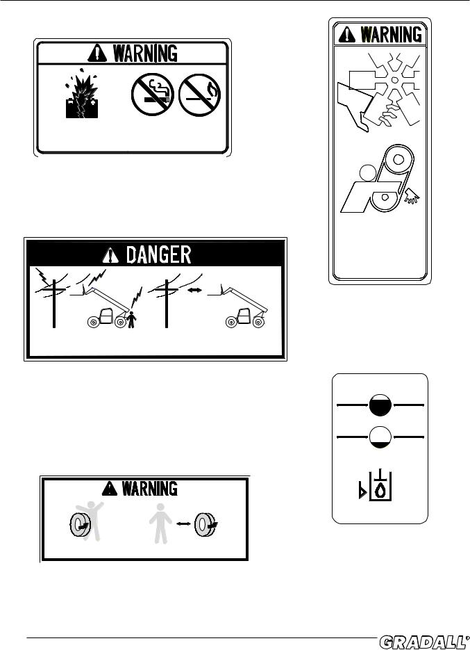
Batteries produce EXPLOSIVE |
Keep sparks, flames and lighted |
||
GASES. EXPLOSION could |
materials away from batteries. |
||
result in serious injury. |
|
|
9150-3099 REV - |
|
|
|
|
|
|
|
|
Located in engine compartment
P/N 9150-3099
|
10 FT. |
|
|
(3 M) |
|
CONTACTING ELECTRIC POWER |
Do not place machine or load |
|
within 10 feet (3m) of electric |
||
LINES will result in death |
||
power lines. |
||
or serious injury. |
||
|
9150-3110 REV - A
MOVING PARTS can cut or entangle. Keep clear while engine is running.
9150-3097 REV. -
Located in engine compartment P/N 9150-3097
Located on right cab wall
P/N 9150-3110
|
|
|
|
|
|
|
|
|
|
|
|
|
|
|
|
|
|
|
|
|
|
|
|
|
MOVING PARTS COULD CRUSH, |
KEEP CLEAR OF WHEELS AND MOVING PARTS |
|||||
|
CAUSING DEATH OR SERIOUS INJURY. |
WHILE ENGINE IS RUNNING. |
|||||
|
|
|
|
|
9150-3108 REV - |
||
|
|
|
|
|
|
|
|
Located on right and left frame, front & rear
P/N 9150-3108
2.4
9150-3107
Located on hydraulic reservoir P/N 9150-3107
DECALS
R
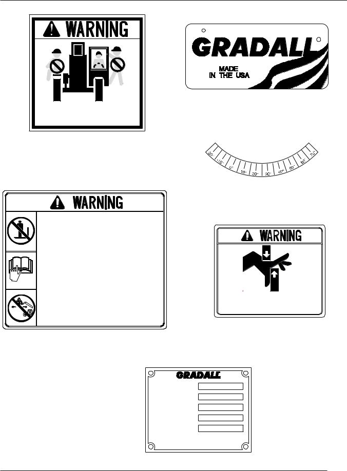
7733-3027
Located on left outside cab wall
P/N 7733-3027
NO RIDERS. Riders could FALL OFF machine causing death or serious injury.
9150-3109 REV -
Located on left cab outside wall
P/N 9150-3109
Located on left side of boom
P/N 9100-3031
When lifting personnel, USE ONLY a Gradall manufactured personnel work platform.
READ AND UNDERSTAND personnel work platform Owner/Operator manual before lifting personnel.
DO NOT DRIVE machine from cab when personnel are on platform.
All personnel on platform must WEAR A FULL BODY HARNESS, with lanyard attached to a designated anchorage point.
OPERATE CONTROLS CAUTIOUSLY and lightly when lifting or positioning personnel.
IN ADDITION, when using a personnel work platform WITHOUT CONTROLS:
Do not use personnel work platform without proper
CAPACITY CHART DISPLAYED in cab.
When personnel are on platform, the OPERATOR MUST REMAIN SEATED in cab with personnel in direct line of sight.
Failure to comply could result in death or serious injury.
9150-3096 REV A
Located on boom head, and inside right cab wall P/N 9150-3096
406 MILL AVE. S.W. NEW PHILADELPHIA, OHIO
ATTACHMENT
SERIAL NUMBER
WEIGHT
CAPACITY
HYD. PRESSURE
MOVING PARTS could cut or crush causing death or serious injury. Keep clear of moving parts while engine is running.
9151-3210 REV -
Located on boom
P/N 9151-3210
MADE IN U. S. A.
|
THE CAPACITY OF FORKLIFT, ATTACHMENT AND FORK |
|
|
COMBINATION MAY BE LESS THAN THE CAPACITY SHOWN |
|
|
ON ATTACHMENT - CONSULT FORKLIFT NAMEPLATE |
|
|
AND ALSO INSURE FORKS ARE OF PROPER SIZE. |
|
|
9015-3001 |
|
|
Located on attachment |
|
|
P/N 9015-3001 |
2.5 |
Form No. 20136 3/03 • TF6-42 Owner/Operator Manual |
|
DECALS
Located on Frame
P/N 1701529
DIESEL FUEL
Located on outside of Cab
P/N 7702-3008
2.6
FIRST |
ANSI REQUIRES AN ANNUAL INSPECTION |
5 YEARS |
|
DELIVERY |
|||
|
BE PERFORMED BY QUALIFIED PERSONNEL |
|
|
|
IN ACCORDANCE WITH MANUFACTURER'S |
|
|
|
SPECIFICATIONS. |
|
|
1 YEAR |
USE GRADALL APPROVED MANUALS, PARTS |
6 YEARS |
|
|
|
||
|
AND PROCEDURES. CONTACT GRADALL |
|
|
2 YEARS |
REGARDING STRUCTURAL REPAIRS. |
7 YEARS |
|
|
|||
|
STAMP FRAME WITH MONTH/DAY/YEAR |
|
|
|
NEXT TO ARROW AFTER EACH |
|
|
3 YEARS |
INSPECTION RETAIN RECORDS IN |
8 YEARS |
|
ACCORDANCE WITH ANSI. |
|||
|
|
||
4 YEARS |
NOTIFY GRADALL IMMEDIATELY OF ANY |
9 YEARS |
|
CHANGES OF OWNERSHIP. |
|||
|
REPLACE IF DEFACED |
10 YEARS |
|
|
9150-3101 REV - |
|
|
|
|
|
Located on Boom Pivot Frame P/N 9150-3101
OPERATOR’S CAB |
|||
|
|
|
|
OPERATOR’S CAB |
|
|
|
The cab permits vision from all sides and includes an overhead guard to |
! WARNING |
||
provide protection from falling objects. |
|||
A fully-enclosed cab with windows and a lockable door is available as an option. |
Never operate the handler unless |
||
the overhead guard is in good |
|||
The top half of the cab door must be secured in either the fully-opened or |
|||
condition. |
|||
closed position. The bottom half of the cab door must be secured in the closed |
|||
|
|
||
position only. Be sure the door is fully secured when operating the handler. |
|
|
|
The operator’s seat is equipped with a seat belt and includes fore and aft adjustment to compensate for variations in operator size. The adjustment release/lock is located on the side of seat. Wear seat belt when operating machine.
An optional windshield wiper/washer is available for use with enclosed cabs. A control switch is located on the instrument panel.
A variable-speed defroster fan is available for use with enclosed cabs. An “On/ |
! WARNING |
|
Off” control switch and speed control are located on the base of the fan. |
||
The heater fan speed is controlled by a knob on the panel to the right of the |
Any modification to this machine |
|
must be approved by JLG/GRADALL |
||
operator’s seat. Hot water to the heater can be controlled by a knob on the |
||
to assure compliance with FOPS/ |
||
same panel or a valve in the engine compartment. |
||
ROPS certification for this cab/ |
||
|
||
The operator’s cab is an S.A.E. “FOPS/ROPS” structure. Do not make |
machine configuration. |
|
|
||
any modification to this structure. If damaged, the cab cannot be |
NOTE! |
|
repaired. It must be replaced. |
||
|
||
CONTROL AND INSTRUMENT IDENTIFICATION |
Relevant S.A.E. Recommended |
|
Practices: |
||
Figure 3-1 |
S.A.E. J1040 for ROPS |
|
|
S.A.E. J231 for FOPS |
LEVEL |
|
|
INDICATOR |
|
|
HOURMETER |
|
|
STEERING |
|
|
WHEEL |
OIL PRESSURE/ |
|
PARK BRAKE |
COOLANT TEMP/ |
|
VOLTMETER/ |
||
SWITCH |
||
FUEL GAUGE |
||
EMERGENCY STOP SWITCH |
||
|
||
TRANSMISSION |
BOOM CONTROL |
|
CONTROL LEVER |
||
JOYSTICK |
||
(FORWARD/REVERSE/GEAR |
||
CHANGE LEVER) |
|
|
|
HORN BUTTON |
AUX CONTROL LEVER |
|
CAPACITY CHARTS |
(OPTIONAL) |
|
|
CONTROL STATION |
|
START/AUX. POWER |
SELECTOR SWITCH |
|
SWITCH |
TRANS TEMP WARNING LIGHT |
|
STEER SELECT SWITCH |
|
|
|
|
|
MICROPROCESSOR |
|
|
CONTROLLER |
|
BRAKE PEDAL |
ACCELERATOR PEDAL |
|
|
|
3.0 |
Form No. 20136 3/03 • TF6-42 Owner/Operator Manual |
OPERATOR’S CAB
Accelerator Pedal: Depress pedal to increase speed and release pedal to decrease speed.
Attachment Tilt Lever: This lever controls tilt of the fork carriage. Speed is proportional to lever actuation and engine RPM. Push lever forward to tilt down; pull lever back to tilt up.
Attachment Tilt Switch (optional): Depress left side of switch to tilt down; depress right side of switch to tilt up.
Auxiliary Control Lever (optional): This lever is used to control optional hydraulic attachments. Follow decal instructions for lever/handler movements.
Auxiliary Light Switch (optional): This switch turns auxiliary lights on and off.
Boom Control Joystick: This joystick controls boom elevation and extension. Pull joystick back to raise boom; push joystick forward to lower boom. Move joystick to right to extend boom; move to left to retract boom. Speed of boom movement is proportional to joystick actuation and engine RPM.
Control Station Selector Switch: Rotate key activated switch to “Platform” to transfer power to platform controls. Rotate key activated switch to “Cab” to transfer power to cab controls. When not in use, turn the selector switch to “Off”. If the switch is not positioned in the “Off” position during shutdown and emergency stop button is in run mode, the battery will drain.
Decompression Valve: Used only for connecting/disconnecting Auxiliary Hydraulics. Located in cab, left side of seat pedestal.
Emergency Stop Button: Pushing the button stops engine operation.
Engine Coolant Temperature Gauge: This gauge displays engine coolant temperature.
Engine Oil Pressure Gauge: This gauge displays engine oil pressure.
Fuel Gauge: This gauge displays level of fuel in fuel tank.
Heater Fan Switch (optional): This switch turns heater fan on and off.
AIR VENT
DEFROSTER FAN
AIR VENT
TEMPERATURE CONTROL
 HEATER FAN SWITCH
ACCESS COVER/
HEATER VENT
HEATER
Horn Button: Depress button to sound horn.
3.1
! WARNING
A brief description of controls and instruments is provided here as a convenience for the operator. These descriptions DO NOT provide complete operation instructions. Read & understand this Manual, the Transformer Series Work Platform Manual, the ANSI A92.5 Responsibilities Manual, the EMI Aerial Work Platform Safety Manual, and the GRADALL Material Handler Safety Manual.
OPERATOR’S CAB
Hourmeter: This meter indicates total time of engine operation in hours and tenths of hours.
Start/Aux. Switch: The control selector switch must be in cab position for start/ aux. switch to be operational. Momentarily push switch up to start engine. With engine off, simultaneously push switch down and activate controls to activate auxiliary power.
Level Indicator: This bubble level indicator enables the operator to determine the left to right level condition of the handler.
Lights Switch (optional): This switch controls optional lighting which may be provided with the handler.
Machine Level Lever: This lever controls the relationship of the handler frame to the front axle. Move the lever left to tilt frame to left, move the lever right to tilt frame to right.
Microprocessor Controller: This unit processes information for the transmission.
Neutral Lock Lever: The transmission control lever is equipped with a switch that locks the transmission control lever in neutral when activated.
Parking Brake Switch: This switch controls the application and release of the parking brake. Indicator light on switch glows (red) to indicate brake is applied.
Seat lock Release Lever: This lever unlocks and locks seat position adjustment.
Service Brake: This pedal operates the service brakes. The further the pedal is depressed, the slower the travel speed. Full depression of pedal causes full service brake application.
Steer Select Switch: This switch has three positions to allow selection of 4-wheel circle steer, 4-wheel crab steer and 2-wheel steer. 4-wheel circle steer allows the front and rear wheels to steer in opposite directions for tight turns. 4-wheel crab steering turns the front and rear tires in the same direction for moving the machine to the side. 2-wheel steer allows only the front wheels to steer.
Steering Wheel: The steering wheel controls the angle of wheels. Turning the steering wheel to the right causes a right turn. Turning the steering wheel to the left causes a left turn.
Transmission Control: This lever engages forward or reverse travel. Push lever fully forward for forward travel; pull lever fully backward for reverse travel. Move lever to centered position for “Neutral.” Twist hand grip to select gear.
Transmission Temperature Light: This light will illuminate during starting procedure for a bulb check. If transmission temperature exceeds 250° light will glow indicating the need for service.
Voltmeter: This gauge indicates alternator output and battery condition.
4-Wheel Circle Steer
4-Wheel Crab Steer
2-Wheel Front Steer
! CAUTION
If transmission temperature light glows, move material handler to a safe location and shut down.
! CAUTION
When traveling at higher speeds use 2-wheel front steering.
|
3.2 |
Form No. 20136 3/03 • TF6-42 Owner/Operator Manual |
CHECKS & SERVICES BEFORE STARTING ENGINE
To be performed at the beginning of each work shift.
PERFORM “WALK-AROUND INSPECTION” AS DESCRIBED ON PAGES P6.2 & P6.3 IN THE TRANSFORMER SERIES WORK PLATFORM MANUAL LOCATED IN THE BACK OF THIS MANUAL. THIS INSPECTION IS A DAILY REQUIREMENT BEFORE OPERATING THIS MACHINE.
•Check to be sure the material handler is equipped with the proper load/ capacity chart and that it is legible before operating.
•If spark arrestors are required, be sure they are in place and in good working order.
•Check to be certain that windows and mirror(s) are clean and undamaged. Also make certain that mirror(s) are properly adjusted for operator’s view.
•Before removing filler caps or fill plugs, wipe all dirt and grease away from the ports. If dirt enters these ports, it can severely reduce component life.
•When adding fluids, refer to lubrication section of Manual to determine proper type.
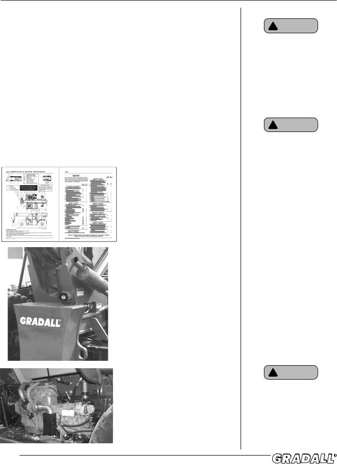
Complete all required maintenance before operating unit.
Service the unit in accordance with the “Lubrication and Routine
Maintenance” schedule, pages 19.2 and 19.3.
Inspect all structural members, including attachment, for signs of damage.
Inspect unit for obvious damage, vandalism and necessary maintenance. Check for signs of fuel, lubricant, coolant and hydraulic leaks. Open all access doors and look for loose fittings, clamps, components and attaching hardware. Replace hydraulic lines that are cracked, brittle, cut or which show signs of leakage or abrasion.
(Optional Turbo Charged Engine Shown)
4.0
! WARNING
Use extreme caution when checking items beyond your normal reach. Use an approved safety ladder.
! WARNING
Before operating handler, complete all required maintenance. Replace or repair all damaged, worn or missing components before starting or operating. Failure to properly maintain handler could cause serious injury or death.
! WARNING
Use a piece of cardboard or paper to search for leaks. DO NOT use bare hands. If anyone is injured by hydraulic fluid, including penetration of the skin, obtain medical help immediately!

PRE-START & FUNCTION CHECKS
To be performed at beginning of each work shift.
PERFORM “WALK-AROUND INSPECTION” AS DESCRIBED ON PAGES P6.2 & P6.3 IN THE TRANSFORMER SERIES WORK PLATFORM MANUAL LOCATED IN THE BACK OF THIS MANUAL. THIS INSPECTION IS A DAILY REQUIREMENT BEFORE OPERATING THIS MACHINE.
The safety, efficiency and service life of your handler will be increased by performing the operational checks listed below. Items preceded by an asterisk
(*) are optional and may not be furnished on your machine.
Before entering the operator’s cab, check:
1.Engine oil level.
2.Hydraulic oil level.
3.Air Filter Restriction Indicator. If needle is in red area, filter is clogged and element must be cleaned or changed.
During warm-up period, check:
*4. Heater, defroster and windshield wiper.
*5. Operating lights and rotating beacon.
6. Voltmeter-should show 13.5 to 14 volts.
When engine warms to operating range, check:
7.Transmission fluid level.
8.Service brake and parking brake.
9.Forward and reverse travel.
10.Each of the gear ranges.
11.Steering (in both directions) with engine at low idle. Check in each steering mode.
12.Horn and back-up alarm. Must be audible from inside operators cab with engine running.
13.All boom and attachment functions - operate smoothly and correctly.
14.Hydraulic Filter Condition Indicator - observe engine coolant temperature gauge after starting normal operation. When needle has been in operating range for an hour or so, stop handler in a safe area, apply parking brake, lower forks fully, shift forward/reverse lever to “Neutral” position and chock wheels. With engine running at full throttle, have an assistant check the Hydraulic Filter Condition Indicator. When bar gauge is in red area, filter is clogged and hydraulic oil is bypassing filter. Filter element must be changed before reaching bypass condition (change before needle reaches red area).
Complete all required maintenance before operating unit.
! WARNING
Check all tires and rims periodically for damage due to impact. Replace before use if damage is detected.
! CAUTION
Keep engine cover closed while engine is running except when checking Transmission Oil Level and hydraulic filter condition indicator.
! CAUTION
Continued operation with hydraulic fluid bypassing the filter may cause severe damage to hydraulic system components.
|
5.0 |
Form No. 20136 3/03 • TF6-42 Owner/Operator Manual |

ENGINE OPERATION
Starting the Engine
1.Make sure all controls are in “Neutral” and all electrical components (lights, heater, defroster, etc.) are turned off. Set parking brake.
2.Depress accelerator pedal approximately 1/4 to 1/3 of travel from top.
3.Turn control station selector switch to cab, pull up emergency stop, and push up on start/aux. switch to engage starting motor. If engine fails to start within 20 seconds, release start/aux. switch and allow starting motor to cool for a few minutes before trying again.
4.After engine starts, observe oil pressure gauge. If gauge remains on zero for more than ten seconds, stop engine and determine cause. Correct malfunction before restarting engine. Minimum pressure at operating temperature:
Low idle: 10 PSI (69kPa)
5.Warm up engine at approximately 1/2 throttle until engine coolant temperature reaches operating range.
Cold-Weather Starting Aids
In cold weather situations, a supplemental starting aid may be required. Gradallapproved starting aids employ ether. If your handler is equipped with an ether starting aid, the following applies:
•All employed ether is triggered by temperature gauge located on engine.
•At start-up, temperature gauge on engine will detect if ether is needed. Follow normal start-up procedure, shown above.
•Ether is employed and additional will be released if needed, to keep engine running.
•A second battery is added for additional cold-cranking capacity.
Battery-Boosted Starting
If you ever have to battery-boost start (jump-start) your handler, proceed as follows:
•Never allow vehicles to touch
•Connect the positive (+) jumper cable to positive (+) post of discharged battery
•Connect opposite end of positive (+) jumper cable to positive (+) post of booster battery
•Connect the negative (-) jumper cable to negative (-) post on booster battery
•Connect opposite end of negative (-) jumper cable to ground point on machine away from discharged battery
•Follow standard starting procedures
•Remove cables in reverse order after machine has started
6.0
! WARNING
Operator must be seated with seat belt fastened, transmission control lever in “Neutral” position, parking brake applied and all hydraulic controls in “Neutral” before starting engine.
NOTE!
Engine will not start unless transmission control lever is in “Neutral” and parking brake switch is applied.
! CAUTION
If your machine is equipped with a cold start aid, do not spray additional ether into air cleaner.
If machine is not equipped with cold start aid, follow instructions listed in the engine manual supplied with machine.

ENGINE OPERATION
Normal Engine Operation
Observe gauges frequently to be sure all engine systems are functioning properly.
The voltmeter shows the “charge/discharge” state of the battery charging system. With the engine running, meter should indicate 13.5 to 14 volts. With engine stopped, meter indicates battery charge (12 volts).
Be alert for unusual noises or vibration. When an unusual condition is noticed, park machine in safe position and perform standard shut-down procedure. (See Page 1.1) Report condition to your supervisor or maintenance personnel.
Avoid prolonged idling. Idling causes engine temperature to drop and this permits formation of heavy carbon deposits and dilution of lubricating oil by incompletely-burned fuel. If the engine is not being used, turn it off.
Stopping the Engine
•To stop engine, perform standard shut-down procedure shown on page 1.1.
•Operate engine at low idle for 3 to 5 minutes before turning it off. This allows engine coolant and lubricating oil to carry excessive heat away from critical engine areas, including turbocharger.
•Do not “gun” engine before shut down: This practice causes incompletelyburned fuel to remove oil film from cylinder walls and dilute lubricant in crankcase.
|
6.1 |
Form No. 20136 3/03 • TF6-42 Owner/Operator Manual |

BRAKE SYSTEM
General
The brake system includes a service brake and a parking brake. Service and parking brakes are applied through wet disc brake packs located within axle housing.
Service Brakes
Depressing the service brake pedal causes controlled hydraulic pressure to be applied to service brakes. The greater the pedal travel, the greater the braking force.
If power-assist fails, it will require much greater force on pedal to apply brake and stopping distance will be greater.
Parking Brakes
The parking brakes are spring-applied and hydraulically-released.
Pressure to release parking brakes is provided by the hydraulic system and is controlled by the parking brake switch located on the dashboard.
With the engine running and the parking brake switch “Off”, parking brakes are disengaged. Moving the switch to “On” releases hydraulic pressure to apply the parking brakes. With switch in “On” position, the transmission will not engage forward or reverse.
7.0
! WARNING
If power-assist feature should fail for any reason, it would require greater effort to apply service brake. If power assist fails, stop as soon as possible. Do not drive the handler until problem has been corrected.
! WARNING
Always move parking brake switch to “On” position before leaving cab. Never stop engine while traveling. Parking brake will be fully-applied and unit could stop abruptly. A sudden stop could cause load loss.
! WARNING
Always ensure that transmission control lever is in neutral before releasing park brake. Releasing park brake in either forward or reverse could cause the machine to move abruptly.

PARKING THE HANDLER
Precautions
•Avoid parking on slopes or near an excavation.
•Park on level ground and chock wheels.
•Avoid parking on roads or highways. If it cannot be avoided, be sure to display warning flags during day and flares or flashing lights at night.
•Position boom-head or attachment on ground; never leave machine with boom in air.
•If parking on a slope cannot be avoided, position the handler at a right angle across the slope, straighten and chock all wheels.
Parking procedure
1.Using service brake, stop the handler in an appropriate parking area.
2.Move parking brake switch to “On”.
3.Shift transmission control lever to “Neutral”.
4.Position attachment on ground.
5.Allow engine to cool at idle speed for 3 to 5 minutes, stop engine. Rotate control station selector switch to “off”, remove key and place emergency stop button in run mode.
6.Chock wheels as an extra precaution against rolling.
7.Fill fuel tank to minimize condensation.
8.Lock cab and install protective covers, if so-equipped.
|
8.0 |
Form No. 20136 3/03 • TF6-42 Owner/Operator Manual |

STEERING SYSTEM
•Three modes of steering are provided as standard equipment. A three position switch on the dashboard allows the operator to select the steering mode.
•4-wheel circle steer allows for tight turns and better maneuverability in close quarters.
•4-wheel crab steering allows the machine to move sideways at an angle.
•2-wheel front steer is used for high speed travel.
•It is imperative that the operator practice maneuvering the handler in a safe, open area to become thoroughly familiar with steering response and clearance required for fork swing and load when turning.
9.0
! WARNING
Be alert for any increase in effort needed to steer. If any difference is noted, notify maintenance personnel immediately. If power assist feature should fail for any reason, IT WOULD BECOME VERY DIFFICULT TO STEER. For this reason it is extremely important that you NEVER TURN ENGINE OFF WHILE TRAVELING. In the event power steering fails, stop as soon as possible. Do not drive handler until problem has been corrected.
! WARNING
Use only 2-wheel steer when traveling at high speeds. Never use 4-wheel circle steer at high speeds, sharp turns could cause machine roll-over.
Loading...