


 Loading...
Service & Maintenance Manual
Model
T500J
3121200
January 9, 2013

INTRODUCTION
SECTION A. INTRODUCTION - MAINTENANCE SAFETY
PRECAUTIONS
A GENERAL |
C MAINTENANCE |
This section contains the general safety precautions which must be observed during maintenance of the aerial platform. It is of utmost importance that maintenance personnel pay strict attention to these warnings and precautions to avoid possible injury to themselves or others, or damage to the equipment. A maintenance program must be followed to ensure that the machine is safe to operate.
MODIFICATION OR ALTERATION OF AN AERIAL WORK PLATFORM SHALL BE MADE ONLY WITH WRITTEN PERMISSION FROM THE MANUFACTURER.
The specific precautions to be observed during maintenance are inserted at the appropriate point in the manual. These precautions are, for the most part, those that apply when servicing hydraulic and larger machine component parts.
Your safety, and that of others, is the first consideration when engaging in the maintenance of equipment. Always be conscious of weight. Never attempt to move heavy parts without the aid of a mechanical device. Do not allow heavy objects to rest in an unstable position. When raising a portion of the equipment, ensure that adequate support is provided.
SINCE THE MACHINE MANUFACTURER HAS NO DIRECT CONTROL OVER THE FIELD INSPECTION AND MAINTENANCE, SAFETY IN THIS AREA RESPONSIBILITY OF THE OWNER/OPERATOR.
B HYDRAULIC SYSTEM SAFETY
It should be noted that the machines hydraulic systems operate at extremely high potentially dangerous pressures. Every effort should be made to relieve any system pressure prior to disconnecting or removing any portion of the system.
FAILURE TO COMPLY WITH SAFETY PRECAUTIONS LISTED IN THIS SECTION COULD RESULT IN MACHINE DAMAGE, PERSONNEL INJURY OR DEATH AND IS A SAFETY VIOLATION.
•ENSURE REPLACEMENT PARTS OR COMPONENTS ARE IDENTICAL OR EQUIVALENT TO ORIGINAL PARTS OR COMPONENTS.
•NO SMOKING IS MANDATORY. NEVER REFUEL DURING ELECTRICAL STORMS. ENSURE THAT FUEL CAP IS CLOSED AND SECURE AT ALL OTHER TIMES.
•REMOVE ALL RINGS, WATCHES AND JEWELRY WHEN PERFORMING ANY MAINTENANCE.
•DO NOT WEAR LONG HAIR UNRESTRAINED, OR LOOSE-FITTING CLOTHING AND NECKTIES WHICH ARE APT TO BECOME CAUGHT ON OR ENTANGLED IN EQUIPMENT.
•OBSERVE AND OBEY ALL WARNINGS AND CAUTIONS ON MACHINE AND IN SERVICEMANUAL.
•KEEP OIL, GREASE, WATER, ETC. WIPED FROM STANDING SURFACES AND HAND HOLDS.
•USE CAUTION WHEN CHECKING A HOT, PRESSURIZED COOLANT SYSTEM.
•NEVER WORK UNDER AN ELEVATED BOOM UNTIL BOOM HAS BEEN SAFELY RESTRAINED FROM ANY MOVEMENT BY BLOCKING OR OVERHEAD SLING, OR BOOM SAFETY PROP HAS BEEN ENGAGED.
•BEFORE MAKING ADJUSTMENTS, LUBRICATING OR PERFORMING ANY OTHER MAINTENANCE, SHUT OFF ALL POWER CONTROLS.
•BATTERY SHOULD ALWAYS BE DISCONNECTEDDURING REPLACEMENT OF ELECTRICAL COMPONENTS.
•KEEP ALL SUPPORT EQUIPMENT AND ATTACHMENTS STOWED IN THEIR PROPER PLACE.
•USE ONLY APPROVED, NONFLAMMABLE CLEANING SOLVENTS.
3121200 |
– JLG Lift – |
A-1 |

INTRODUCTION
|
REVISON LOG |
Original Issue |
- January 15, 2005 |
Revised |
- July 15, 2005 |
Revised |
- August 26, 2005 |
Revised |
- December 12, 2005 |
Revised |
- February 24, 2006 |
Revised |
- May 1, 2007 |
Revised |
- September 28, 2011 |
Revised |
- January 9, 2013 |
A-2 |
– JLG Lift – |
3121200 |

TABLE OF CONTENTS
SECTION NO. |
TITLE |
PAGE NO. |
SECTION A - INTRODUCTION - MAINTENANCE SAFETY PRECAUTIONS
A General . . . . . . . . . . . . . . . . . . . . . . . . . . . . . . . . . . . . . . . . . . . . . . . . . . . . . . . . . . . . . . . . . . . . . .A-1
B Hydraulic System Safety . . . . . . . . . . . . . . . . . . . . . . . . . . . . . . . . . . . . . . . . . . . . . . . . . . . . . . . . .A-1
C Maintenance . . . . . . . . . . . . . . . . . . . . . . . . . . . . . . . . . . . . . . . . . . . . . . . . . . . . . . . . . . . . . . . . . .A-1
SECTION 1 - SPECIFICATIONS
1.1 Operating Specifications . . . . . . . . . . . . . . . . . . . . . . . . . . . . . . . . . . . . . . . . . . . . . . . . . . . . . . . . .1-1
1.2 Capacities . . . . . . . . . . . . . . . . . . . . . . . . . . . . . . . . . . . . . . . . . . . . . . . . . . . . . . . . . . . . . . . . . . . .1-1
1.3 Electric Power Unit . . . . . . . . . . . . . . . . . . . . . . . . . . . . . . . . . . . . . . . . . . . . . . . . . . . . . . . . . . . . .1-1
1.4 Tires . . . . . . . . . . . . . . . . . . . . . . . . . . . . . . . . . . . . . . . . . . . . . . . . . . . . . . . . . . . . . . . . . . . . . . . . .1-1
1.5 Engine . . . . . . . . . . . . . . . . . . . . . . . . . . . . . . . . . . . . . . . . . . . . . . . . . . . . . . . . . . . . . . . . . . . . . . .1-2
Battery . . . . . . . . . . . . . . . . . . . . . . . . . . . . . . . . . . . . . . . . . . . . . . . . . . . . . . . . . . . . . . . . . . 1-2
1.6 Dimensional Data . . . . . . . . . . . . . . . . . . . . . . . . . . . . . . . . . . . . . . . . . . . . . . . . . . . . . . . . . . . . . .1-2
1.7 Lubrication. . . . . . . . . . . . . . . . . . . . . . . . . . . . . . . . . . . . . . . . . . . . . . . . . . . . . . . . . . . . . . . . . . . .1-2
Hydraulic Oil . . . . . . . . . . . . . . . . . . . . . . . . . . . . . . . . . . . . . . . . . . . . . . . . . . . . . . . . . . . . . 1-2
1.8 Major Component Weights . . . . . . . . . . . . . . . . . . . . . . . . . . . . . . . . . . . . . . . . . . . . . . . . . . . . . . .1-3
1.9 Pressure Settings . . . . . . . . . . . . . . . . . . . . . . . . . . . . . . . . . . . . . . . . . . . . . . . . . . . . . . . . . . . . . .1-3
1.10 Operator Maintenance & Lubrication . . . . . . . . . . . . . . . . . . . . . . . . . . . . . . . . . . . . . . . . . . . . . . .1-4
SECTION 2 - GENERAL
2.1 Machine Preparation, Inspection, and Maintenance . . . . . . . . . . . . . . . . . . . . . . . . . . . . . . . . . . .2-1
General. . . . . . . . . . . . . . . . . . . . . . . . . . . . . . . . . . . . . . . . . . . . . . . . . . . . . . . . . . . . . . . . . . 2-1
Preparation, Inspection, and Maintenance . . . . . . . . . . . . . . . . . . . . . . . . . . . . . . . . . . . . . . 2-1
Pre-Start Inspection . . . . . . . . . . . . . . . . . . . . . . . . . . . . . . . . . . . . . . . . . . . . . . . . . . . . . . . . 2-1
Pre-Delivery Inspection and Frequent Inspection . . . . . . . . . . . . . . . . . . . . . . . . . . . . . . . . . 2-1
Annual Machine Inspection . . . . . . . . . . . . . . . . . . . . . . . . . . . . . . . . . . . . . . . . . . . . . . . . . . 2-1
Preventative Maintenance . . . . . . . . . . . . . . . . . . . . . . . . . . . . . . . . . . . . . . . . . . . . . . . . . . . 2-1
2.2 Service and Guidelines . . . . . . . . . . . . . . . . . . . . . . . . . . . . . . . . . . . . . . . . . . . . . . . . . . . . . . . . . .2-2
General. . . . . . . . . . . . . . . . . . . . . . . . . . . . . . . . . . . . . . . . . . . . . . . . . . . . . . . . . . . . . . . . . . 2-2
Safety and Workmanship . . . . . . . . . . . . . . . . . . . . . . . . . . . . . . . . . . . . . . . . . . . . . . . . . . . 2-2
Cleanliness. . . . . . . . . . . . . . . . . . . . . . . . . . . . . . . . . . . . . . . . . . . . . . . . . . . . . . . . . . . . . . . 2-2
Components Removal and Installation . . . . . . . . . . . . . . . . . . . . . . . . . . . . . . . . . . . . . . . . . 2-2
Component Disassembly and Reassembly . . . . . . . . . . . . . . . . . . . . . . . . . . . . . . . . . . . . . 2-3
Pressure-Fit Parts. . . . . . . . . . . . . . . . . . . . . . . . . . . . . . . . . . . . . . . . . . . . . . . . . . . . . . . . . . 2-3
Bearings. . . . . . . . . . . . . . . . . . . . . . . . . . . . . . . . . . . . . . . . . . . . . . . . . . . . . . . . . . . . . . . . . 2-3
Gaskets . . . . . . . . . . . . . . . . . . . . . . . . . . . . . . . . . . . . . . . . . . . . . . . . . . . . . . . . . . . . . . . . . 2-3
Bolt Usage and Torque Application . . . . . . . . . . . . . . . . . . . . . . . . . . . . . . . . . . . . . . . . . . . 2-3
Hydraulic Lines and Electrical Wiring . . . . . . . . . . . . . . . . . . . . . . . . . . . . . . . . . . . . . . . . . . 2-3
Hydraulic System. . . . . . . . . . . . . . . . . . . . . . . . . . . . . . . . . . . . . . . . . . . . . . . . . . . . . . . . . . 2-3
Lubrication . . . . . . . . . . . . . . . . . . . . . . . . . . . . . . . . . . . . . . . . . . . . . . . . . . . . . . . . . . . . . . . 2-3
Battery . . . . . . . . . . . . . . . . . . . . . . . . . . . . . . . . . . . . . . . . . . . . . . . . . . . . . . . . . . . . . . . . . . 2-3
Lubrication and Servicing . . . . . . . . . . . . . . . . . . . . . . . . . . . . . . . . . . . . . . . . . . . . . . . . . . . 2-3
2.3 Lubrication and Information . . . . . . . . . . . . . . . . . . . . . . . . . . . . . . . . . . . . . . . . . . . . . . . . . . . . . .2-4
Hydraulic System. . . . . . . . . . . . . . . . . . . . . . . . . . . . . . . . . . . . . . . . . . . . . . . . . . . . . . . . . . 2-4
Hydraulic Oil . . . . . . . . . . . . . . . . . . . . . . . . . . . . . . . . . . . . . . . . . . . . . . . . . . . . . . . . . . . . . 2-4
Changing Hydraulic Oil . . . . . . . . . . . . . . . . . . . . . . . . . . . . . . . . . . . . . . . . . . . . . . . . . . . . . 2-4
Lubrication Specifications . . . . . . . . . . . . . . . . . . . . . . . . . . . . . . . . . . . . . . . . . . . . . . . . . . . 2-4
2.4 Cylinder Drift Test . . . . . . . . . . . . . . . . . . . . . . . . . . . . . . . . . . . . . . . . . . . . . . . . . . . . . . . . . . . . . .2-5
Platform Drift . . . . . . . . . . . . . . . . . . . . . . . . . . . . . . . . . . . . . . . . . . . . . . . . . . . . . . . . . . . . . 2-5
Cylinder Drift . . . . . . . . . . . . . . . . . . . . . . . . . . . . . . . . . . . . . . . . . . . . . . . . . . . . . . . . . . . . . 2-5
3121200 |
– JLG Lift – |
i |

TABLE OF CONTENTS
SECTION NO. |
TITLE |
PAGE NO. |
2.5 Pins and Composite Bearing Repair Guidelines . . . . . . . . . . . . . . . . . . . . . . . . . . . . . . . . . . . . . .2-5 2.6 Welding on JLG Equipment . . . . . . . . . . . . . . . . . . . . . . . . . . . . . . . . . . . . . . . . . . . . . . . . . . . . . .2-6 Do the Following When Welding on JLG Equipment . . . . . . . . . . . . . . . . . . . . . . . . . . . . . . 2-6 Do NOT Do the Following When Welding on JLG Equipment . . . . . . . . . . . . . . . . . . . . . . . 2-6
SECTION 3 - CHASSIS & TURNTABLE
3.1 Breaking-in a New Trailer . . . . . . . . . . . . . . . . . . . . . . . . . . . . . . . . . . . . . . . . . . . . . . . . . . . . . . . .3-1 Retighten Lug Nuts at First 10, 25 & 50 Miles . . . . . . . . . . . . . . . . . . . . . . . . . . . . . . . . . . . . 3-1 Adjust Brake Shoes at First 200 Miles. . . . . . . . . . . . . . . . . . . . . . . . . . . . . . . . . . . . . . . . . . 3-1 Synchronizing the Brake Systems . . . . . . . . . . . . . . . . . . . . . . . . . . . . . . . . . . . . . . . . . . . . 3-1
3.2 Trailer inspection and Service Instructions. . . . . . . . . . . . . . . . . . . . . . . . . . . . . . . . . . . . . . . . . . .3-1 Fasteners and Frame Members . . . . . . . . . . . . . . . . . . . . . . . . . . . . . . . . . . . . . . . . . . . . . . 3-1 Brake Shoes and Drums . . . . . . . . . . . . . . . . . . . . . . . . . . . . . . . . . . . . . . . . . . . . . . . . . . . . 3-1 Manually Adjusting Brake Shoes. . . . . . . . . . . . . . . . . . . . . . . . . . . . . . . . . . . . . . . . . . . . . . 3-1
3.3 Electric Brakes. . . . . . . . . . . . . . . . . . . . . . . . . . . . . . . . . . . . . . . . . . . . . . . . . . . . . . . . . . . . . . . . .3-2 Brake Controller. . . . . . . . . . . . . . . . . . . . . . . . . . . . . . . . . . . . . . . . . . . . . . . . . . . . . . . . . . . 3-2 Brake Cleaning and Inspection . . . . . . . . . . . . . . . . . . . . . . . . . . . . . . . . . . . . . . . . . . . . . . . 3-2 Shoes and Linings . . . . . . . . . . . . . . . . . . . . . . . . . . . . . . . . . . . . . . . . . . . . . . . . . . . . . . . . . 3-2
3.4 Hydraulic (Surge) Brakes . . . . . . . . . . . . . . . . . . . . . . . . . . . . . . . . . . . . . . . . . . . . . . . . . . . . . . . .3-2 Self Adjusting Mechanism . . . . . . . . . . . . . . . . . . . . . . . . . . . . . . . . . . . . . . . . . . . . . . . . . . . 3-3 Parking Brake . . . . . . . . . . . . . . . . . . . . . . . . . . . . . . . . . . . . . . . . . . . . . . . . . . . . . . . . . . . . 3-3 General Maintenance . . . . . . . . . . . . . . . . . . . . . . . . . . . . . . . . . . . . . . . . . . . . . . . . . . . . . . 3-3
3.5 Hubs, Drums, Wheel Bearings . . . . . . . . . . . . . . . . . . . . . . . . . . . . . . . . . . . . . . . . . . . . . . . . . . . .3-4 Hub Removal . . . . . . . . . . . . . . . . . . . . . . . . . . . . . . . . . . . . . . . . . . . . . . . . . . . . . . . . . . . . . 3-4 Brake Drum Inspection . . . . . . . . . . . . . . . . . . . . . . . . . . . . . . . . . . . . . . . . . . . . . . . . . . . . . 3-4 Bearing Inspection. . . . . . . . . . . . . . . . . . . . . . . . . . . . . . . . . . . . . . . . . . . . . . . . . . . . . . . . . 3-4 Bearing Lubrication . . . . . . . . . . . . . . . . . . . . . . . . . . . . . . . . . . . . . . . . . . . . . . . . . . . . . . . . 3-5 Seal Inspection and Replacement . . . . . . . . . . . . . . . . . . . . . . . . . . . . . . . . . . . . . . . . . . . . 3-5 Bearing Adjustment . . . . . . . . . . . . . . . . . . . . . . . . . . . . . . . . . . . . . . . . . . . . . . . . . . . . . . . . 3-5
3.6 Tires & Wheels. . . . . . . . . . . . . . . . . . . . . . . . . . . . . . . . . . . . . . . . . . . . . . . . . . . . . . . . . . . . . . . . .3-7 Tire Inflation . . . . . . . . . . . . . . . . . . . . . . . . . . . . . . . . . . . . . . . . . . . . . . . . . . . . . . . . . . . . . . 3-7 Tire Wear . . . . . . . . . . . . . . . . . . . . . . . . . . . . . . . . . . . . . . . . . . . . . . . . . . . . . . . . . . . . . . . . 3-7 Tire Replacement. . . . . . . . . . . . . . . . . . . . . . . . . . . . . . . . . . . . . . . . . . . . . . . . . . . . . . . . . . 3-7 Wheel and Tire Replacement . . . . . . . . . . . . . . . . . . . . . . . . . . . . . . . . . . . . . . . . . . . . . . . . 3-8 Wheel Installation. . . . . . . . . . . . . . . . . . . . . . . . . . . . . . . . . . . . . . . . . . . . . . . . . . . . . . . . . . 3-8 Lug Nuts (Bolts). . . . . . . . . . . . . . . . . . . . . . . . . . . . . . . . . . . . . . . . . . . . . . . . . . . . . . . . . . . 3-8
3.7 Hydraulic brake Coupler . . . . . . . . . . . . . . . . . . . . . . . . . . . . . . . . . . . . . . . . . . . . . . . . . . . . . . . . .3-10 Troubleshooting. . . . . . . . . . . . . . . . . . . . . . . . . . . . . . . . . . . . . . . . . . . . . . . . . . . . . . . . . . . 3-10 Bleeding the Brake System . . . . . . . . . . . . . . . . . . . . . . . . . . . . . . . . . . . . . . . . . . . . . . . . . . 3-11 Towing . . . . . . . . . . . . . . . . . . . . . . . . . . . . . . . . . . . . . . . . . . . . . . . . . . . . . . . . . . . . . . . . . . 3-11 Backing Up . . . . . . . . . . . . . . . . . . . . . . . . . . . . . . . . . . . . . . . . . . . . . . . . . . . . . . . . . . . . . . 3-12 Maintenance . . . . . . . . . . . . . . . . . . . . . . . . . . . . . . . . . . . . . . . . . . . . . . . . . . . . . . . . . . . . . 3-13 Extended Storage Instructions . . . . . . . . . . . . . . . . . . . . . . . . . . . . . . . . . . . . . . . . . . . . . . . 3-13 Proper Towing Checklist . . . . . . . . . . . . . . . . . . . . . . . . . . . . . . . . . . . . . . . . . . . . . . . . . . . . 3-13
3.8 Combination Coupler . . . . . . . . . . . . . . . . . . . . . . . . . . . . . . . . . . . . . . . . . . . . . . . . . . . . . . . . . . .3-14 Bleeding the Brake System . . . . . . . . . . . . . . . . . . . . . . . . . . . . . . . . . . . . . . . . . . . . . . . . . . 3-14 General Maintenance . . . . . . . . . . . . . . . . . . . . . . . . . . . . . . . . . . . . . . . . . . . . . . . . . . . . . . 3-14 Servicing the Emergency Lever. . . . . . . . . . . . . . . . . . . . . . . . . . . . . . . . . . . . . . . . . . . . . . . 3-14
ii |
– JLG Lift – |
3121200 |

TABLE OF CONTENTS
SECTION NO. |
TITLE |
PAGE NO. |
3.9 Hitch Coupler & Axle (CE Only) . . . . . . . . . . . . . . . . . . . . . . . . . . . . . . . . . . . . . . . . . . . . . . . . . . .3-17 Ball Coupler . . . . . . . . . . . . . . . . . . . . . . . . . . . . . . . . . . . . . . . . . . . . . . . . . . . . . . . . . . . . . . 3-17 Coupling Head Maintenance. . . . . . . . . . . . . . . . . . . . . . . . . . . . . . . . . . . . . . . . . . . . . . . . . 3-19 Damper Maintenance . . . . . . . . . . . . . . . . . . . . . . . . . . . . . . . . . . . . . . . . . . . . . . . . . . . . . . 3-20 Brake Maintenance . . . . . . . . . . . . . . . . . . . . . . . . . . . . . . . . . . . . . . . . . . . . . . . . . . . . . . . . 3-21 Adjustment and Readjustment of the Overrun Braking System . . . . . . . . . . . . . . . . . . . . . . 3-24 Troubleshooting . . . . . . . . . . . . . . . . . . . . . . . . . . . . . . . . . . . . . . . . . . . . . . . . . . . . . . . . . . 3-26
3.10 Coupler Assembly (S/N 0030002099 to Present). . . . . . . . . . . . . . . . . . . . . . . . . . . . . . . . . . . . . .3-27 Engaging Manual Lockout Lever. . . . . . . . . . . . . . . . . . . . . . . . . . . . . . . . . . . . . . . . . . . . . . 3-27 Servicing the Breakaway Assembly . . . . . . . . . . . . . . . . . . . . . . . . . . . . . . . . . . . . . . . . . . . 3-27 Actuator Maintenance . . . . . . . . . . . . . . . . . . . . . . . . . . . . . . . . . . . . . . . . . . . . . . . . . . . . . . 3-29 Coupler Maintenance . . . . . . . . . . . . . . . . . . . . . . . . . . . . . . . . . . . . . . . . . . . . . . . . . . . . . . 3-29
3.11 Trailer Jack (Solid wheels) . . . . . . . . . . . . . . . . . . . . . . . . . . . . . . . . . . . . . . . . . . . . . . . . . . . . . . .3-30 Installation . . . . . . . . . . . . . . . . . . . . . . . . . . . . . . . . . . . . . . . . . . . . . . . . . . . . . . . . . . . . . . . 3-30 Operation . . . . . . . . . . . . . . . . . . . . . . . . . . . . . . . . . . . . . . . . . . . . . . . . . . . . . . . . . . . . . . . . 3-30 Maintenance . . . . . . . . . . . . . . . . . . . . . . . . . . . . . . . . . . . . . . . . . . . . . . . . . . . . . . . . . . . . . 3-30 Assembly . . . . . . . . . . . . . . . . . . . . . . . . . . . . . . . . . . . . . . . . . . . . . . . . . . . . . . . . . . . . . . . . 3-31
3.12 Swing Motor (Prior to S/N 0030000960) . . . . . . . . . . . . . . . . . . . . . . . . . . . . . . . . . . . . . . . . . . . . .3-31 Removal . . . . . . . . . . . . . . . . . . . . . . . . . . . . . . . . . . . . . . . . . . . . . . . . . . . . . . . . . . . . . . . . . 3-31 Disassembly. . . . . . . . . . . . . . . . . . . . . . . . . . . . . . . . . . . . . . . . . . . . . . . . . . . . . . . . . . . . . . 3-31 Assembly . . . . . . . . . . . . . . . . . . . . . . . . . . . . . . . . . . . . . . . . . . . . . . . . . . . . . . . . . . . . . . . . 3-32 Shaft Timing Procedure. . . . . . . . . . . . . . . . . . . . . . . . . . . . . . . . . . . . . . . . . . . . . . . . . . . . . 3-33 Installation . . . . . . . . . . . . . . . . . . . . . . . . . . . . . . . . . . . . . . . . . . . . . . . . . . . . . . . . . . . . . . . 3-34
3.13 Swing Motor (S/N 0030001050 to Present) . . . . . . . . . . . . . . . . . . . . . . . . . . . . . . . . . . . . . . . . . .3-36 Removal . . . . . . . . . . . . . . . . . . . . . . . . . . . . . . . . . . . . . . . . . . . . . . . . . . . . . . . . . . . . . . . . . 3-36 Disassembly and inspection . . . . . . . . . . . . . . . . . . . . . . . . . . . . . . . . . . . . . . . . . . . . . . . . . 3-36 Assembly . . . . . . . . . . . . . . . . . . . . . . . . . . . . . . . . . . . . . . . . . . . . . . . . . . . . . . . . . . . . . . . . 3-43 One Piece Stator Construction . . . . . . . . . . . . . . . . . . . . . . . . . . . . . . . . . . . . . . . . . . . . . . . 3-50 Installation . . . . . . . . . . . . . . . . . . . . . . . . . . . . . . . . . . . . . . . . . . . . . . . . . . . . . . . . . . . . . . . 3-51
3.14 Swing Bearing . . . . . . . . . . . . . . . . . . . . . . . . . . . . . . . . . . . . . . . . . . . . . . . . . . . . . . . . . . . . . . . . .3-51 Turntable Bearing Mounting Bolt Condition Check . . . . . . . . . . . . . . . . . . . . . . . . . . . . . . . 3-51 Wear Tolerance . . . . . . . . . . . . . . . . . . . . . . . . . . . . . . . . . . . . . . . . . . . . . . . . . . . . . . . . . . . 3-53 Swing Bearing Removal . . . . . . . . . . . . . . . . . . . . . . . . . . . . . . . . . . . . . . . . . . . . . . . . . . . . 3-53 Swing Bearing Installation . . . . . . . . . . . . . . . . . . . . . . . . . . . . . . . . . . . . . . . . . . . . . . . . . . . 3-54 Swing Bearing Torque Values . . . . . . . . . . . . . . . . . . . . . . . . . . . . . . . . . . . . . . . . . . . . . . . . 3-55
3.15 Engine . . . . . . . . . . . . . . . . . . . . . . . . . . . . . . . . . . . . . . . . . . . . . . . . . . . . . . . . . . . . . . . . . . . . . . .3-56 Throttle & Choke Adjustment . . . . . . . . . . . . . . . . . . . . . . . . . . . . . . . . . . . . . . . . . . . . . . . . 3-56 Fuel Valve Lever. . . . . . . . . . . . . . . . . . . . . . . . . . . . . . . . . . . . . . . . . . . . . . . . . . . . . . . . . . . 3-56 Checking RPM Level . . . . . . . . . . . . . . . . . . . . . . . . . . . . . . . . . . . . . . . . . . . . . . . . . . . . . . . 3-56 Choke Actuator . . . . . . . . . . . . . . . . . . . . . . . . . . . . . . . . . . . . . . . . . . . . . . . . . . . . . . . . . . . 3-58 Checking Oil Level. . . . . . . . . . . . . . . . . . . . . . . . . . . . . . . . . . . . . . . . . . . . . . . . . . . . . . . . . 3-58
3.16 Outrigger cylinder and Stabilizer . . . . . . . . . . . . . . . . . . . . . . . . . . . . . . . . . . . . . . . . . . . . . . . . . .3-60 Removal . . . . . . . . . . . . . . . . . . . . . . . . . . . . . . . . . . . . . . . . . . . . . . . . . . . . . . . . . . . . . . . . . 3-60 Installation . . . . . . . . . . . . . . . . . . . . . . . . . . . . . . . . . . . . . . . . . . . . . . . . . . . . . . . . . . . . . . . 3-61
3.17 Outrigger Limit SwitchEs. . . . . . . . . . . . . . . . . . . . . . . . . . . . . . . . . . . . . . . . . . . . . . . . . . . . . . . . .3-63 Adjustment. . . . . . . . . . . . . . . . . . . . . . . . . . . . . . . . . . . . . . . . . . . . . . . . . . . . . . . . . . . . . . . 3-63 3.18 Procedure For Retracting Outriggers Using Service Harness (Optional) . . . . . . . . . . . . . . . . . . .3-63
3.19 Leveling, Tilt sensor calibration. . . . . . . . . . . . . . . . . . . . . . . . . . . . . . . . . . . . . . . . . . . . . . . . . . . .3-64 When Machine Is on a Firm Level Surface . . . . . . . . . . . . . . . . . . . . . . . . . . . . . . . . . . . . . . 3-64 Setup When Machine Is Not on Firm Level Surface and Adjustment Procedure: . . . . . . . . 3-65
3121200 |
– JLG Lift – |
iii |

TABLE OF CONTENTS
SECTION NO. |
TITLE |
PAGE NO. |
3.20 Drive & Set. . . . . . . . . . . . . . . . . . . . . . . . . . . . . . . . . . . . . . . . . . . . . . . . . . . . . . . . . . . . . . . . . . . .3-66
Drive & Set Interlocks . . . . . . . . . . . . . . . . . . . . . . . . . . . . . . . . . . . . . . . . . . . . . . . . . . . . . . 3-67
3.21 Drive Motor . . . . . . . . . . . . . . . . . . . . . . . . . . . . . . . . . . . . . . . . . . . . . . . . . . . . . . . . . . . . . . . . . . .3-71
Disassembly and inspection . . . . . . . . . . . . . . . . . . . . . . . . . . . . . . . . . . . . . . . . . . . . . . . . . 3-71
Assembly . . . . . . . . . . . . . . . . . . . . . . . . . . . . . . . . . . . . . . . . . . . . . . . . . . . . . . . . . . . . . . . . 3-78
One Piece Stator Construction . . . . . . . . . . . . . . . . . . . . . . . . . . . . . . . . . . . . . . . . . . . . . . . 3-85
3.22 Batteries (Electric Machines) . . . . . . . . . . . . . . . . . . . . . . . . . . . . . . . . . . . . . . . . . . . . . . . . . . . . .3-86
Quarterly Battery Maintenance . . . . . . . . . . . . . . . . . . . . . . . . . . . . . . . . . . . . . . . . . . . . . . . 3-86
3.23 Battery Charger . . . . . . . . . . . . . . . . . . . . . . . . . . . . . . . . . . . . . . . . . . . . . . . . . . . . . . . . . . . . . . . .3-90
Removal . . . . . . . . . . . . . . . . . . . . . . . . . . . . . . . . . . . . . . . . . . . . . . . . . . . . . . . . . . . . . . . . . 3-90
Cover Removal . . . . . . . . . . . . . . . . . . . . . . . . . . . . . . . . . . . . . . . . . . . . . . . . . . . . . . . . . . . 3-90
Transformer Replacement . . . . . . . . . . . . . . . . . . . . . . . . . . . . . . . . . . . . . . . . . . . . . . . . . . . 3-90
Printed Circuit Board Replacement. . . . . . . . . . . . . . . . . . . . . . . . . . . . . . . . . . . . . . . . . . . . 3-91
Shunt Assembly Replacement . . . . . . . . . . . . . . . . . . . . . . . . . . . . . . . . . . . . . . . . . . . . . . . 3-91
Interlock Relay Replacement. . . . . . . . . . . . . . . . . . . . . . . . . . . . . . . . . . . . . . . . . . . . . . . . . 3-91
SCR Rectifier Replacement (Either Side) . . . . . . . . . . . . . . . . . . . . . . . . . . . . . . . . . . . . . . . 3-91
AC Circuit Breaker Replacement. . . . . . . . . . . . . . . . . . . . . . . . . . . . . . . . . . . . . . . . . . . . . . 3-92
DC Circuit Breaker Replacement . . . . . . . . . . . . . . . . . . . . . . . . . . . . . . . . . . . . . . . . . . . . . 3-92
3.24 Battery Charger . . . . . . . . . . . . . . . . . . . . . . . . . . . . . . . . . . . . . . . . . . . . . . . . . . . . . . . . . . . . . . . .3-95
Operating Instructions . . . . . . . . . . . . . . . . . . . . . . . . . . . . . . . . . . . . . . . . . . . . . . . . . . . . . . 3-95
Maintenance Instructions . . . . . . . . . . . . . . . . . . . . . . . . . . . . . . . . . . . . . . . . . . . . . . . . . . . 3-95
Battery Charger Fault Codes. . . . . . . . . . . . . . . . . . . . . . . . . . . . . . . . . . . . . . . . . . . . . . . . . 3-95
SECTION 4 - BOOM & PLATFORM
4.1 Boom and Cylinder AssemblY . . . . . . . . . . . . . . . . . . . . . . . . . . . . . . . . . . . . . . . . . . . . . . . . . . . .4-1
Removal . . . . . . . . . . . . . . . . . . . . . . . . . . . . . . . . . . . . . . . . . . . . . . . . . . . . . . . . . . . . . . . . . 4-1
Installation . . . . . . . . . . . . . . . . . . . . . . . . . . . . . . . . . . . . . . . . . . . . . . . . . . . . . . . . . . . . . . . 4-1
4.2 Main Boom . . . . . . . . . . . . . . . . . . . . . . . . . . . . . . . . . . . . . . . . . . . . . . . . . . . . . . . . . . . . . . . . . . .4-2
Removal . . . . . . . . . . . . . . . . . . . . . . . . . . . . . . . . . . . . . . . . . . . . . . . . . . . . . . . . . . . . . . . . . 4-2
Disassembly. . . . . . . . . . . . . . . . . . . . . . . . . . . . . . . . . . . . . . . . . . . . . . . . . . . . . . . . . . . . . . 4-2
Assembly . . . . . . . . . . . . . . . . . . . . . . . . . . . . . . . . . . . . . . . . . . . . . . . . . . . . . . . . . . . . . . . . 4-4
Installation . . . . . . . . . . . . . . . . . . . . . . . . . . . . . . . . . . . . . . . . . . . . . . . . . . . . . . . . . . . . . . . 4-6
4.3 Master Cylinder . . . . . . . . . . . . . . . . . . . . . . . . . . . . . . . . . . . . . . . . . . . . . . . . . . . . . . . . . . . . . . . .4-7
Removal . . . . . . . . . . . . . . . . . . . . . . . . . . . . . . . . . . . . . . . . . . . . . . . . . . . . . . . . . . . . . . . . . 4-7
Installation . . . . . . . . . . . . . . . . . . . . . . . . . . . . . . . . . . . . . . . . . . . . . . . . . . . . . . . . . . . . . . . 4-7
4.4 Slave Cylinder . . . . . . . . . . . . . . . . . . . . . . . . . . . . . . . . . . . . . . . . . . . . . . . . . . . . . . . . . . . . . . . . .4-8
Removal . . . . . . . . . . . . . . . . . . . . . . . . . . . . . . . . . . . . . . . . . . . . . . . . . . . . . . . . . . . . . . . . . 4-8
Installation . . . . . . . . . . . . . . . . . . . . . . . . . . . . . . . . . . . . . . . . . . . . . . . . . . . . . . . . . . . . . . . 4-8
4.5 Jib Cylinder . . . . . . . . . . . . . . . . . . . . . . . . . . . . . . . . . . . . . . . . . . . . . . . . . . . . . . . . . . . . . . . . . . .4-9
Removal . . . . . . . . . . . . . . . . . . . . . . . . . . . . . . . . . . . . . . . . . . . . . . . . . . . . . . . . . . . . . . . . . 4-9
Installation . . . . . . . . . . . . . . . . . . . . . . . . . . . . . . . . . . . . . . . . . . . . . . . . . . . . . . . . . . . . . . . 4-9
4.6 Boom Sensors. . . . . . . . . . . . . . . . . . . . . . . . . . . . . . . . . . . . . . . . . . . . . . . . . . . . . . . . . . . . . . . . .4-11
Boom Elevation Limit Switch . . . . . . . . . . . . . . . . . . . . . . . . . . . . . . . . . . . . . . . . . . . . . . . . . 4-11
iv |
– JLG Lift – |
3121200 |

TABLE OF CONTENTS
SECTION NO. |
TITLE |
PAGE NO. |
SECTION 5 - HYDRAULICS |
|
|
5.1 Lubricating O-Rings in the Hydraulic System. . . . . . . . . . . . . . . . . . . . . . . . . . . . . . . . . . . . . . . . .5-1
Cup and Brush. . . . . . . . . . . . . . . . . . . . . . . . . . . . . . . . . . . . . . . . . . . . . . . . . . . . . . . . . . . . 5-1
Dip Method . . . . . . . . . . . . . . . . . . . . . . . . . . . . . . . . . . . . . . . . . . . . . . . . . . . . . . . . . . . . . . 5-2
Spray Method . . . . . . . . . . . . . . . . . . . . . . . . . . . . . . . . . . . . . . . . . . . . . . . . . . . . . . . . . . . . 5-2
Brush-on Method . . . . . . . . . . . . . . . . . . . . . . . . . . . . . . . . . . . . . . . . . . . . . . . . . . . . . . . . . . 5-2
5.2 Cylinder Repair . . . . . . . . . . . . . . . . . . . . . . . . . . . . . . . . . . . . . . . . . . . . . . . . . . . . . . . . . . . . . . . .5-3
Disassembly. . . . . . . . . . . . . . . . . . . . . . . . . . . . . . . . . . . . . . . . . . . . . . . . . . . . . . . . . . . . . . 5-3
Inspection . . . . . . . . . . . . . . . . . . . . . . . . . . . . . . . . . . . . . . . . . . . . . . . . . . . . . . . . . . . . . . . 5-3
Assembly . . . . . . . . . . . . . . . . . . . . . . . . . . . . . . . . . . . . . . . . . . . . . . . . . . . . . . . . . . . . . . . . 5-10
Testing . . . . . . . . . . . . . . . . . . . . . . . . . . . . . . . . . . . . . . . . . . . . . . . . . . . . . . . . . . . . . . . . . . 5-10
5.3 Pressure Setting Procedure . . . . . . . . . . . . . . . . . . . . . . . . . . . . . . . . . . . . . . . . . . . . . . . . . . . . . .5-11
Main Relief . . . . . . . . . . . . . . . . . . . . . . . . . . . . . . . . . . . . . . . . . . . . . . . . . . . . . . . . . . . . . . . 5-11
Telescope In . . . . . . . . . . . . . . . . . . . . . . . . . . . . . . . . . . . . . . . . . . . . . . . . . . . . . . . . . . . . . 5-11
Telescope Out . . . . . . . . . . . . . . . . . . . . . . . . . . . . . . . . . . . . . . . . . . . . . . . . . . . . . . . . . . . . 5-11
Platform Level Up. . . . . . . . . . . . . . . . . . . . . . . . . . . . . . . . . . . . . . . . . . . . . . . . . . . . . . . . . . 5-11
Platform Level Down . . . . . . . . . . . . . . . . . . . . . . . . . . . . . . . . . . . . . . . . . . . . . . . . . . . . . . . 5-11
Swing Right . . . . . . . . . . . . . . . . . . . . . . . . . . . . . . . . . . . . . . . . . . . . . . . . . . . . . . . . . . . . . . 5-11
Swing Left . . . . . . . . . . . . . . . . . . . . . . . . . . . . . . . . . . . . . . . . . . . . . . . . . . . . . . . . . . . . . . . 5-11
Outrigger Up . . . . . . . . . . . . . . . . . . . . . . . . . . . . . . . . . . . . . . . . . . . . . . . . . . . . . . . . . . . . . 5-13
5.4 Hydraulic Oil Fill at Startup . . . . . . . . . . . . . . . . . . . . . . . . . . . . . . . . . . . . . . . . . . . . . . . . . . . . . . .5-13
5.5 Hydraulic Hoses . . . . . . . . . . . . . . . . . . . . . . . . . . . . . . . . . . . . . . . . . . . . . . . . . . . . . . . . . . . . . . .5-13
5.6 Hydraulic Filter and Breather . . . . . . . . . . . . . . . . . . . . . . . . . . . . . . . . . . . . . . . . . . . . . . . . . . . . .5-13
SECTION 6 - JLG CONTROL SYSTEM
6.1 |
Introduction . . . . . . . . . . . . . . . . . . . . . . . . . . . . . . . . . . . . . . . . . . . . . . . . . . . . . . . . . . . . . . . . . . . |
6-1 |
6.2 |
To Connect the JLG Control System Analyzer . . . . . . . . . . . . . . . . . . . . . . . . . . . . . . . . . . . . . . . . |
6-2 |
6.3 |
Using the Analyzer . . . . . . . . . . . . . . . . . . . . . . . . . . . . . . . . . . . . . . . . . . . . . . . . . . . . . . . . . . . . . |
6-2 |
6.4 |
Changing the Access Level of the Hand Held Analyzer . . . . . . . . . . . . . . . . . . . . . . . . . . . . . . . . . |
6-3 |
6.5 |
Adjusting Parameters Using the Hand Held Analyzer . . . . . . . . . . . . . . . . . . . . . . . . . . . . . . . . . . |
6-4 |
6.6 |
Machine Setup . . . . . . . . . . . . . . . . . . . . . . . . . . . . . . . . . . . . . . . . . . . . . . . . . . . . . . . . . . . . . . . . |
6-5 |
6.7 |
System Test. . . . . . . . . . . . . . . . . . . . . . . . . . . . . . . . . . . . . . . . . . . . . . . . . . . . . . . . . . . . . . . . . . . |
6-9 |
|
Platform Test . . . . . . . . . . . . . . . . . . . . . . . . . . . . . . . . . . . . . . . . . . . . . . . . . . . . . . . . . . . . . |
6-9 |
|
Ground Test . . . . . . . . . . . . . . . . . . . . . . . . . . . . . . . . . . . . . . . . . . . . . . . . . . . . . . . . . . . . . . |
6-11 |
6.8 |
User Fault Codes. . . . . . . . . . . . . . . . . . . . . . . . . . . . . . . . . . . . . . . . . . . . . . . . . . . . . . . . . . . . . . . |
6-12 |
6.9 |
Machine Orientation When Setting Speeds . . . . . . . . . . . . . . . . . . . . . . . . . . . . . . . . . . . . . . . . . . |
6-23 |
|
Test Notes . . . . . . . . . . . . . . . . . . . . . . . . . . . . . . . . . . . . . . . . . . . . . . . . . . . . . . . . . . . . . . . |
6-23 |
3121200 |
– JLG Lift – |
v |

TABLE OF CONTENTS
SECTION NO. |
TITLE |
PAGE NO. |
SECTION 7 - BASIC ELECTRICAL INFORMATION & SCHEMATICS
7.1 General . . . . . . . . . . . . . . . . . . . . . . . . . . . . . . . . . . . . . . . . . . . . . . . . . . . . . . . . . . . . . . . . . . . . . .7-1 7.2 Multimeter Basics . . . . . . . . . . . . . . . . . . . . . . . . . . . . . . . . . . . . . . . . . . . . . . . . . . . . . . . . . . . . . .7-1 Grounding . . . . . . . . . . . . . . . . . . . . . . . . . . . . . . . . . . . . . . . . . . . . . . . . . . . . . . . . . . . . . . . 7-1 Backprobing . . . . . . . . . . . . . . . . . . . . . . . . . . . . . . . . . . . . . . . . . . . . . . . . . . . . . . . . . . . . . 7-1 Min/Max . . . . . . . . . . . . . . . . . . . . . . . . . . . . . . . . . . . . . . . . . . . . . . . . . . . . . . . . . . . . . . . . . 7-1 Polarity . . . . . . . . . . . . . . . . . . . . . . . . . . . . . . . . . . . . . . . . . . . . . . . . . . . . . . . . . . . . . . . . . . 7-1 Scale . . . . . . . . . . . . . . . . . . . . . . . . . . . . . . . . . . . . . . . . . . . . . . . . . . . . . . . . . . . . . . . . . . . 7-1 Voltage Measurement . . . . . . . . . . . . . . . . . . . . . . . . . . . . . . . . . . . . . . . . . . . . . . . . . . . . . . 7-1 Resistance Measurement . . . . . . . . . . . . . . . . . . . . . . . . . . . . . . . . . . . . . . . . . . . . . . . . . . . 7-2 Continuity Measurement . . . . . . . . . . . . . . . . . . . . . . . . . . . . . . . . . . . . . . . . . . . . . . . . . . . . 7-2 Current Measurement . . . . . . . . . . . . . . . . . . . . . . . . . . . . . . . . . . . . . . . . . . . . . . . . . . . . . . 7-3
7.3 Checking Switches . . . . . . . . . . . . . . . . . . . . . . . . . . . . . . . . . . . . . . . . . . . . . . . . . . . . . . . . . . . . .7-3 Basic Check. . . . . . . . . . . . . . . . . . . . . . . . . . . . . . . . . . . . . . . . . . . . . . . . . . . . . . . . . . . . . . 7-3 Limit Switches . . . . . . . . . . . . . . . . . . . . . . . . . . . . . . . . . . . . . . . . . . . . . . . . . . . . . . . . . . . . 7-3 Automatic Switches . . . . . . . . . . . . . . . . . . . . . . . . . . . . . . . . . . . . . . . . . . . . . . . . . . . . . . . . 7-4 Switch Wiring - Low Side, High Side. . . . . . . . . . . . . . . . . . . . . . . . . . . . . . . . . . . . . . . . . . . 7-4
7.4 Applying Silicone Dielectric Compound to Electrical Connections . . . . . . . . . . . . . . . . . . . . . . . .7-4 7.5 AMP Connector . . . . . . . . . . . . . . . . . . . . . . . . . . . . . . . . . . . . . . . . . . . . . . . . . . . . . . . . . . . . . . . .7-5 Applying Silicone Dielectric Compound to AMP Connectors. . . . . . . . . . . . . . . . . . . . . . . . 7-5 Assembly . . . . . . . . . . . . . . . . . . . . . . . . . . . . . . . . . . . . . . . . . . . . . . . . . . . . . . . . . . . . . . . . 7-5 Disassembly. . . . . . . . . . . . . . . . . . . . . . . . . . . . . . . . . . . . . . . . . . . . . . . . . . . . . . . . . . . . . . 7-7 Wedge Lock. . . . . . . . . . . . . . . . . . . . . . . . . . . . . . . . . . . . . . . . . . . . . . . . . . . . . . . . . . . . . . 7-7 Service - Voltage Reading . . . . . . . . . . . . . . . . . . . . . . . . . . . . . . . . . . . . . . . . . . . . . . . . . . . 7-7
7.6 Deutsch Connectors . . . . . . . . . . . . . . . . . . . . . . . . . . . . . . . . . . . . . . . . . . . . . . . . . . . . . . . . . . . .7-9 DT/DTP Series Assembly. . . . . . . . . . . . . . . . . . . . . . . . . . . . . . . . . . . . . . . . . . . . . . . . . . . . 7-9 DT/DTP Series Disassembly . . . . . . . . . . . . . . . . . . . . . . . . . . . . . . . . . . . . . . . . . . . . . . . . . 7-9 HD30/HDP20 Series Assembly . . . . . . . . . . . . . . . . . . . . . . . . . . . . . . . . . . . . . . . . . . . . . . . 7-10 HD30/HDP20 Series Disassembly. . . . . . . . . . . . . . . . . . . . . . . . . . . . . . . . . . . . . . . . . . . . . 7-10
vi |
– JLG Lift – |
3121200 |
LIST OF FIGURES
FIGURE NO. |
TITLE |
PAGE NO. |
1-1. Operator Maintenance & Lubrication Diagram . . . . . . . . . . . . . . . . . . . . . . . . . . . . . . . . . . . . . . . .1-4 1-2. Torque Chart (SAE Fasteners - Sheet 1 of 7) . . . . . . . . . . . . . . . . . . . . . . . . . . . . . . . . . . . . . . . . .1-7 1-3. Torque Chart (SAE Fasteners - Sheet 2 of 7) . . . . . . . . . . . . . . . . . . . . . . . . . . . . . . . . . . . . . . . . .1-8 1-4. Torque Chart (SAE Fasteners - Sheet 3 of 7) . . . . . . . . . . . . . . . . . . . . . . . . . . . . . . . . . . . . . . . . .1-9 1-5. Torque Chart (SAE Fasteners - Sheet 4 of 7) . . . . . . . . . . . . . . . . . . . . . . . . . . . . . . . . . . . . . . . . .1-10 1-6. Torque Chart (METRIC Fasteners - Sheet 5 of 7). . . . . . . . . . . . . . . . . . . . . . . . . . . . . . . . . . . . . .1-11 1-7. Torque Chart (METRIC Fasteners - Sheet 6 of 7). . . . . . . . . . . . . . . . . . . . . . . . . . . . . . . . . . . . . .1-12 1-8. Torque Chart (METRIC Fasteners - Sheet 7 of 7). . . . . . . . . . . . . . . . . . . . . . . . . . . . . . . . . . . . . .1-13 3-1. Electric Brake Assembly . . . . . . . . . . . . . . . . . . . . . . . . . . . . . . . . . . . . . . . . . . . . . . . . . . . . . . . . .3-2 3-2. Hydraulic Brake Assembly . . . . . . . . . . . . . . . . . . . . . . . . . . . . . . . . . . . . . . . . . . . . . . . . . . . . . . .3-3 3-3. Hub and Brake Assembly . . . . . . . . . . . . . . . . . . . . . . . . . . . . . . . . . . . . . . . . . . . . . . . . . . . . . . . .3-6 3-4. Spare Tire (Optional). . . . . . . . . . . . . . . . . . . . . . . . . . . . . . . . . . . . . . . . . . . . . . . . . . . . . . . . . . . .3-9 3-5. Hydraulic Brake Coupler . . . . . . . . . . . . . . . . . . . . . . . . . . . . . . . . . . . . . . . . . . . . . . . . . . . . . . . . .3-15 3-6. Combination Coupler . . . . . . . . . . . . . . . . . . . . . . . . . . . . . . . . . . . . . . . . . . . . . . . . . . . . . . . . . . .3-16 3-7. Brake Assembly. . . . . . . . . . . . . . . . . . . . . . . . . . . . . . . . . . . . . . . . . . . . . . . . . . . . . . . . . . . . . . . .3-22 3-8. Overrun Brake System . . . . . . . . . . . . . . . . . . . . . . . . . . . . . . . . . . . . . . . . . . . . . . . . . . . . . . . . . .3-24 3-9. Coupler Assembly - S/N 0030002099 to Present . . . . . . . . . . . . . . . . . . . . . . . . . . . . . . . . . . . . . .3-28 3-10. Seal Orientation. . . . . . . . . . . . . . . . . . . . . . . . . . . . . . . . . . . . . . . . . . . . . . . . . . . . . . . . . . . . . . . .3-32 3-11. Notch Alignment . . . . . . . . . . . . . . . . . . . . . . . . . . . . . . . . . . . . . . . . . . . . . . . . . . . . . . . . . . . . . . .3-33 3-12. Timing Mark. . . . . . . . . . . . . . . . . . . . . . . . . . . . . . . . . . . . . . . . . . . . . . . . . . . . . . . . . . . . . . . . . . .3-34 3-13. Swing Motor . . . . . . . . . . . . . . . . . . . . . . . . . . . . . . . . . . . . . . . . . . . . . . . . . . . . . . . . . . . . . . . . . .3-35 3-14. Swing Drive Motor . . . . . . . . . . . . . . . . . . . . . . . . . . . . . . . . . . . . . . . . . . . . . . . . . . . . . . . . . . . . . .3-37 3-15. Swing Bolt Feeler Gauge Check. . . . . . . . . . . . . . . . . . . . . . . . . . . . . . . . . . . . . . . . . . . . . . . . . . .3-51 3-16. Swing Bearing . . . . . . . . . . . . . . . . . . . . . . . . . . . . . . . . . . . . . . . . . . . . . . . . . . . . . . . . . . . . . . . . .3-52 3-17. Swing Bearing Tolerance Measuring Point. . . . . . . . . . . . . . . . . . . . . . . . . . . . . . . . . . . . . . . . . . .3-53 3-18. Swing Bearing Torque Sequence . . . . . . . . . . . . . . . . . . . . . . . . . . . . . . . . . . . . . . . . . . . . . . . . . .3-55 3-19. Engine Assembly. . . . . . . . . . . . . . . . . . . . . . . . . . . . . . . . . . . . . . . . . . . . . . . . . . . . . . . . . . . . . . .3-59 3-20. Outrigger Assembly. . . . . . . . . . . . . . . . . . . . . . . . . . . . . . . . . . . . . . . . . . . . . . . . . . . . . . . . . . . . .3-62 3-21. Drive and Set - Sheet 1 of 2 . . . . . . . . . . . . . . . . . . . . . . . . . . . . . . . . . . . . . . . . . . . . . . . . . . . . . .3-68 3-22. Drive and Set - Sheet 2 of 2 . . . . . . . . . . . . . . . . . . . . . . . . . . . . . . . . . . . . . . . . . . . . . . . . . . . . . .3-69 3-23. Drive and Set Circuit . . . . . . . . . . . . . . . . . . . . . . . . . . . . . . . . . . . . . . . . . . . . . . . . . . . . . . . . . . . .3-70 3-24. Swing Drive Motor . . . . . . . . . . . . . . . . . . . . . . . . . . . . . . . . . . . . . . . . . . . . . . . . . . . . . . . . . . . . . .3-72 3-25. Battery and Contactor Installation - Sheet 1 of 2 . . . . . . . . . . . . . . . . . . . . . . . . . . . . . . . . . . . . . .3-87 3-25. Battery and Contactor Installation - Sheet 2 of 2 . . . . . . . . . . . . . . . . . . . . . . . . . . . . . . . . . . . . . .3-88 3-25. Battery Cable Routing . . . . . . . . . . . . . . . . . . . . . . . . . . . . . . . . . . . . . . . . . . . . . . . . . . . . . . . . . . .3-89 3-26. Battery Charger Schematic . . . . . . . . . . . . . . . . . . . . . . . . . . . . . . . . . . . . . . . . . . . . . . . . . . . . . . .3-93 3-27. Battery Charger . . . . . . . . . . . . . . . . . . . . . . . . . . . . . . . . . . . . . . . . . . . . . . . . . . . . . . . . . . . . . . . .3-94 4-1. Boom and Cylinders Assembly. . . . . . . . . . . . . . . . . . . . . . . . . . . . . . . . . . . . . . . . . . . . . . . . . . . .4-10 5-1. Level Cylinder . . . . . . . . . . . . . . . . . . . . . . . . . . . . . . . . . . . . . . . . . . . . . . . . . . . . . . . . . . . . . . . . .5-4 5-2. Lift Cylinder . . . . . . . . . . . . . . . . . . . . . . . . . . . . . . . . . . . . . . . . . . . . . . . . . . . . . . . . . . . . . . . . . . .5-5 5-3. Master Cylinder . . . . . . . . . . . . . . . . . . . . . . . . . . . . . . . . . . . . . . . . . . . . . . . . . . . . . . . . . . . . . . . .5-6 5-4. Outrigger Cylinder . . . . . . . . . . . . . . . . . . . . . . . . . . . . . . . . . . . . . . . . . . . . . . . . . . . . . . . . . . . . . .5-7 5-5. Telescope Cylinder . . . . . . . . . . . . . . . . . . . . . . . . . . . . . . . . . . . . . . . . . . . . . . . . . . . . . . . . . . . . .5-8 5-6. Jib Cylinder . . . . . . . . . . . . . . . . . . . . . . . . . . . . . . . . . . . . . . . . . . . . . . . . . . . . . . . . . . . . . . . . . . .5-9 5-7. Hydraulic Test Ports . . . . . . . . . . . . . . . . . . . . . . . . . . . . . . . . . . . . . . . . . . . . . . . . . . . . . . . . . . . .5-12 5-8. Control Valve Torque Values - Sheet 1 of 2 . . . . . . . . . . . . . . . . . . . . . . . . . . . . . . . . . . . . . . . . . .5-14 5-8. Control Valve Torque Values - Sheet 2 of 2 . . . . . . . . . . . . . . . . . . . . . . . . . . . . . . . . . . . . . . . . . .5-15 5-8. Drive Directional Valve Identification - Drive & Set Option . . . . . . . . . . . . . . . . . . . . . . . . . . . . . . .5-16 5-9. Drive Directional Valve Torque Values - Drive & Set Option. . . . . . . . . . . . . . . . . . . . . . . . . . . . . .5-17 5-10. Drive Enable Valve Identification - Drive & Set Option . . . . . . . . . . . . . . . . . . . . . . . . . . . . . . . . . .5-18 5-11. Hydraulic Diagram. . . . . . . . . . . . . . . . . . . . . . . . . . . . . . . . . . . . . . . . . . . . . . . . . . . . . . . . . . . . . .5-19 6-1. Hand Held Analyzer . . . . . . . . . . . . . . . . . . . . . . . . . . . . . . . . . . . . . . . . . . . . . . . . . . . . . . . . . . . .6-1 6-2. Analyzer Flow Chart . . . . . . . . . . . . . . . . . . . . . . . . . . . . . . . . . . . . . . . . . . . . . . . . . . . . . . . . . . . .6-6 6-3. Analyzer Flow Chart - Diagnostics . . . . . . . . . . . . . . . . . . . . . . . . . . . . . . . . . . . . . . . . . . . . . . . . .6-7 6-4. Analyzer Flow Chart - Personalties . . . . . . . . . . . . . . . . . . . . . . . . . . . . . . . . . . . . . . . . . . . . . . . . .6-8 6-5. System Test Flow Chart - Platform Tests . . . . . . . . . . . . . . . . . . . . . . . . . . . . . . . . . . . . . . . . . . . .6-10 6-6. System Test Flow Chart - Ground Station Tests. . . . . . . . . . . . . . . . . . . . . . . . . . . . . . . . . . . . . . .6-13
3121200 |
– JLG Lift – |
vii |

LIST OF FIGURES
FIGURE NO. |
TITLE |
PAGE NO. |
6-7. Ground Module - Sheet 1 of 5. . . . . . . . . . . . . . . . . . . . . . . . . . . . . . . . . . . . . . . . . . . . . . . . . . . . .6-14 6-8. Ground Module - Sheet 2 of 5. . . . . . . . . . . . . . . . . . . . . . . . . . . . . . . . . . . . . . . . . . . . . . . . . . . . .6-15 6-9. Ground Module - Sheet 3 of 5. . . . . . . . . . . . . . . . . . . . . . . . . . . . . . . . . . . . . . . . . . . . . . . . . . . . .6-16 6-10. Ground Module - Sheet 4 of 5. . . . . . . . . . . . . . . . . . . . . . . . . . . . . . . . . . . . . . . . . . . . . . . . . . . . .6-17 6-11. Ground Module - Sheet 5 of 5. . . . . . . . . . . . . . . . . . . . . . . . . . . . . . . . . . . . . . . . . . . . . . . . . . . . .6-18 7-1. Voltage Measurement (DC). . . . . . . . . . . . . . . . . . . . . . . . . . . . . . . . . . . . . . . . . . . . . . . . . . . . . . .7-1 7-2. Resistance Measurement . . . . . . . . . . . . . . . . . . . . . . . . . . . . . . . . . . . . . . . . . . . . . . . . . . . . . . . .7-2 7-3. Continuity Measurement . . . . . . . . . . . . . . . . . . . . . . . . . . . . . . . . . . . . . . . . . . . . . . . . . . . . . . . . .7-2 7-4. Current Measurement (DC). . . . . . . . . . . . . . . . . . . . . . . . . . . . . . . . . . . . . . . . . . . . . . . . . . . . . . .7-3 7-5. Connector Assembly Figure 1 . . . . . . . . . . . . . . . . . . . . . . . . . . . . . . . . . . . . . . . . . . . . . . . . . . . .7-5 7-6. AMP Connector . . . . . . . . . . . . . . . . . . . . . . . . . . . . . . . . . . . . . . . . . . . . . . . . . . . . . . . . . . . . . . . .7-5 7-7. Connector Assembly Figure 2 . . . . . . . . . . . . . . . . . . . . . . . . . . . . . . . . . . . . . . . . . . . . . . . . . . . .7-6 7-8. Connector Assembly Figure 3 . . . . . . . . . . . . . . . . . . . . . . . . . . . . . . . . . . . . . . . . . . . . . . . . . . . .7-6 7-9. Connector Assembly Figure 4 . . . . . . . . . . . . . . . . . . . . . . . . . . . . . . . . . . . . . . . . . . . . . . . . . . . .7-6 7-10. Connector Disassembly . . . . . . . . . . . . . . . . . . . . . . . . . . . . . . . . . . . . . . . . . . . . . . . . . . . . . . . . .7-7 7-11. Connector Installation . . . . . . . . . . . . . . . . . . . . . . . . . . . . . . . . . . . . . . . . . . . . . . . . . . . . . . . . . . .7-8 7-12. DT/DTP Contact Installation . . . . . . . . . . . . . . . . . . . . . . . . . . . . . . . . . . . . . . . . . . . . . . . . . . . . . .7-9 7-13. DT/DTP Contact Removal . . . . . . . . . . . . . . . . . . . . . . . . . . . . . . . . . . . . . . . . . . . . . . . . . . . . . . . .7-9 7-14. HD/HDP Contact Installation. . . . . . . . . . . . . . . . . . . . . . . . . . . . . . . . . . . . . . . . . . . . . . . . . . . . . .7-10 7-15. HD/HDP Locking Contacts Into Position . . . . . . . . . . . . . . . . . . . . . . . . . . . . . . . . . . . . . . . . . . . .7-10 7-16. HD/HDP Contact Removal . . . . . . . . . . . . . . . . . . . . . . . . . . . . . . . . . . . . . . . . . . . . . . . . . . . . . . .7-10 7-17. HD/HDP Unlocking Contacts . . . . . . . . . . . . . . . . . . . . . . . . . . . . . . . . . . . . . . . . . . . . . . . . . . . . .7-10 7-18. Chassis Wiring Harness and Connectors - Sheet 1 of 2 . . . . . . . . . . . . . . . . . . . . . . . . . . . . . . . .7-12 7-19. Chassis Wiring Harness and Connectors - Sheet 2 of 2 . . . . . . . . . . . . . . . . . . . . . . . . . . . . . . . .7-13 7-20. Controller and Valve Body Connector Locations . . . . . . . . . . . . . . . . . . . . . . . . . . . . . . . . . . . . . .7-14 7-21. Electrical Schematic (Boom Operations) - Sheet 1 of 2. . . . . . . . . . . . . . . . . . . . . . . . . . . . . . . . .7-18 7-22. Electrical Schematic (Boom Operations) - Sheet 2 of 2. . . . . . . . . . . . . . . . . . . . . . . . . . . . . . . . .7-19 7-23. Electrical Schematic (Trailer) - Sheet 1 of 3 . . . . . . . . . . . . . . . . . . . . . . . . . . . . . . . . . . . . . . . . . .7-20 7-24. Electrical Schematic (Trailer) - Sheet 2 of 3 . . . . . . . . . . . . . . . . . . . . . . . . . . . . . . . . . . . . . . . . . .7-21 7-25. Electrical Schematic (Trailer) - Sheet 3 of 3 . . . . . . . . . . . . . . . . . . . . . . . . . . . . . . . . . . . . . . . . . .7-22 7-26. Hydraulic Schematic - Electric Machines - Sheet 1 of 2. . . . . . . . . . . . . . . . . . . . . . . . . . . . . . . . .7-24 7-27. Hydraulic Schematic - Electric Machines - Sheet 2 of 2. . . . . . . . . . . . . . . . . . . . . . . . . . . . . . . . .7-25 7-28. Hydraulic Schematic - Gas Machines - Sheet 1 of 2 . . . . . . . . . . . . . . . . . . . . . . . . . . . . . . . . . . .7-26 7-29. Hydraulic Schematic - Gas Machines - Sheet 2 of 2 . . . . . . . . . . . . . . . . . . . . . . . . . . . . . . . . . . .7-27 7-30. Hydraulic Schematic - Drive Option (Gas) - Sheet 1 of 2 . . . . . . . . . . . . . . . . . . . . . . . . . . . . . . . .7-28 7-31. Hydraulic Schematic - Drive Option (Gas) - Sheet 2 of 2 . . . . . . . . . . . . . . . . . . . . . . . . . . . . . . . .7-29 7-32. Hydraulic Schematic - Drive Option (Electric) - Sheet 1 of 2 . . . . . . . . . . . . . . . . . . . . . . . . . . . . .7-30 7-33. Hydraulic Schematic - Drive Option (Electric) - Sheet 2 of 2 . . . . . . . . . . . . . . . . . . . . . . . . . . . . .7-31
viii |
– JLG Lift – |
3121200 |

LIST OF TABLES
TABLE NO. |
TITLE |
PAGE NO. |
1-1 Operating & Towing Specifications. . . . . . . . . . . . . . . . . . . . . . . . . . . . . . . . . . . . . . . . . . . . . . . . .1-1
1-2 Capacities . . . . . . . . . . . . . . . . . . . . . . . . . . . . . . . . . . . . . . . . . . . . . . . . . . . . . . . . . . . . . . . . . . . .1-1
1-3 Electric Power Unit Specifications . . . . . . . . . . . . . . . . . . . . . . . . . . . . . . . . . . . . . . . . . . . . . . . . .1-1
1-4 Tire Specifications . . . . . . . . . . . . . . . . . . . . . . . . . . . . . . . . . . . . . . . . . . . . . . . . . . . . . . . . . . . . . .1-1
1-5 Battery Specifications . . . . . . . . . . . . . . . . . . . . . . . . . . . . . . . . . . . . . . . . . . . . . . . . . . . . . . . . . . .1-2
1-6 Dimensional Data . . . . . . . . . . . . . . . . . . . . . . . . . . . . . . . . . . . . . . . . . . . . . . . . . . . . . . . . . . . . . .1-2
1-7 Hydraulic Oil . . . . . . . . . . . . . . . . . . . . . . . . . . . . . . . . . . . . . . . . . . . . . . . . . . . . . . . . . . . . . . . . . .1-2
1-8 Mobilfluid 424 Specs. . . . . . . . . . . . . . . . . . . . . . . . . . . . . . . . . . . . . . . . . . . . . . . . . . . . . . . . . . . .1-2
1-9 Component Weights . . . . . . . . . . . . . . . . . . . . . . . . . . . . . . . . . . . . . . . . . . . . . . . . . . . . . . . . . . . .1-3
1-10 Pressure Settings . . . . . . . . . . . . . . . . . . . . . . . . . . . . . . . . . . . . . . . . . . . . . . . . . . . . . . . . . . . . . .1-3
1-11 Lubrication Specifications . . . . . . . . . . . . . . . . . . . . . . . . . . . . . . . . . . . . . . . . . . . . . . . . . . . . . . . .1-4
2-1 Inspection and Maintenance. . . . . . . . . . . . . . . . . . . . . . . . . . . . . . . . . . . . . . . . . . . . . . . . . . . . . .2-2
2-2 Cylinder Drift . . . . . . . . . . . . . . . . . . . . . . . . . . . . . . . . . . . . . . . . . . . . . . . . . . . . . . . . . . . . . . . . . .2-5
2-3 Maintenance Schedule . . . . . . . . . . . . . . . . . . . . . . . . . . . . . . . . . . . . . . . . . . . . . . . . . . . . . . . . . .2-7
3-1 Tire Wear . . . . . . . . . . . . . . . . . . . . . . . . . . . . . . . . . . . . . . . . . . . . . . . . . . . . . . . . . . . . . . . . . . . . .3-7
3-2 Wheel Torque Chart - ANSI, ANSI Export, CSA, Aus . . . . . . . . . . . . . . . . . . . . . . . . . . . . . . . . . . .3-8
3-3 Wheel Torque Chart - CE . . . . . . . . . . . . . . . . . . . . . . . . . . . . . . . . . . . . . . . . . . . . . . . . . . . . . . . .3-8
3-4 Surge Brake Troubleshooting . . . . . . . . . . . . . . . . . . . . . . . . . . . . . . . . . . . . . . . . . . . . . . . . . . . . .3-10
3-5 Malfunctions and Remedies . . . . . . . . . . . . . . . . . . . . . . . . . . . . . . . . . . . . . . . . . . . . . . . . . . . . . .3-26
3-25 Battery Charger Fault Codes (Delta-Q). . . . . . . . . . . . . . . . . . . . . . . . . . . . . . . . . . . . . . . . . . . . . .3-95
5-1 Control Valve Torque Values. . . . . . . . . . . . . . . . . . . . . . . . . . . . . . . . . . . . . . . . . . . . . . . . . . . . . .5-14
5-2 Control Valve Torque Values. . . . . . . . . . . . . . . . . . . . . . . . . . . . . . . . . . . . . . . . . . . . . . . . . . . . . .5-15
6-1 User Fault Codes. . . . . . . . . . . . . . . . . . . . . . . . . . . . . . . . . . . . . . . . . . . . . . . . . . . . . . . . . . . . . . .6-12
6-2 Machine Model Adjustments and Speeds - ANSI & CSA. . . . . . . . . . . . . . . . . . . . . . . . . . . . . . . .6-19
6-3 Machine Model Adjustments and Speeds - CE Only . . . . . . . . . . . . . . . . . . . . . . . . . . . . . . . . . . .6-21
6-4 Machine Configuration Programming Information . . . . . . . . . . . . . . . . . . . . . . . . . . . . . . . . . . . . .6-24
6-5 Help Messages . . . . . . . . . . . . . . . . . . . . . . . . . . . . . . . . . . . . . . . . . . . . . . . . . . . . . . . . . . . . . . . .6-25
7-1 Connector Identification . . . . . . . . . . . . . . . . . . . . . . . . . . . . . . . . . . . . . . . . . . . . . . . . . . . . . . . . .7-15
3121200 |
– JLG Lift – |
ix |

LIST OF TABLES
TABLE NO. |
TITLE |
PAGE NO. |
This page left blank intentionally.
x |
– JLG Lift – |
3121200 |

SECTION 1 - SPECIFICATIONS
SECTION 1. SPECIFICATIONS
1.1OPERATING SPECIFICATIONS
Table 1-1. Operating & Towing Specifications
Tongue Weight (ANSI): |
350 lbs.(154 kg) |
|
|
|
|
Maximum Allowable Tow Speed: |
65 mph |
|
(Do NOT exceed legal speed limit) |
(105 kph) |
|
|
|
|
Maximum Work Load (Capacity) |
440 lbs. |
|
w/Rotator |
(200 kg) |
|
|
|
|
Maximum Work Load (Capacity) |
500 lbs. |
|
w/o Rotator |
(230 kg) |
|
|
|
|
Maximum Work Load (Capacity) |
320 lbs. |
|
w/Rotator & Panel Tray |
(145 kg) |
|
|
|
|
Maximum Work Load (Capacity) |
350 lbs. |
|
w/o Rotator & w/Panel Tray |
(158 kg) |
|
|
|
|
Material Hook Capacity (Optional) |
500 lbs.(230 kg) |
|
|
|
|
Accessory Tray Capacity |
250 lbs.*(114 kg) |
|
|
|
|
Panel Tray Capacity (w/Rotator) |
70 lbs. (32 kg) |
|
|
|
|
Panel Tray Capacity (w/o Rotator) |
100 lbs.(45 kg) |
|
|
|
|
Swing |
410° non-continuous |
|
|
|
|
Max.Vertical Platform Height (Unrestricted) |
50 ft. (15.2 m) |
|
|
|
|
Vertical Reach (unrestricted) |
50 ft. (15.2 m) |
|
|
|
|
Horizontal Reach |
|
|
(from centerline of machine) |
31 ft. (9.45 m) |
|
(from outrigger pad edge) |
25 ft. (7.62 m) |
|
|
|
|
Up and Over Clearance |
18 ft. (5.49 m) |
|
|
|
|
Maximum Outrigger Load |
2660 (1206.5 kg) |
|
|
|
|
Maximum Ground Bearing Pressure |
30.7 psi (2.15 kg/cm2) |
|
Maximum Travel Gradeability - ANSI, CSA, |
20% |
|
AUS |
||
|
||
|
|
|
Maximum Travel Gradeability - CE |
15% |
|
|
|
|
Maximum Sideslope - ANSI, CSA, AUS |
11° |
|
|
|
|
Maximum Sideslope - CE |
8.5° |
|
|
|
|
Max. Hydraulic System Pressure |
2950 psi (203 Bar) |
|
|
|
|
Maximum Operating Wind Speed |
28 mph (12.5 m/s) |
|
|
|
|
Maximum Horizontal Manual Force |
90 lb. force (400 N) |
|
|
|
|
Electrical System Voltage - Electric Machine |
24 Volts |
|
|
|
|
Electrical System Voltage - Gas Machine |
12 Volts |
|
|
|
|
Gross Machine Weight (Platform Empty) |
4750 lbs. (2155 kg) |
|
ANSI Machines/CSA/AUS |
||
|
||
|
|
|
Gross Machine Weight (Platform Empty) |
5776 lbs. (2620 kg) |
|
CE Machines |
||
|
* DO NOT exceed axle rating or GVW rating.
1.2CAPACITIES
Table 1-2. Capacities
Fuel Tank |
1.6 Gal. (6.0 L) |
|
|
Hydraulic Tank |
|
Filling Volume |
6.9 Gallon (26.1 Liters) |
Usable Volume |
6.3 Gallon (23.8 Liters) |
|
|
1.3ELECTRIC POWER UNIT
Table 1-3. Electric Power Unit Specifications
|
|
@ 740PSI |
@1500PSI |
@ 3000PSI |
|
|
(51 Bar) |
(103 Bar) |
(207 Bar) |
|
|
|
|
|
Motor |
Power |
3.0 kW |
3.0 kW |
3.0 kW |
|
|
|
|
|
|
Voltage |
24 VDC |
24 VDC |
24 VDC |
|
|
|
|
|
|
Amperage |
90 |
140 |
230 |
|
|
|
|
|
|
Speed |
4000 rpm |
3600 rpm |
2900 rpm |
|
|
|
|
|
|
Short Term |
9 minutes |
6 minutes |
2 minutes |
|
Operation |
|
|
|
|
|
|
|
|
|
Intermittent |
28% |
19% |
10% |
|
Operation |
|
|
|
|
|
|
|
|
Pump |
Flow Rate |
3.0 gpm |
2.7 gpm |
2.2 gpm |
|
|
(11.3 lpm) |
(10.2 lpm) |
(8.3 lpm) |
|
|
|
|
|
|
Displacement |
|
0.192 cu.in. |
|
|
|
|
(3.15 cc) |
|
|
|
|
|
|
1.4TIRES
Table 1-4. Tire Specifications
|
(ANSI) |
(CE) |
Size |
225-75-R15 |
225/75-R16 |
|
|
|
Load Rating |
2540 lbs. @ 60 psi |
3195 lbs. @ 83 psi |
|
(1152 kg @ 414 kPa) |
(1449 kg @ 575 kPa) |
|
|
|
Ply Rating/Load Range |
6/D |
10/E |
|
|
|
Inflation Pressure |
65 psi (448 kPa) |
60 psi (414 kPa) |
|
|
|
Wheel Nut Torque |
221 ft. lbs. |
90-120 ft. lbs. |
|
(300 Nm) |
(122-164 Nm) |
|
|
|
3121200 |
– JLG Lift – |
1-1 |

SECTION 1 - SPECIFICATIONS
1.5ENGINE
Battery
Table 1-5. Battery Specifications
BCI Group Size |
51R |
|
|
Cranking Performance |
550 amps @ 32°F (0°C) |
|
450 amps @ 0°F (-18°C) |
|
|
Reserve Capacity |
80 minutes @ 32°F (0°C) |
|
|
1.6DIMENSIONAL DATA
Table 1-6. Dimensional Data
Overall Length |
|
Surge Brake, 2" ball |
26 ft 9.75 in (8.2 m) |
Electric Brake |
26 ft 8 in (8.1 m) |
Surge Brake Combination |
26 ft 10.25 in (8.2 m) |
|
|
Overall Height ANSI |
6 ft 7.25 in (2 m) |
|
|
Overall Height CE |
7 ft 0.5 in (2.1 m) |
|
|
Overall Width - (outriggers up) |
5ft 10.25 in (1.8 m) |
|
|
Overall Width (outriggers down - ANSI) |
12 ft 7.75 in (3.9 m) |
|
|
Overall Width (outriggers down - CE) |
13 ft 5.25 in (4.1 m) |
|
|
1.7 LUBRICATION
Hydraulic Oil
Table 1-7. Hydraulic Oil
Hydraulic System |
S.A.E. Viscosity |
|
Operating |
||
Grade |
||
Temperature Range |
||
|
||
|
|
|
+0° to + 180° F |
10W |
|
(-18° to +83° C) |
|
|
|
|
|
+0° to + 210° F |
10W-20, 10W30 |
|
(-18° to +99° C) |
|
|
|
|
|
+50° to + 210° F |
20W-20 |
|
(+10° to +99° C |
|
|
|
|
NOTE: Hydraulic oils must have anti-wear qualities at least to API Service Classification GL-3, and sufficient chemical stability for mobile hydraulic system service. JLG Industries recommends Mobilfluid 424 hydraulic oil, which has an SAE viscosity index of 152.
NOTE: When temperatures remain consistently below 20° F. (-7° C.), JLG Industries recommends the use of Mobil DTE13.
Aside from JLG recommendations, it is not advisable to mix oils of different brands or types, as they may not contain the same required additives or be of comparable viscosities. If use of hydraulic oil other than Mobilfluid 424 is desired, contact JLG Industries for proper recommendations.
Table 1-8. Mobilfluid 424 Specs
SAE Grade |
|
10W30 |
|
|
|
Gravity, API |
|
29.0 |
|
|
|
Density, Lb/Gal. 60°F |
|
7.35 |
|
|
|
Pour Point, Max |
|
-46°F (-43°C) |
|
|
|
Flash Point, Min. |
|
442°F (228°C) |
|
|
|
Viscosity |
|
|
Brookfield, cP at -18°C |
|
2700 |
|
|
|
at 40° C |
|
55 cSt |
|
|
|
at 100° C |
|
9.3 cSt |
|
|
|
Viscosity Index |
|
152 |
|
|
|
1-2 |
– JLG Lift – |
3121200 |

SECTION 1 - SPECIFICATIONS
1.8MAJOR COMPONENT WEIGHTS
Table 1-9. Component Weights
Component |
Pounds |
Kilograms |
|
|
|
Frame (bare) |
597 |
271 |
|
|
|
Frame - CE, Aus (bare) |
892 |
382 |
|
|
|
Turntable (bare) |
262 |
119 |
|
|
|
Booms & Cylinders Assy. |
1891 |
859 |
|
|
|
Main Boom |
957 |
435 |
|
|
|
Engine Assy. (Incl. Tray) |
116 |
53 |
|
|
|
Engine (bare) |
57 |
26 |
|
|
|
Axle |
221 |
100 |
|
|
|
1.9PRESSURE SETTINGS
Cold temperatures have a significant impact on pressure readings. JLG Industries Inc. recommends operating the machine until the hydraulic system has warmed to normal operating temperatures prior to checking pressures. JLG Industries Inc. also recommends the use of a calibrated gauge. Pressure readings are acceptable if they are within
± 5% of specified pressures.
Table 1-10. Pressure Settings
Circuit |
PSI |
Bar |
|
|
|
Main Relief |
2950 |
203.5 |
|
|
|
Telescope In |
2850 |
196.5 |
|
|
|
Telescope Out |
2400 |
166 |
|
|
|
Platform Level Up |
2800 |
193 |
|
|
|
Platform Level Down |
2000 |
138 |
|
|
|
Swing Right |
600-800 |
41-55 |
|
|
|
Swing Left |
600-800 |
41-55 |
|
|
|
Outrigger Up |
2500 |
172.5 |
|
|
|
3121200 |
– JLG Lift – |
1-3 |
SECTION 1 - SPECIFICATIONS
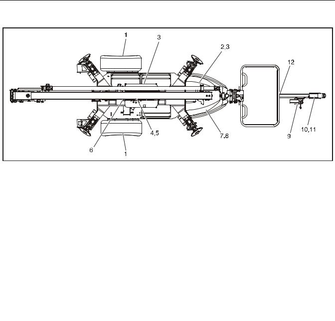
1. |
Wheel Bearings |
5. |
Swing Bearing Teeth |
9. |
Trailer Jack |
2. |
Hydraulic Oil |
6. |
Swing Drive |
10. |
Surge Brake |
3. |
Hydraulic Filter & Breather |
7. |
Engine |
11. |
Coupler & Hitch Ball |
4. |
Swing Bearing |
8. |
Fuel Tank |
12. |
Jockey Wheel Bearing |
Figure 1-1. Operator Maintenance & Lubrication Diagram
1.10OPERATOR MAINTENANCE & LUBRICATION
NOTE: Lubrication intervals are based on machine operation under normal conditions. For machines used in multi shift operations and/or exposed to hostile environments or conditions, lubrication frequencies must be increased accordingly.
|
Table 1-11.Lubrication Specifications |
|
|
|
|
KEY |
|
SPECIFICATIONS |
|
|
|
MPG |
|
Multipurpose Grease having a minimum dripping point of |
|
|
350 degrees F. Excellent water resistance and adhesive |
|
|
qualities; and being of extreme pressure type (Timken |
|
|
OK 40 pounds minimum). |
|
|
|
EPGL |
|
Extreme Pressure Gear Lube (oil) meeting API Service |
|
|
Classification GL-5 or Mil-Spec Mil-L-2105. |
|
|
|
HO |
|
Hydraulic Oil. API Service Classification GL-3, SAE |
|
|
10W-20, Viscosity Index 152, e.g. Mobilfluid 424. |
|
|
|
EO |
|
Engine (crankcase) Oil. Gas - API SF/SG class, MIL-L- |
|
|
2104. Diesel - API CC/CD class, MIL-L-2104B/MIL-L- |
|
|
2104C. |
|
|
|
OGL |
|
Open Gear Lubricant - Mobiltac 375 or equivalent. |
|
|
|
1. Wheel Bearings
Lube - MPG
Interval - every 12 months or 12,000 miles Comments - Refer to Section 3.5, Hubs, Drums, Wheel Bearings
1-4 |
– JLG Lift – |
3121200 |
SECTION 1 - SPECIFICATIONS
2. Hydraulic Oil
Lube Point(s) - Fill Cap Capacity - 4 gal. (15.1 L) Lube - HO
Interval - Check oil daily, change after, then every 1200 hours of operation.
3. Hydraulic Filter & Breather
4. Swing Bearing
Lube Point(s) - 1 Grease Fitting Capacity - As Required
Lube - MPG
Interval - Every month or 50 hours
Comments - Rotate the bearing back and forth
to ensure grease is distributed evenly the whole way around the bearing.
5.Swing Bearing Teeth
Lube Point(s) - Spray On Capacity - As Required Lube - OGL
Interval - Every month or 50 hours
Comments - More frequent lubrication intervals may be required.
6.Swing Drive
NOTE: The cap securing the filter must be torqued 154 to 170 ft.lbs. (209 to 230.5 Nm).
Interval - 100 hours
Comments - Change after the first 20 hours, then every 100 hours of operation.
Lube Point(s) - 2 Grease Fittings
Capacity - As Required
Lube - MPG
Interval - As Required
DO NOT OVERGREASE BEARINGS. OVERGREASING BEARINGS WILL RESULT IN BLOWING OUTER SEALS IN HOUSING.
3121200 |
– JLG Lift – |
1-5 |

SECTION 1 - SPECIFICATIONS
7. Engine
Capacity - See Engine Manual. Lube - EO, 10W30 API SJ
Interval - Check level daily; change per manufacturer’s engine manual.
Comments - Adjust final oil level by mark on dipstick 8. Fuel Tank
Capacity - 1.6 Gal. (6.0 L) Fuel - Gasoline
Interval - Check periodically during each shift 9. Trailer Jack
OIL
GREASE
Capacity - As necessary
Lube - MPG & EO
Interval - As necessary
10. Surge Brake
Lube Point(s) - Fill Cap
Capacity - No more than 1/2" (13 mm) from top of reservoir
Lube - DOT 3 or 4 Brake Fluid
Interval - Check before each tow. Flush the system yearly or when system is known to be contaminated
11. Coupler & Hitch Ball
Capacity - Coupler 2 Grease Fittings (CE Only); Hitch Ball
As necessary Lube - MPG
Interval - As necessary
12. Jockey Wheel Bearing (Drive and Set Option Only)
Lube Point(s) - 1 Grease Fittings
Capacity - As Required
Lube - MPG
Interval - As Required
1-6 |
– JLG Lift – |
3121200 |
SECTION 1 - SPECIFICATIONS
|
|
|
|
Values for Zinc Yellow Chromate Fasteners (Ref 4150707) |
|||||||||||||
|
|
|
|
|
|
SAE GRADE 5 BOLTS & GRADE 2 NUTS |
|
||||||||||
|
|
|
|
|
|
|
|
|
|
|
|
|
|
|
|
|
|
|
|
|
|
|
|
|
|
|
|
|
Torque |
|
Torque |
|
|||
|
|
|
Tensile |
|
Torque |
Torque |
|
(Loctite® 242TM or 271TM |
|
||||||||
Size |
TPI |
Bolt Dia |
Clamp Load |
|
|
TM |
or Vibra- |
||||||||||
Stress Area |
|
(Dry) |
Lubricated |
OR Vibra-TITE |
TM |
111 or |
(Loctite® 262 |
||||||||||
|
|
|
|
|
|
TITETM 131) |
|||||||||||
|
|
|
|
|
|
|
|
|
|
|
|
||||||
|
|
|
|
|
|
|
|
|
|
|
140) |
|
|
|
|
|
|
|
|
In |
Sq In |
LB |
IN-LB |
|
[N.m] |
IN-LB |
|
[N.m] |
IN-LB |
|
[N.m] |
IN-LB |
|
[N.m] |
|
4 |
40 |
0.1120 |
0.00604 |
380 |
8 |
|
0.9 |
6 |
|
0.7 |
|
|
|
|
|
|
|
|
48 |
0.1120 |
0.00661 |
420 |
9 |
|
1.0 |
7 |
|
0.8 |
|
|
|
|
|
|
|
6 |
32 |
0.1380 |
0.00909 |
580 |
16 |
|
1.8 |
12 |
|
1.4 |
|
|
|
|
|
|
|
|
40 |
0.1380 |
0.01015 |
610 |
18 |
|
2.0 |
13 |
|
1.5 |
|
|
|
|
|
|
|
8 |
32 |
0.1640 |
0.01400 |
900 |
30 |
|
3.4 |
22 |
|
2.5 |
|
|
|
|
|
|
|
|
36 |
0.1640 |
0.01474 |
940 |
31 |
|
3.5 |
23 |
|
2.6 |
|
|
|
|
|
|
|
10 |
24 |
0.1900 |
0.01750 |
1120 |
43 |
|
4.8 |
32 |
|
3.5 |
|
|
|
|
|
|
|
|
32 |
0.1900 |
0.02000 |
1285 |
49 |
|
5.5 |
36 |
|
4 |
|
|
|
|
|
|
|
1/4 |
20 |
0.2500 |
0.0318 |
2020 |
96 |
|
10.8 |
75 |
|
9 |
105 |
|
12 |
|
|
|
|
|
28 |
0.2500 |
0.0364 |
2320 |
120 |
|
13.5 |
86 |
|
10 |
135 |
|
15 |
|
|
|
|
|
|
In |
Sq In |
LB |
FT-LB |
|
[N.m] |
FT-LB |
|
[N.m] |
FT-LB |
|
[N.m] |
FT-LB |
|
[N.m] |
|
5/16 |
18 |
0.3125 |
0.0524 |
3340 |
17 |
|
23 |
13 |
|
18 |
19 |
|
26 |
16 |
|
22 |
|
|
24 |
0.3125 |
0.0580 |
3700 |
19 |
|
26 |
14 |
|
19 |
21 |
|
29 |
17 |
|
23 |
|
3/8 |
16 |
0.3750 |
0.0775 |
4940 |
30 |
|
41 |
23 |
|
31 |
35 |
|
48 |
28 |
|
38 |
|
|
24 |
0.3750 |
0.0878 |
5600 |
35 |
|
47 |
25 |
|
34 |
40 |
|
54 |
32 |
|
43 |
|
7/16 |
14 |
0.4375 |
0.1063 |
6800 |
50 |
|
68 |
35 |
|
47 |
55 |
|
75 |
45 |
|
61 |
|
|
20 |
0.4375 |
0.1187 |
7550 |
55 |
|
75 |
40 |
|
54 |
60 |
|
82 |
50 |
|
68 |
|
1/2 |
13 |
0.5000 |
0.1419 |
9050 |
75 |
|
102 |
55 |
|
75 |
85 |
|
116 |
68 |
|
92 |
|
|
20 |
0.5000 |
0.1599 |
10700 |
90 |
|
122 |
65 |
|
88 |
100 |
|
136 |
80 |
|
108 |
|
9/16 |
12 |
0.5625 |
0.1820 |
11600 |
110 |
|
149 |
80 |
|
108 |
120 |
|
163 |
98 |
|
133 |
|
|
18 |
0.5625 |
0.2030 |
12950 |
120 |
|
163 |
90 |
|
122 |
135 |
|
184 |
109 |
|
148 |
|
5/8 |
11 |
0.6250 |
0.2260 |
14400 |
150 |
|
203 |
110 |
|
149 |
165 |
|
224 |
135 |
|
183 |
|
|
18 |
0.6250 |
0.2560 |
16300 |
170 |
|
230 |
130 |
|
176 |
190 |
|
258 |
153 |
|
207 |
|
3/4 |
10 |
0.7500 |
0.3340 |
21300 |
260 |
|
353 |
200 |
|
271 |
285 |
|
388 |
240 |
|
325 |
|
|
16 |
0.7500 |
0.3730 |
23800 |
300 |
|
407 |
220 |
|
298 |
330 |
|
449 |
268 |
|
363 |
|
7/8 |
9 |
0.8750 |
0.4620 |
29400 |
430 |
|
583 |
320 |
|
434 |
475 |
|
646 |
386 |
|
523 |
|
|
14 |
0.8750 |
0.5090 |
32400 |
470 |
|
637 |
350 |
|
475 |
520 |
|
707 |
425 |
|
576 |
|
1 |
8 |
1.0000 |
0.6060 |
38600 |
640 |
|
868 |
480 |
|
651 |
675 |
|
918 |
579 |
|
785 |
|
|
12 |
1.0000 |
0.6630 |
42200 |
700 |
|
949 |
530 |
|
719 |
735 |
|
1000 |
633 |
|
858 |
|
1 1/8 |
7 |
1.1250 |
0.7630 |
42300 |
800 |
|
1085 |
600 |
|
813 |
840 |
|
1142 |
714 |
|
968 |
|
|
12 |
1.1250 |
0.8560 |
47500 |
880 |
|
1193 |
660 |
|
895 |
925 |
|
1258 |
802 |
|
1087 |
|
1 1/4 |
7 |
1.2500 |
0.9690 |
53800 |
1120 |
|
1518 |
840 |
|
1139 |
1175 |
|
1598 |
1009 |
|
1368 |
|
|
12 |
1.2500 |
1.0730 |
59600 |
1240 |
|
1681 |
920 |
|
1247 |
1300 |
|
1768 |
1118 |
|
1516 |
|
1 3/8 |
6 |
1.3750 |
1.1550 |
64100 |
1460 |
|
1979 |
1100 |
|
1491 |
1525 |
|
2074 |
1322 |
|
1792 |
|
|
12 |
1.3750 |
1.3150 |
73000 |
1680 |
|
2278 |
1260 |
|
1708 |
1750 |
|
2380 |
1506 |
|
2042 |
|
1 1/2 |
6 |
1.5000 |
1.4050 |
78000 |
1940 |
|
2630 |
1460 |
|
1979 |
2025 |
|
2754 |
1755 |
|
2379 |
|
|
12 |
1.5000 |
1.5800 |
87700 |
2200 |
|
2983 |
1640 |
|
2224 |
2300 |
|
3128 |
1974 |
|
2676 |
|
NOTES: |
1. THESE TORQUE VALUES DO NOT APPLY TO CADMIUM PLATED FASTENERS |
|
|
|
|
|
NO. 5000059 |
REV. J |
|||||||||
|
|
|
|
|
|
|
|
||||||||||
2.ALL TORQUE VALUES ARE STATIC TORQUE MEASURED PER STANDARD AUDIT METHODS TOLERANCE = ±10%
3.* ASSEMBLY USES HARDENED WASHER
|
REFERENCE JLG ANEROBIC THREAD LOCKING COMPOUND |
|||
JLG P/N |
Loctite® P/N |
|
ND Industries P/N |
Description |
|
|
|
|
|
0100011 |
242TM |
|
Vibra-TITETM 121 |
Medium Strength (Blue) |
0100019 |
271TM |
|
Vibra-TITETM 140 |
High Strength (Red) |
0100071 |
262TM |
|
Vibra-TITETM 131 |
Medium - High Strength (Red) |
Figure 1-2. Torque Chart (SAE Fasteners - Sheet 1 of 7)
3121200 |
– JLG Lift – |
1-7 |

SECTION 1 - SPECIFICATIONS
|
|
|
|
|
|
|
|
|
|
|
|
|
|
|
|
|
|
|
|
|
|
|
|
|
|
|
|
|
|
|
|
|
|
|
|
|
|
|
|
|
|
|
|
|
|
|
|
|
SAE GRADE 8 (HEX HD) BOLTS & GRADE 8 NUTS* |
||||||||||
|
|
|
|
|
|
|
|
|
|
|
|
|
|
|
|
|
|
|
|
|
Torque |
|
Torque |
|
Torque |
||||
|
|
|
Tensile |
|
|
|
(Loctite® 242TM or 271TM |
(Loctite® 262TM or Vibra- |
||||||
Size |
TPI |
Bolt Dia |
Stress Area |
Clamp Load |
(Dry or Loctite® 263) |
OR Vibra-TITETM 111 or |
TITETM 131) |
|||||||
|
|
|
|
|
|
K= 0.20 |
140) |
|
K=.18 |
K=0.15 |
||||
|
|
|
|
|
|
|
|
|
|
|||||
|
|
In |
Sq In |
|
LB |
IN-LB |
|
[N.m] |
IN-LB |
|
[N.m] |
IN-LB |
|
[N.m] |
4 |
40 |
0.1120 |
0.00604 |
|
|
|
|
|
|
|
|
|
|
|
|
48 |
0.1120 |
0.00661 |
|
|
|
|
|
|
|
|
|
|
|
6 |
32 |
0.1380 |
0.00909 |
|
|
|
|
|
|
|
|
|
|
|
|
40 |
0.1380 |
0.01015 |
|
|
|
|
|
|
|
|
|
|
|
8 |
32 |
0.1640 |
0.01400 |
|
|
|
|
|
|
|
|
|
|
|
|
36 |
0.1640 |
0.01474 |
1320 |
43 |
|
5 |
|
|
|
|
|
|
|
10 |
24 |
0.1900 |
0.01750 |
1580 |
60 |
|
7 |
|
|
|
|
|
|
|
|
32 |
0.1900 |
0.02000 |
1800 |
68 |
|
8 |
|
|
|
|
|
|
|
1/4 |
20 |
0.2500 |
0.0318 |
2860 |
143 |
|
16 |
129 |
|
15 |
|
|
|
|
|
28 |
0.2500 |
0.0364 |
3280 |
164 |
|
19 |
148 |
|
17 |
|
|
|
|
|
|
In |
Sq In |
LB |
FT-LB |
|
[N.m] |
FT-LB |
|
[N.m] |
FT-LB |
|
[N.m |
|
5/16 |
18 |
0.3125 |
0.0524 |
4720 |
25 |
|
35 |
20 |
|
25 |
20 |
|
25 |
|
|
24 |
0.3125 |
0.0580 |
5220 |
25 |
|
35 |
25 |
|
35 |
20 |
|
25 |
|
3/8 |
16 |
0.3750 |
0.0775 |
7000 |
45 |
|
60 |
40 |
|
55 |
35 |
|
50 |
|
|
24 |
0.3750 |
0.0878 |
7900 |
50 |
|
70 |
45 |
|
60 |
35 |
|
50 |
|
7/16 |
14 |
0.4375 |
0.1063 |
9550 |
70 |
|
95 |
65 |
|
90 |
50 |
|
70 |
|
|
20 |
0.4375 |
0.1187 |
10700 |
80 |
|
110 |
70 |
|
95 |
60 |
|
80 |
|
1/2 |
13 |
0.5000 |
0.1419 |
12750 |
105 |
|
145 |
95 |
|
130 |
80 |
|
110 |
|
|
20 |
0.5000 |
0.1599 |
14400 |
120 |
|
165 |
110 |
|
150 |
90 |
|
120 |
|
9/16 |
12 |
0.5625 |
0.1820 |
16400 |
155 |
|
210 |
140 |
|
190 |
115 |
|
155 |
|
|
18 |
0.5625 |
0.2030 |
18250 |
170 |
|
230 |
155 |
|
210 |
130 |
|
175 |
|
5/8 |
11 |
0.6250 |
0.2260 |
20350 |
210 |
|
285 |
190 |
|
260 |
160 |
|
220 |
|
|
18 |
0.6250 |
0.2560 |
23000 |
240 |
|
325 |
215 |
|
290 |
180 |
|
245 |
|
3/4 |
10 |
0.7500 |
0.3340 |
30100 |
375 |
|
510 |
340 |
|
460 |
280 |
|
380 |
|
|
16 |
0.7500 |
0.3730 |
33600 |
420 |
|
570 |
380 |
|
515 |
315 |
|
430 |
|
7/8 |
9 |
0.8750 |
0.4620 |
41600 |
605 |
|
825 |
545 |
|
740 |
455 |
|
620 |
|
|
14 |
0.8750 |
0.5090 |
45800 |
670 |
|
910 |
600 |
|
815 |
500 |
|
680 |
|
1 |
8 |
1.0000 |
0.6060 |
51500 |
860 |
|
1170 |
770 |
|
1045 |
645 |
|
875 |
|
|
12 |
1.0000 |
0.6630 |
59700 |
995 |
|
1355 |
895 |
|
1215 |
745 |
|
1015 |
|
1 1/8 |
7 |
1.1250 |
0.7630 |
68700 |
1290 |
|
1755 |
1160 |
|
1580 |
965 |
|
1310 |
|
|
12 |
1.1250 |
0.8560 |
77000 |
1445 |
|
1965 |
1300 |
|
1770 |
1085 |
|
1475 |
|
1 1/4 |
7 |
1.2500 |
0.9690 |
87200 |
1815 |
|
2470 |
1635 |
|
2225 |
1365 |
|
1855 |
|
|
12 |
1.2500 |
1.0730 |
96600 |
2015 |
|
2740 |
1810 |
|
2460 |
1510 |
|
2055 |
|
1 3/8 |
6 |
1.3750 |
1.1550 |
104000 |
2385 |
|
3245 |
2145 |
|
2915 |
1785 |
|
2430 |
|
|
12 |
1.3750 |
1.3150 |
118100 |
2705 |
|
3680 |
2435 |
|
3310 |
2030 |
|
2760 |
|
1 1/2 |
6 |
1.5000 |
1.4050 |
126500 |
3165 |
|
4305 |
2845 |
|
3870 |
2370 |
|
3225 |
|
|
12 |
1.5000 |
1.5800 |
142200 |
3555 |
|
4835 |
3200 |
|
4350 |
2665 |
|
3625 |
|
NOTES: |
1. THESE TORQUE VALUES DO NOT APPLY TO CADMIUM PLATED FASTENERS |
|
NO. 5000059 |
REV. J |
||||||||||
|
|
|
|
|||||||||||
2.ALL TORQUE VALUES ARE STATIC TORQUE MEASURED PER STANDARD AUDIT METHODS TOLERANCE = ±10%
3.* ASSEMBLY USES HARDENED WASHER
Figure 1-3. Torque Chart (SAE Fasteners - Sheet 2 of 7)
1-8 |
– JLG Lift – |
3121200 |

SECTION 1 - SPECIFICATIONS
|
|
|
|
|
SOCKET HEAD CAP SCREWS |
|
|
||||||
|
|
|
|
|
|
|
|
||||||
|
|
|
|
|
Magni Coating (Ref 4150701)* |
|
|
||||||
|
|
|
|
|
|
|
|
|
|
|
|
|
|
|
|
|
|
|
|
|
Torque |
|
Torque |
|
|
||
|
|
|
|
|
|
|
(Loctite® 242TM or 271TM |
|
|
||||
Size |
TPI |
Bolt Dia |
Tensile |
Clamp Load |
Torque |
(Loctite® 262TM |
|||||||
Stress Area |
See Note 4 |
(Dry) |
K = .17 |
OR Vibra-TITETM 111 or |
or Vibra-TITE |
TM |
131) |
||||||
|
|
|
140 OR Precoat 85® |
|
|||||||||
|
|
|
|
|
|
|
K=0.15 |
|
|||||
|
|
|
|
|
|
|
K=0.16 |
|
|
|
|
|
|
|
|
In |
Sq In |
LB |
IN-LB |
[N.m] |
IN-LB |
|
[N.m] |
IN-LB |
|
[N.m] |
|
4 |
40 |
0.1120 |
0.00604 |
|
|
|
|
|
|
|
|
|
|
|
48 |
0.1120 |
0.00661 |
|
|
|
|
|
|
|
|
|
|
6 |
32 |
0.1380 |
0.00909 |
|
|
|
|
|
|
|
|
|
|
|
40 |
0.1380 |
0.01015 |
|
|
|
|
|
|
|
|
|
|
8 |
32 |
0.1640 |
0.01400 |
|
|
|
|
|
|
|
|
|
|
|
36 |
0.1640 |
0.01474 |
|
|
|
|
|
|
|
|
|
|
10 |
24 |
0.1900 |
0.01750 |
|
|
|
|
|
|
|
|
|
|
|
32 |
0.1900 |
0.02000 |
|
|
|
|
|
|
|
|
|
|
1/4 |
20 |
0.2500 |
0.0318 |
2860 |
122 |
14 |
114 |
|
13 |
|
|
|
|
|
28 |
0.2500 |
0.0364 |
3280 |
139 |
16 |
131 |
|
15 |
|
|
|
|
|
|
In |
Sq In |
LB |
FT-LB |
[N.m] |
FT-LB |
|
[N.m] |
FT-LB |
|
[N.m] |
|
5/16 |
18 |
0.3125 |
0.0524 |
4720 |
20 |
25 |
20 |
|
25 |
20 |
|
25 |
|
|
24 |
0.3125 |
0.0580 |
5220 |
25 |
35 |
20 |
|
25 |
20 |
|
25 |
|
3/8 |
16 |
0.3750 |
0.0775 |
7000 |
35 |
50 |
35 |
|
50 |
35 |
|
50 |
|
|
24 |
0.3750 |
0.0878 |
7900 |
40 |
55 |
40 |
|
55 |
35 |
|
50 |
|
7/16 |
14 |
0.4375 |
0.1063 |
9550 |
60 |
80 |
55 |
|
75 |
50 |
|
70 |
|
|
20 |
0.4375 |
0.1187 |
10700 |
65 |
90 |
60 |
|
80 |
60 |
|
80 |
|
1/2 |
13 |
0.5000 |
0.1419 |
12750 |
90 |
120 |
85 |
|
115 |
80 |
|
110 |
|
|
20 |
0.5000 |
0.1599 |
14400 |
100 |
135 |
95 |
|
130 |
90 |
|
120 |
|
9/16 |
12 |
0.5625 |
0.1820 |
16400 |
130 |
175 |
125 |
|
170 |
115 |
|
155 |
|
|
18 |
0.5625 |
0.2030 |
18250 |
145 |
195 |
135 |
|
185 |
130 |
|
175 |
|
5/8 |
11 |
0.6250 |
0.2260 |
20350 |
180 |
245 |
170 |
|
230 |
160 |
|
220 |
|
|
18 |
0.6250 |
0.2560 |
23000 |
205 |
280 |
190 |
|
260 |
180 |
|
245 |
|
3/4 |
10 |
0.7500 |
0.3340 |
30100 |
320 |
435 |
300 |
|
410 |
280 |
|
380 |
|
|
16 |
0.7500 |
0.3730 |
33600 |
355 |
485 |
335 |
|
455 |
315 |
|
430 |
|
7/8 |
9 |
0.8750 |
0.4620 |
41600 |
515 |
700 |
485 |
|
660 |
455 |
|
620 |
|
|
14 |
0.8750 |
0.5090 |
45800 |
570 |
775 |
535 |
|
730 |
500 |
|
680 |
|
1 |
8 |
1.0000 |
0.6060 |
51500 |
730 |
995 |
685 |
|
930 |
645 |
|
875 |
|
|
12 |
1.0000 |
0.6630 |
59700 |
845 |
1150 |
795 |
|
1080 |
745 |
|
1015 |
|
1 1/8 |
7 |
1.1250 |
0.7630 |
68700 |
1095 |
1490 |
1030 |
|
1400 |
965 |
|
1310 |
|
|
12 |
1.1250 |
0.8560 |
77000 |
1225 |
1665 |
1155 |
|
1570 |
1085 |
|
1475 |
|
1 1/4 |
7 |
1.2500 |
0.9690 |
87200 |
1545 |
2100 |
1455 |
|
1980 |
1365 |
|
1855 |
|
|
12 |
1.2500 |
1.0730 |
96600 |
1710 |
2325 |
1610 |
|
2190 |
1510 |
|
2055 |
|
1 3/8 |
6 |
1.3750 |
1.1550 |
104000 |
2025 |
2755 |
1905 |
|
2590 |
1785 |
|
2430 |
|
|
12 |
1.3750 |
1.3150 |
118100 |
2300 |
3130 |
2165 |
|
2945 |
2030 |
|
2760 |
|
1 1/2 |
6 |
1.5000 |
1.4050 |
126500 |
2690 |
3660 |
2530 |
|
3440 |
2370 |
|
3225 |
|
|
12 |
1.5000 |
1.5800 |
142200 |
3020 |
4105 |
2845 |
|
3870 |
2665 |
|
3625 |
|
NOTES: 1. THESE TORQUE VALUES DO NOT APPLY TO CADMIUM PLATED FASTENERS
2. ALL TORQUE VALUES ARE STATIC TORQUE MEASURED PER STANDARD AUDIT METHODS TOLERANCE = ±10% *3. ASSEMBLY USES HARDENED WASHER OR FASTENER IS PLACED AGAINST PLATED STEEL OR RAW ALUMINUM
4.CLAMP LOAD LISTED FOR SHCS IS SAME AS GRADE 8 OR CLASS 10.9 AND DOES NOT REPRESENT FULL STRENGTH
CAPABILITY OF SHCS. IF HIGHER LOAD IS REQUIRED, ADDITIONAL TESTING IS REQUIRED.
Figure 1-4. Torque Chart (SAE Fasteners - Sheet 3 of 7)
3121200 |
– JLG Lift – |
1-9 |

SECTION 1 - SPECIFICATIONS
|
|
|
|
|
SOCKET HEAD CAP SCREWS |
|
|
|||||||
|
|
|
|
Zinc Yellow Chromate Fasteners (Ref 4150707)* |
|
|||||||||
|
|
|
|
|
|
|
|
|
|
|
|
|
|
|
|
|
|
|
|
|
|
|
Torque |
|
Torque |
|
|
||
|
|
|
|
|
Torque |
|
(Loctite® 242TM or 271TM |
|
|
|||||
Size |
TPI |
Bolt Dia |
Tensile |
Clamp Load |
|
(Loctite® 262TM |
||||||||
Stress Area |
See Note 4 |
(Dry) |
|
OR Vibra-TITETM 111 or |
or Vibra-TITE |
TM |
131) |
|||||||
|
|
|
K = .20 |
140 OR Precoat 85® |
|
|||||||||
|
|
|
|
|
K=0.15 |
|
||||||||
|
|
|
|
|
|
|
|
K=0.18 |
|
|||||
|
|
|
|
|
|
|
|
|
|
|
|
|||
|
|
In |
Sq In |
LB |
IN-LB |
|
[N.m] |
IN-LB |
|
[N.m] |
IN-LB |
|
[N.m] |
|
4 |
40 |
0.1120 |
0.00604 |
|
|
|
|
|
|
|
|
|
|
|
|
48 |
0.1120 |
0.00661 |
|
|
|
|
|
|
|
|
|
|
|
6 |
32 |
0.1380 |
0.00909 |
|
|
|
|
|
|
|
|
|
|
|
|
40 |
0.1380 |
0.01015 |
|
|
|
|
|
|
|
|
|
|
|
8 |
32 |
0.1640 |
0.01400 |
|
|
|
|
|
|
|
|
|
|
|
|
36 |
0.1640 |
0.01474 |
|
|
|
|
|
|
|
|
|
|
|
10 |
24 |
0.1900 |
0.01750 |
|
|
|
|
|
|
|
|
|
|
|
|
32 |
0.1900 |
0.02000 |
|
|
|
|
|
|
|
|
|
|
|
1/4 |
20 |
0.2500 |
0.0318 |
2860 |
143 |
|
16 |
129 |
|
15 |
|
|
|
|
|
28 |
0.2500 |
0.0364 |
3280 |
164 |
|
19 |
148 |
|
17 |
|
|
|
|
|
|
In |
Sq In |
LB |
FT-LB |
|
[N.m] |
FT-LB |
|
[N.m] |
FT-LB |
|
[N.m] |
|
5/16 |
18 |
0.3125 |
0.0524 |
4720 |
25 |
|
35 |
20 |
|
25 |
20 |
|
25 |
|
|
24 |
0.3125 |
0.0580 |
5220 |
25 |
|
35 |
25 |
|
35 |
20 |
|
25 |
|
3/8 |
16 |
0.3750 |
0.0775 |
7000 |
45 |
|
60 |
40 |
|
55 |
35 |
|
50 |
|
|
24 |
0.3750 |
0.0878 |
7900 |
50 |
|
70 |
45 |
|
60 |
35 |
|
50 |
|
7/16 |
14 |
0.4375 |
0.1063 |
9550 |
70 |
|
95 |
65 |
|
90 |
50 |
|
70 |
|
|
20 |
0.4375 |
0.1187 |
10700 |
80 |
|
110 |
70 |
|
95 |
60 |
|
80 |
|
1/2 |
13 |
0.5000 |
0.1419 |
12750 |
105 |
|
145 |
95 |
|
130 |
80 |
|
110 |
|
|
20 |
0.5000 |
0.1599 |
14400 |
120 |
|
165 |
110 |
|
150 |
90 |
|
120 |
|
9/16 |
12 |
0.5625 |
0.1820 |
16400 |
155 |
|
210 |
140 |
|
190 |
115 |
|
155 |
|
|
18 |
0.5625 |
0.2030 |
18250 |
170 |
|
230 |
155 |
|
210 |
130 |
|
175 |
|
5/8 |
11 |
0.6250 |
0.2260 |
20350 |
210 |
|
285 |
190 |
|
260 |
160 |
|
220 |
|
|
18 |
0.6250 |
0.2560 |
23000 |
240 |
|
325 |
215 |
|
290 |
180 |
|
245 |
|
3/4 |
10 |
0.7500 |
0.3340 |
30100 |
375 |
|
510 |
340 |
|
460 |
280 |
|
380 |
|
|
16 |
0.7500 |
0.3730 |
33600 |
420 |
|
570 |
380 |
|
515 |
315 |
|
430 |
|
7/8 |
9 |
0.8750 |
0.4620 |
41600 |
605 |
|
825 |
545 |
|
740 |
455 |
|
620 |
|
|
14 |
0.8750 |
0.5090 |
45800 |
670 |
|
910 |
600 |
|
815 |
500 |
|
680 |
|
1 |
8 |
1.0000 |
0.6060 |
51500 |
860 |
|
1170 |
775 |
|
1055 |
645 |
|
875 |
|
|
12 |
1.0000 |
0.6630 |
59700 |
995 |
|
1355 |
895 |
|
1215 |
745 |
|
1015 |
|
1 1/8 |
7 |
1.1250 |
0.7630 |
68700 |
1290 |
|
1755 |
1160 |
|
1580 |
965 |
|
1310 |
|
|
12 |
1.1250 |
0.8560 |
77000 |
1445 |
|
1965 |
1300 |
|
1770 |
1085 |
|
1475 |
|
1 1/4 |
7 |
1.2500 |
0.9690 |
87200 |
1815 |
|
2470 |
1635 |
|
2225 |
1365 |
|
1855 |
|
|
12 |
1.2500 |
1.0730 |
96600 |
2015 |
|
2740 |
1810 |
|
2460 |
1510 |
|
2055 |
|
1 3/8 |
6 |
1.3750 |
1.1550 |
104000 |
2385 |
|
3245 |
2145 |
|
2915 |
1785 |
|
2430 |
|
|
12 |
1.3750 |
1.3150 |
118100 |
2705 |
|
3680 |
2435 |
|
3310 |
2030 |
|
2760 |
|
1 1/2 |
6 |
1.5000 |
1.4050 |
126500 |
3165 |
|
4305 |
2845 |
|
3870 |
2370 |
|
3225 |
|
|
12 |
1.5000 |
1.5800 |
142200 |
3555 |
|
4835 |
3200 |
|
4350 |
2665 |
|
3625 |
|
NOTES: 1. THESE TORQUE VALUES DO NOT APPLY TO CADMIUM PLATED FASTENERS
2. ALL TORQUE VALUES ARE STATIC TORQUE MEASURED PER STANDARD AUDIT METHODS TOLERANCE = ±10% *3. ASSEMBLY USES HARDENED WASHER OR FASTENER IS PLACED AGAINST PLATED STEEL OR RAW ALUMINUM
4.CLAMP LOAD LISTED FOR SHCS IS SAME AS GRADE 8 OR CLASS 10.9 AND DOES NOT REPRESENT FULL STRENGTH
CAPABILITY OF SHCS. IF HIGHER LOAD IS REQUIRED, ADDITIONAL TESTING IS REQUIRED.
Figure 1-5. Torque Chart (SAE Fasteners - Sheet 4 of 7)
1-10 |
– JLG Lift – |
3121200 |

SECTION 1 - SPECIFICATIONS
|
|
|
|
|
|
|
|
|
|
|
|
|
|
|
CLASS 8.8 METRIC BOLTS |
|
|||
|
|
|
|
|
CLASS 8 METRIC NUTS |
|
|||
|
|
|
|
|
|
|
|
|
|
|
|
|
|
|
|
|
|
Torque |
Torque |
|
|
Tensile |
|
|
Torque |
|
(Loctite® |
||
Size |
PITCH |
Clamp |
Torque |
(Loctite® 262TM |
242TM or 271TM |
||||
Stress |
Load |
(Dry or Loctite® |
(Lub) |
OR Vibra- |
OR Vibra- |
||||
|
|
Area |
TM |
||||||
|
|
|
|
263 ) |
|
|
TITETM 131) |
TITETM 111 or |
|
|
|
|
|
|
|
|
|||
|
|
|
|
|
|
|
|
|
140) |
|
|
Sq mm |
|
KN |
[N.m] |
[N.m] |
[N.m] |
[N.m] |
|
|
|
|
|
|
|
|
|
|
|
3 |
0.5 |
5.03 |
2.19 |
1.3 |
|
1.0 |
1.2 |
1.4 |
|
3.5 |
0.6 |
6.78 |
2.95 |
2.1 |
|
1.6 |
1.9 |
2.3 |
|
4 |
0.7 |
8.78 |
3.82 |
3.1 |
|
2.3 |
2.8 |
3.4 |
|
5 |
0.8 |
14.20 |
6.18 |
6.2 |
|
4.6 |
5.6 |
6.8 |
|
6 |
1 |
20.10 |
8.74 |
11 |
|
7.9 |
9.4 |
12 |
|
7 |
1 |
28.90 |
12.6 |
18 |
|
13 |
16 |
19 |
|
8 |
1.25 |
36.60 |
15.9 |
26 |
|
19 |
23 |
28 |
|
10 |
1.5 |
58.00 |
25.2 |
50 |
|
38 |
45 |
55 |
|
12 |
1.75 |
84.30 |
36.7 |
88 |
|
66 |
79 |
97 |
|
14 |
2 |
115 |
50.0 |
140 |
|
105 |
126 |
154 |
|
16 |
2 |
157 |
68.3 |
219 |
|
164 |
197 |
241 |
|
18 |
2.5 |
192 |
83.5 |
301 |
|
226 |
271 |
331 |
|
20 |
2.5 |
245 |
106.5 |
426 |
|
320 |
383 |
469 |
|
22 |
2.5 |
303 |
132.0 |
581 |
|
436 |
523 |
639 |
|
24 |
3 |
353 |
153.5 |
737 |
|
553 |
663 |
811 |
|
27 |
3 |
459 |
199.5 |
1080 |
|
810 |
970 |
1130 |
|
30 |
3.5 |
561 |
244.0 |
1460 |
|
1100 |
1320 |
1530 |
|
33 |
3.5 |
694 |
302.0 |
1990 |
|
1490 |
1790 |
2090 |
|
36 |
4 |
817 |
355.5 |
2560 |
|
1920 |
2300 |
2690 |
|
42 |
4.5 |
1120 |
487.0 |
4090 |
|
3070 |
3680 |
4290 |
|
|
|
|
|
|
|
|
|
NO. 5000059 REV. J |
|
NOTES: 1. THESE TORQUE VALUES DO NOT APPLY TO CADMIUM PLATED FASTENERS
2.ALL TORQUE VALUES ARE STATIC TORQUE MEASURED PER STANDARD AUDIT METHODS TOLERANCE = ±10%
*3. ASSEMBLY USES HARDENED WASHER OR FASTENER IS PLACED AGAINST PLATED STEEL OR RAW ALUMINUM
4.CLAMP LOAD LISTED FOR SHCS IS SAME AS GRADE 8 OR CLASS 10.9 AND DOES NOT REPRESENT FULL STRENGTH CAPABILITY OF SHCS. IF HIGHER LOAD IS REQUIRED, ADDITIONAL TESTING IS REQUIRED.
Figure 1-6. Torque Chart (METRIC Fasteners - Sheet 5 of 7)
3121200 |
– JLG Lift – |
1-11 |

SECTION 1 - SPECIFICATIONS
|
|
|
|
|
|
|
|
|
|
|
|
|
|
CLASS 10.9 METRIC BOLTS |
|||
|
|
|
|
|
CLASS 10 METRIC NUTS |
|||
|
|
|
CLASS 12.9 SOCKET HEAD CAP SCREWS M3 - M5* |
|||||
|
|
|
|
|
|
|
|
|
|
|
|
|
|
|
|
Torque |
Torque |
|
|
Tensile |
|
|
Torque |
(Lub OR Loctite® |
||
Size |
PITCH |
Clamp |
(Dry or Loctite® |
242TM or 271TM OR |
(Loctite® 262TM OR |
|||
Stress |
Load |
263TM) |
Vibra-TITETM 111 or |
Vibra-TITETM 131) |
||||
|
|
Area |
||||||
|
|
|
|
K = 0.20 |
140) |
K=0.15 |
||
|
|
|
|
|
||||
|
|
|
|
|
|
|
K= 0.18 |
|
|
|
Sq mm |
|
KN |
[N.m] |
[N.m] |
[N.m] |
|
|
|
|
|
|
|
|
|
|
3 |
0.5 |
5.03 |
3.13 |
|
|
|
|
|
3.5 |
0.6 |
6.78 |
4.22 |
|
|
|
|
|
4 |
0.7 |
8.78 |
5.47 |
|
|
|
|
|
5 |
0.8 |
14.20 |
8.85 |
|
|
|
|
|
6 |
1 |
20.10 |
12.5 |
|
|
|
|
|
7 |
1 |
28.90 |
18.0 |
25.2 |
|
22.7 |
18.9 |
|
8 |
1.25 |
36.60 |
22.8 |
36.5 |
|
32.8 |
27.4 |
|
10 |
1.5 |
58.00 |
36.1 |
70 |
|
65 |
55 |
|
12 |
1.75 |
84.30 |
52.5 |
125 |
|
115 |
95 |
|
14 |
2 |
115 |
71.6 |
200 |
|
180 |
150 |
|
16 |
2 |
157 |
97.8 |
315 |
|
280 |
235 |
|
18 |
2.5 |
192 |
119.5 |
430 |
|
385 |
325 |
|
20 |
2.5 |
245 |
152.5 |
610 |
|
550 |
460 |
|
22 |
2.5 |
303 |
189.0 |
830 |
|
750 |
625 |
|
24 |
3 |
353 |
222.0 |
1065 |
|
960 |
800 |
|
27 |
3 |
459 |
286.0 |
1545 |
|
1390 |
1160 |
|
30 |
3.5 |
561 |
349.5 |
2095 |
|
1885 |
1575 |
|
33 |
3.5 |
694 |
432.5 |
2855 |
|
2570 |
2140 |
|
36 |
4 |
817 |
509.0 |
3665 |
|
3300 |
2750 |
|
42 |
4.5 |
1120 |
698.0 |
5865 |
|
5275 |
4395 |
|
|
|
|
|
|
|
|
NO. 5000059 REV. J |
|
NOTES: 1. THESE TORQUE VALUES DO NOT APPLY TO CADMIUM PLATED FASTENERS
2.ALL TORQUE VALUES ARE STATIC TORQUE MEASURED PER STANDARD AUDIT METHODS TOLERANCE = ±10%
*3. ASSEMBLY USES HARDENED WASHER OR FASTENER IS PLACED AGAINST PLATED STEEL OR RAW ALUMINUM
4.CLAMP LOAD LISTED FOR SHCS IS SAME AS GRADE 8 OR CLASS 10.9 AND DOES NOT REPRESENT FULL STRENGTH CAPABILITY OF SHCS. IF HIGHER LOAD IS REQUIRED,
ADDITIONAL TESTING IS REQUIRED.
Figure 1-7. Torque Chart (METRIC Fasteners - Sheet 6 of 7)
1-12 |
– JLG Lift – |
3121200 |
SECTION 1 - SPECIFICATIONS
Magni Coating (Ref 4150701)*
CLASS 12.9 SOCKET HEAD CAP SCREWS
M6 AND ABOVE*
|
|
|
|
|
Torque |
Torque |
|
|
|
|
|
Torque |
(Lub OR Loctite® |
|
|
|
|
Tensile |
|
(Loctite® 262TM |
|||
Size |
PITCH |
Clamp Load |
(Dry or Loctite® |
242TM or 271TM |
|||
Stress |
See Note 4 |
263TM) |
OR Vibra-TITETM |
OR Vibra-TITE |
TM |
||
|
|
Area |
|
||||
|
|
|
K = .17 |
111 or 140) |
131) |
|
|
|
|
|
|
K = .15 |
|
||
|
|
|
|
|
K = .16 |
|
|
|
|
|
|
|
|
|
|
|
|
Sq mm |
kN |
[N.m] |
[N.m] |
[N.m] |
|
|
|
|
|
|
|
|
|
3 |
0.5 |
5.03 |
|
|
|
|
|
3.5 |
0.6 |
6.78 |
|
|
|
|
|
4 |
0.7 |
8.78 |
|
|
|
|
|
5 |
0.8 |
14.20 |
|
|
|
|
|
6 |
1 |
20.10 |
12.5 |
13 |
12 |
11 |
|
7 |
1 |
28.90 |
18.0 |
21 |
20 |
19 |
|
8 |
1.25 |
36.60 |
22.8 |
31 |
29 |
27 |
|
10 |
1.5 |
58.00 |
36.1 |
61 |
58 |
54 |
|
12 |
1.75 |
84.30 |
52.5 |
105 |
100 |
95 |
|
14 |
2 |
115 |
71.6 |
170 |
160 |
150 |
|
16 |
2 |
157 |
97.8 |
265 |
250 |
235 |
|
18 |
2.5 |
192 |
119.5 |
365 |
345 |
325 |
|
20 |
2.5 |
245 |
152.5 |
520 |
490 |
460 |
|
22 |
2.5 |
303 |
189.0 |
705 |
665 |
625 |
|
24 |
3 |
353 |
220.0 |
900 |
845 |
790 |
|
27 |
3 |
459 |
286.0 |
1315 |
1235 |
1160 |
|
30 |
3.5 |
561 |
349.5 |
1780 |
1680 |
1575 |
|
33 |
3.5 |
694 |
432.5 |
2425 |
2285 |
2140 |
|
36 |
4 |
817 |
509.0 |
3115 |
2930 |
2750 |
|
42 |
4.5 |
1120 |
698.0 |
4985 |
4690 |
4395 |
|
|
|
|
|
|
NO. 5000059 REV. J |
||
NOTES: 1. THESE TORQUE VALUES DO NOT APPLY TO CADMIUM PLATED FASTENERS
2.ALL TORQUE VALUES ARE STATIC TORQUE MEASURED PER STANDARD AUDIT METHODS TOLERANCE = ±10%
*3. ASSEMBLY USES HARDENED WASHER OR FASTENER IS PLACED AGAINST PLATED STEEL OR RAW ALUMINUM
4.CLAMP LOAD LISTED FOR SHCS IS SAME AS GRADE 8 OR CLASS 10.9 AND DOES NOT REPRESENT FULL STRENGTH CAPABILITY OF SHCS. IF HIGHER LOAD IS REQUIRED,
ADDITIONAL TESTING IS REQUIRED.
Figure 1-8. Torque Chart (METRIC Fasteners - Sheet 7 of 7)
3121200 |
– JLG Lift – |
1-13 |

SECTION 1 - SPECIFICATIONS
 NOTES:
1-14 |
– JLG Lift – |
3121200 |

SECTION 2 - GENERAL
SECTION 2. GENERAL
2.1MACHINE PREPARATION, INSPECTION, AND MAINTENANCE
General
This section provides the necessary information needed by those personnel that are responsible to place the machine in operation readiness and maintain its safe operating condition. For maximum service life and safe operation, ensure that all the necessary inspections and maintenance have been completed before placing the machine into service.
Preparation, Inspection, and Maintenance
It is important to establish and conform to a comprehensive inspection and preventive maintenance program. The following table outlines the periodic machine inspections and maintenance recommended by JLG Industries, Inc. Consult your national, regional, or local regulations for further requirements for aerial work platforms. The frequency of inspections and maintenance must be increased as environment, severity and frequency of usage requires.
Pre-Start Inspection
It is the User’s or Operator’s primary responsibility to perform a Pre-Start Inspection of the machine prior to use daily or at each change of operator. Reference the Operator’s and Safety Manual for completion procedures for the Pre-Start Inspection. The Operator and Safety Manual must be read in its entirety and understood prior to performing the Pre-Start Inspection.
Pre-Delivery Inspection and Frequent Inspection
The Pre-Delivery Inspection and Frequent Inspection shall be performed by a qualified JLG equipment mechanic. JLG Industries, Inc. recognizes a qualified JLG equipment mechanic as a person who, by possession of a recognized degree, certificate, extensive knowledge, training, or experience, has successfully demonstrated the ability and proficiency to service, repair, and maintain the subject JLG product model.
The Pre-Delivery Inspection and Frequent Inspection procedures are performed in the same manner, but at different times. The Pre-Delivery Inspection shall be performed prior to each sale, lease, or rental delivery. The Frequent Inspection shall be accomplished for each machine in service for 3 months or 150 hours (whichever comes first); out of service for a period of more than 3 months; or when purchased used. The frequency of this inspection must be increased as environment, severity and frequency of usage requires.
Reference the JLG Pre-Delivery and Frequent Inspection Form and the Inspection and Preventative Maintenance Schedule for items requiring inspection during the performance of these inspections. Reference the appropriate areas of this manual for servicing and maintenance procedures.
Annual Machine Inspection
The Annual Machine Inspection must be performed by a Factory-Certified Service Technician on an annual basis, no later than thirteen (13) months from the date of the prior Annual Machine Inspection. JLG Industries, Inc. recognizes a Factory-Certified Service Technician as a person who has successfully completed the JLG Service Training School for the subject JLG product model. Reference the machine Service and Maintenance Manual and appropriate JLG inspection form for performance of this inspection.
Reference the JLG Annual Machine Inspection Form and the Inspection and Preventative Maintenance Schedule for items requiring inspection during the performance of this inspection. Reference the appropriate areas of this manual for servicing and maintenance procedures.
For the purpose of receiving safety-related bulletins, it is important that JLG Industries, Inc. has updated ownership information for each machine. When performing each Annual Machine Inspection, notify JLG Industries, Inc. of the current machine ownership.
Preventative Maintenance
In conjunction with the specified inspections, maintenance shall be performed by a qualified JLG equipment mechanic. JLG Industries, Inc. recognizes a qualified JLG equipment mechanic as a person who, by possession of a recognized degree, certificate, extensive knowledge, training, or experience, has successfully demonstrated the ability and proficiency to service, repair, and maintain the subject JLG product model.
Reference the Preventative Maintenance Schedule and the appropriate areas of this manual for servicing and maintenance procedures. The frequency of service and maintenance must be increased as environment, severity and frequency of usage requires.
3121200 |
– JLG Lift – |
2-1 |

SECTION 2 - GENERAL
Table 2-1. Inspection and Maintenance
Type |
Frequency |
Primary |
Service |
Reference |
|
Responsibility |
Qualification |
||||
|
|
|
|||
|
|
|
|
|
|
Pre-Start Inspection |
Prior to use each day; or |
User or Operator |
User or Operator |
Operator and Safety Manual |
|
|
At each Operator change. |
|
|
|
|
|
|
|
|
|
|
Pre-Delivery |
Prior to each sale, lease, or |
Owner, Dealer, or User |
Qualified JLG |
Service and Maintenance |
|
Inspection |
rental delivery. |
|
Mechanic |
Manual and applicable JLG |
|
|
|
|
|
inspection form. |
|
|
|
|
|
|
|
Frequent Inspection |
In service for 3 months or 150 hours, which- |
Owner, Dealer, or User |
Qualified JLG |
Service and Maintenance |
|
|
ever comes first; or |
|
Mechanic |
Manual and applicable JLG |
|
|
Out of service for a period of more than 3 |
|
|
inspection form. |
|
|
months; or |
|
|
|
|
|
Purchased used. |
|
|
|
|
|
|
|
|
|
|
Annual Machine |
Annually, no later than 13 months from the |
Owner, Dealer, or User |
Factory-Certified |
Service and Maintenance |
|
Inspection |
date of the prior inspection. |
|
Service Technician |
Manual and applicable JLG |
|
|
|
|
|
inspection form. |
|
|
|
|
|
|
|
Preventative |
At intervals as specified in the Service and |
Owner, Dealer, or User |
Qualified JLG |
Service and Maintenance |
|
Maintenance |
Maintenance Manual. |
|
Mechanic |
Manual |
|
|
|
|
|
|
2.2SERVICE AND GUIDELINES
General
The following information is provided to assist you in the use and application of servicing and maintenance procedures contained in this book.
Safety and Workmanship
Your safety, and that of others, is the first consideration when engaging in the maintenance of equipment. Always be conscious of weight. Never attempt to move heavy parts without the aid of a mechanical device. Do not allow heavy objects to rest in an unstable position. When raising a portion of the equipment, ensure that adequate support is provided.
Cleanliness
1.The most important single item in preserving the long service life of a machine is to keep dirt and foreign materials out of the vital components. Precautions have been taken to safeguard against this. Shields, covers, seals, and filters are provided to keep air, fuel, and oil supplies clean; however, these items must be maintained on a scheduled basis in order to function properly.
2.At any time when air, fuel, or oil lines are disconnected, clear adjacent areas as well as the openings and fittings themselves. As soon as a line or component is disconnected, cap or cover all openings to prevent entry of foreign matter.
3.Clean and inspect all parts during servicing or maintenance, and assure that all passages and openings are unobstructed. Cover all parts to keep them clean. Be sure all parts are clean before they are installed. New parts should remain in their containers until they are ready to be used.
Components Removal and Installation
1.Use adjustable lifting devices, whenever possible, if mechanical assistance is required. All slings (chains, cables, etc.) should be parallel to each other and as near perpendicular as possible to top of part being lifted.
2.Should it be necessary to remove a component on an angle, keep in mind that the capacity of an eyebolt or similar bracket lessens, as the angle between the supporting structure and the component becomes less than 90 degrees.
3.If a part resists removal, check to see whether all nuts, bolts, cables, brackets, wiring, etc., have been removed and that no adjacent parts are interfering.
2-2 |
– JLG Lift – |
3121200 |
Loading...