


Operation and Safety Manual
Original Instructions - Keep this manual with the machine at all times.
Trailer Mounted
Boom Lift Models
T350
T500J
ANSI |
® |
|
P/N - 3121197 |
||||||||
|
|
|
|
|
|
|
|
|
|
|
|
|
|
|
|
|
|
|
|
|
|
|
May 21, 2014 |
|
|
|
|
|
|
|
|
|
|
|
|

FOREWORD
FOREWORD
This manual is a very important tool! Keep it with the machine at all times.
The purpose of this manual is to provide owners, users, operators, lessors, and lessees with the precautions and operating procedures essential for the safe and proper machine operation for its intended purpose.
Due to continuous product improvements, JLG Industries, Inc. reserves the right to make specification changes without prior notification. Contact JLG Industries, Inc. for updated information.
3121197 |
– JLG Lift – |
a |

FOREWORD
SAFETY ALERT SYMBOLS AND SAFETY SIGNAL WORDS
This is the Safety Alert Symbol. It is used to alert you to the potential personal injury hazards. Obey all safety messages that follow this symbol to avoid possible injury or death
INDICATES AN IMMINENTLY HAZARDOUS SITUATION. IF NOT AVOIDED, WILL RESULT IN SERIOUS INJURY OR DEATH. THIS DECAL WILL HAVE A RED BACKGROUND.
INDICATES A POTENTIALLY HAZARDOUS SITUATION. IF NOT AVOIDED, COULD RESULT IN SERIOUS INJURY OR DEATH. THIS DECAL WILL HAVE AN ORANGE BACKGROUND.
INDICATES A POTENTIALLY HAZARDOUS SITUATION. IF NOT AVOIDED, MAY RESULT IN MINOR OR MODERATE INJURY. IT MAY ALSO ALERT AGAINST UNSAFE PRACTICES. THIS DECAL WILL HAVE A YELLOW BACKGROUND.
INDICATES INFORMATION OR A COMPANY POLICY THAT RELATES DIRECTLY OR INDIRECTLY TO THE SAFETY OF PERSONNEL OR PROTECTION OF PROPERTY.
b |
– JLG Lift – |
3121197 |

FOREWORD
THIS PRODUCT MUST COMPLY WITH ALL SAFETY RELATED BULLETINS. CONTACT JLG INDUSTRIES, INC. OR THE LOCAL AUTHORIZED JLG REPRESENTATIVE FOR INFORMATION REGARDING SAFETY-RELATED BULLETINS WHICH MAY HAVE BEEN ISSUED FOR THIS PRODUCT.
JLG INDUSTRIES, INC. SENDS SAFETY RELATED BULLETINS TO THE OWNER OF RECORD OF THIS MACHINE. CONTACT JLG INDUSTRIES, INC. TO ENSURE THAT THE CURRENT OWNER RECORDS ARE UPDATED AND ACCURATE.
JLG INDUSTRIES, INC. MUST BE NOTIFIED IMMEDIATELY IN ALL INSTANCES WHERE JLG PRODUCTS HAVE BEEN INVOLVED IN AN ACCIDENT INVOLVING BODILY INJURY OR DEATH OF PERSONNEL OR WHEN SUBSTANTIAL DAMAGE HAS OCCURRED TO PERSONAL PROPERTY OR THE JLG PRODUCT.
For:
• |
Accident Reporting |
• |
Standards and Regulations |
• Product Safety Publica- |
|
Compliance Information |
|
|
|
||
|
tions |
• |
Questions Regarding Special |
• |
Current Owner Updates |
|
Product Applications |
|
|
||
• |
Questions Regarding |
• Questions Regarding Prod- |
|
|
uct Modifications |
||
|
Product Safety |
|
|
|
|
|
|
Contact:
Product Safety and Reliability Department
JLG Industries, Inc.
13224 Fountainhead Plaza
Hagerstown, MD 21742
USA
or Your Local JLG Office
(See addresses on inside of manual cover)
In USA:
Toll Free: 877-JLG-SAFE (877-554-7233)
Outside USA:
Phone: 240-420-2661
Fax: 301-745-3713
E-mail: ProductSafety@JLG.com
3121197 |
– JLG Lift – |
c |

FOREWORD
|
REVISION LOG |
Original Issue |
- December 3, 2004 |
Revised |
- March 9, 2005 |
Revised |
- July 1, 2005 |
Revised |
- September 6, 2005 |
Revised |
- November 22, 2005 |
Revised |
- January 30, 2006 |
Revised |
- May 1, 2007 |
Revised |
- December 9, 2009 |
Revised |
- May 11, 2010 |
Revised |
- April 4, 2012 |
Revised |
- August 29, 2012 |
Revised |
- May 21, 2014 |
d |
– JLG Lift – |
3121197 |

TABLE OF CONTENTS
SECTION - PARAGRAPH, SUBJECT |
PAGE |
|
SECTION - 1 - SAFETY |
|
|
1.1 |
GENERAL . . . . . . . . . . . . . . . . . . . . . . . . . . . . . . . . . . . . . . . . . |
. . . 1-1 |
|
Operator Training and Knowledge . . . . . . . . . . . . . . |
. . . 1-1 |
1.2 |
TOWING REGULATIONS . . . . . . . . . . . . . . . . . . . . . . . . . . . |
. . . 1-2 |
1.3 |
BEFORE OPERATING THE LIFT. . . . . . . . . . . . . . . . . . . . . . |
. . . 1-2 |
|
Workplace Inspection. . . . . . . . . . . . . . . . . . . . . . . . . . . |
. . . 1-2 |
|
Machine Inspection. . . . . . . . . . . . . . . . . . . . . . . . . . . . . |
. . . 1-2 |
1.4 |
OPERATION . . . . . . . . . . . . . . . . . . . . . . . . . . . . . . . . . . . . . . . |
. . . 1-3 |
|
General . . . . . . . . . . . . . . . . . . . . . . . . . . . . . . . . . . . . . . . . |
. . . 1-3 |
|
Trip and Fall Hazards. . . . . . . . . . . . . . . . . . . . . . . . . . . . |
. . . 1-4 |
|
Electrocution Hazards . . . . . . . . . . . . . . . . . . . . . . . . . . |
. . . 1-5 |
|
Tipping Hazards . . . . . . . . . . . . . . . . . . . . . . . . . . . . . . . . |
. . . 1-7 |
|
Crushing and Collision Hazards . . . . . . . . . . . . . . . . . |
. . . 1-8 |
1.5 |
LIFTING, AND HAULING . . . . . . . . . . . . . . . . . . . . . . . . . . . |
. . . 1-9 |
1.6 |
TOWING HAZARDS. . . . . . . . . . . . . . . . . . . . . . . . . . . . . . . . |
. . . 1-9 |
1.7 |
ADDITIONAL HAZARDS / SAFETY . . . . . . . . . . . . . . . . . . |
. . . 1-9 |
SECTION - 2 - USER RESPONSIBILITIES, MACHINE PREPARATION, AND INSPECTION
2.1 PERSONNEL TRAINING . . . . . . . . . . . . . . . . . . . . . . . . . . . . . . . 2-1
Operator Training . . . . . . . . . . . . . . . . . . . . . . . . . . . . . . . . . 2-1
Training Supervision . . . . . . . . . . . . . . . . . . . . . . . . . . . . . . . 2-1
Operator Responsibility . . . . . . . . . . . . . . . . . . . . . . . . . . . . 2-1
2.2 PREPARATION, INSPECTION, AND MAINTENANCE . . . . . 2-2
Pre-Start Inspection. . . . . . . . . . . . . . . . . . . . . . . . . . . . . . . . 2-4
SECTION - PARAGRAPH, SUBJECT |
PAGE |
Function Check. . . . . . . . . . . . . . . . . . . . . . . . . . . . . . . . . . . . 2-5
General . . . . . . . . . . . . . . . . . . . . . . . . . . . . . . . . . . . . . . . . . 2-10
SECTION - 3 - TOWING
3.1 GENERAL TOWING INFORMATION . . . . . . . . . . . . . . . . . . . . 3-1 3.2 COUPLER . . . . . . . . . . . . . . . . . . . . . . . . . . . . . . . . . . . . . . . . . . . . 3-1 3.3 TOW VEHICLE AND HITCH INFORMATION . . . . . . . . . . . . . 3-1 Towing Hitch . . . . . . . . . . . . . . . . . . . . . . . . . . . . . . . . . . . . . . 3-1 3.4 COUPLING AND UNCOUPLING THE TRAILER . . . . . . . . . . 3-1 Before Coupling the Trailer to Tow Vehicle . . . . . . . . . 3-1 Tongue Height . . . . . . . . . . . . . . . . . . . . . . . . . . . . . . . . . . . . 3-2 Coupler and Ball . . . . . . . . . . . . . . . . . . . . . . . . . . . . . . . . . . . 3-2 Tongue Jack. . . . . . . . . . . . . . . . . . . . . . . . . . . . . . . . . . . . . . . 3-2 Coupling the Trailer to the Hitch . . . . . . . . . . . . . . . . . . . 3-3 Uncoupling the Trailer from the Hitch . . . . . . . . . . . . . . 3-3 Rigging Safety Chains (If equipped) . . . . . . . . . . . . . . . . 3-4 Testing Breakaway Brake . . . . . . . . . . . . . . . . . . . . . . . . . . 3-4 Connect the Electrical Cables . . . . . . . . . . . . . . . . . . . . . . 3-6
3121197 |
– JLG Lift – |
i |

TABLE OF CONTENTS
SECTION - PARAGRAPH, SUBJECT |
PAGE |
3.5 ENGAGING MANUAL LOCKOUT LEVER . . . . . . . . . . . . . . . . 3-7 3.6 TRAILER MANEUVERING. . . . . . . . . . . . . . . . . . . . . . . . . . . . . . 3-7 3.7 TOWING GUIDELINES . . . . . . . . . . . . . . . . . . . . . . . . . . . . . . . . 3-7 3.8 PRE-TOW INSPECTION . . . . . . . . . . . . . . . . . . . . . . . . . . . . . . . 3-9
SECTION - 4 - MACHINE CONTROLS AND INDICATORS
4.1 GENERAL . . . . . . . . . . . . . . . . . . . . . . . . . . . . . . . . . . . . . . . . . . . . 4-1
4.2 CONTROLS AND INDICATORS . . . . . . . . . . . . . . . . . . . . . . . . 4-1
Ground Control Station . . . . . . . . . . . . . . . . . . . . . . . . . . . . 4-2
Platform Station . . . . . . . . . . . . . . . . . . . . . . . . . . . . . . . . . . . 4-5
SECTION - 5 - MACHINE OPERATION
5.1 |
DESCRIPTION . . . . . . . . . . . . . . . . . . . . . . . . . . . . . . . . . . . . . . . . |
5-1 |
5.2 |
BOOM OPERATING CHARACTERISTICS AND |
|
|
LIMITATIONS . . . . . . . . . . . . . . . . . . . . . . . . . . . . . . . . . . . . . . . |
5-1 |
|
Capacities . . . . . . . . . . . . . . . . . . . . . . . . . . . . . . . . . . . . . . . . . |
5-1 |
|
Stability . . . . . . . . . . . . . . . . . . . . . . . . . . . . . . . . . . . . . . . . . . . |
5-1 |
5.3 |
ENGINE OPERATION (IF EQUIPPED) . . . . . . . . . . . . . . . . . . . |
5-6 |
|
Starting Procedure . . . . . . . . . . . . . . . . . . . . . . . . . . . . . . . . |
5-6 |
|
Shutdown Procedure . . . . . . . . . . . . . . . . . . . . . . . . . . . . . . |
5-6 |
|
Fuel Valve Lever . . . . . . . . . . . . . . . . . . . . . . . . . . . . . . . . . . . |
5-7 |
5.4 |
OUTRIGGERS . . . . . . . . . . . . . . . . . . . . . . . . . . . . . . . . . . . . . . . . |
5-7 |
|
From the Ground Console . . . . . . . . . . . . . . . . . . . . . . . . . |
5-7 |
|
From the Platform Console (Drive & Set Only) . . . . . . |
5-8 |
SECTION - PARAGRAPH, SUBJECT |
PAGE |
5.5 PLATFORM . . . . . . . . . . . . . . . . . . . . . . . . . . . . . . . . . . . . . . . . . . 5-8 Platform Level Adjustment . . . . . . . . . . . . . . . . . . . . . . . . 5-8 Platform Rotation (If Equipped) . . . . . . . . . . . . . . . . . . . . 5-8 5.6 BOOM . . . . . . . . . . . . . . . . . . . . . . . . . . . . . . . . . . . . . . . . . . . . . . . 5-8 Swinging the Boom . . . . . . . . . . . . . . . . . . . . . . . . . . . . . . . 5-9 Raising and Lowering the Boom . . . . . . . . . . . . . . . . . . . 5-9 Telescoping the Boom. . . . . . . . . . . . . . . . . . . . . . . . . . . . . 5-9
5.7 JIB LIFT . . . . . . . . . . . . . . . . . . . . . . . . . . . . . . . . . . . . . . . . . . . . . 5-10 5.8 USER FAULT CODES. . . . . . . . . . . . . . . . . . . . . . . . . . . . . . . . . 5-10 5.9 BATTERY CHARGING . . . . . . . . . . . . . . . . . . . . . . . . . . . . . . . . 5-12 Battery Charger Fault Codes . . . . . . . . . . . . . . . . . . . . . . 5-14 5.11 PLATFORM REMOVAL & INSTALLATION. . . . . . . . . . . . . . 5-15
5.12 MATERIAL HOOK INSTALLATION . . . . . . . . . . . . . . . . . . . . 5-16 5.13 MATERIAL HOOK OPERATING PRECAUTIONS . . . . . . . . 5-17 5.14 ACCESSORY TRAY. . . . . . . . . . . . . . . . . . . . . . . . . . . . . . . . . . . 5-18 5.15 PANEL TRAY . . . . . . . . . . . . . . . . . . . . . . . . . . . . . . . . . . . . . . . . 5-18 5.16 DRIVE & SET . . . . . . . . . . . . . . . . . . . . . . . . . . . . . . . . . . . . . . . . 5-20
To Set Up The Machine for Drive & Set Operation: . 5-20 To Prepare the Machine For Towing After Drive & Set Operation: . . . . . . . . . . . . . . . . . . . . . . . . . . . . . . . . . . . . . . 5-23
ii |
– JLG Lift – |
3121197 |

TABLE OF CONTENTS
SECTION - PARAGRAPH, SUBJECT |
PAGE |
5.17 SHUT DOWN AND PARK . . . . . . . . . . . . . . . . . . . . . . . . . . . . . 5-26 5.18 TIE DOWN . . . . . . . . . . . . . . . . . . . . . . . . . . . . . . . . . . . . . . . . . . 5-27
SECTION - 6 - EMERGENCY PROCEDURES
6.1 GENERAL . . . . . . . . . . . . . . . . . . . . . . . . . . . . . . . . . . . . . . . . . . . . 6-1 6.2 INCIDENT NOTIFICATION . . . . . . . . . . . . . . . . . . . . . . . . . . . . . 6-1 6.3 EMERGENCY OPERATION . . . . . . . . . . . . . . . . . . . . . . . . . . . . . 6-1 Operator Unable to Control Machine . . . . . . . . . . . . . . . 6-1 Platform or Boom Caught Overhead. . . . . . . . . . . . . . . . 6-2 6.4 MANUAL DESCENT. . . . . . . . . . . . . . . . . . . . . . . . . . . . . . . . . . . 6-2 Lift Down. . . . . . . . . . . . . . . . . . . . . . . . . . . . . . . . . . . . . . . . . . 6-3 Telescope In . . . . . . . . . . . . . . . . . . . . . . . . . . . . . . . . . . . . . . . 6-4 Telescope Out . . . . . . . . . . . . . . . . . . . . . . . . . . . . . . . . . . . . . 6-4 Swing . . . . . . . . . . . . . . . . . . . . . . . . . . . . . . . . . . . . . . . . . . . . . 6-5 Platform Jib . . . . . . . . . . . . . . . . . . . . . . . . . . . . . . . . . . . . . . . 6-5
SECTION - 7 - GENERAL SPECIFICATIONS & OPERATOR MAINTENANCE
7.1 INTRODUCTION . . . . . . . . . . . . . . . . . . . . . . . . . . . . . . . . . . . . . . 7-1
7.2 OPERATING SPECIFICATIONS . . . . . . . . . . . . . . . . . . . . . . . . . 7-1
Dimensional Data . . . . . . . . . . . . . . . . . . . . . . . . . . . . . . . . . 7-3
Fluid Capacities. . . . . . . . . . . . . . . . . . . . . . . . . . . . . . . . . . . . 7-3
Electric Power Unit . . . . . . . . . . . . . . . . . . . . . . . . . . . . . . . . 7-3
Taillight and Marker Light Bulb Information
(ANSI Machines) . . . . . . . . . . . . . . . . . . . . . . . . . . . . . . . . . . 7-4
SECTION - PARAGRAPH, SUBJECT |
PAGE |
Tires . . . . . . . . . . . . . . . . . . . . . . . . . . . . . . . . . . . . . . . . . . . . . . 7-4
Engine . . . . . . . . . . . . . . . . . . . . . . . . . . . . . . . . . . . . . . . . . . . . 7-5
Batteries (Electric Machines) . . . . . . . . . . . . . . . . . . . . . . . 7-5
Component Weights . . . . . . . . . . . . . . . . . . . . . . . . . . . . . . 7-6
Lubrication. . . . . . . . . . . . . . . . . . . . . . . . . . . . . . . . . . . . . . . . 7-7
7.3 OPERATOR MAINTENANCE . . . . . . . . . . . . . . . . . . . . . . . . . . . 7-9
7.4 TIRES & WHEELS . . . . . . . . . . . . . . . . . . . . . . . . . . . . . . . . . . . . 7-15
Glossary of Tire and Loading Terminology . . . . . . . . 7-15
Basic Tire Maintenance . . . . . . . . . . . . . . . . . . . . . . . . . . 7-15
Tire Inflation. . . . . . . . . . . . . . . . . . . . . . . . . . . . . . . . . . . . . 7-16
Tire Wear. . . . . . . . . . . . . . . . . . . . . . . . . . . . . . . . . . . . . . . . 7-16
Tire Repair. . . . . . . . . . . . . . . . . . . . . . . . . . . . . . . . . . . . . . . 7-17
Tire Replacement. . . . . . . . . . . . . . . . . . . . . . . . . . . . . . . . 7-17
Tire Fundamentals. . . . . . . . . . . . . . . . . . . . . . . . . . . . . . . 7-17
Wheel Replacement . . . . . . . . . . . . . . . . . . . . . . . . . . . . . 7-20
Wheel Installation . . . . . . . . . . . . . . . . . . . . . . . . . . . . . . . 7-20
Lug Nuts (Bolts) . . . . . . . . . . . . . . . . . . . . . . . . . . . . . . . . . 7-21
Unsealed Wheel Bearings (Hubs) . . . . . . . . . . . . . . . . . 7-22
7.5 SUPPLEMENTAL INFORMATION . . . . . . . . . . . . . . . . . . . . . 7-22
SECTION - 8 - INSPECTION AND REPAIR LOG
3121197 |
– JLG Lift – |
iii |

TABLE OF CONTENTS
SECTION - PARAGRAPH, SUBJECT |
PAGE |
LIST OF FIGURES
2-1. Basic Nomenclature . . . . . . . . . . . . . . . . . . . . . . . . . . . . . . . . . 2-6 2-2. Daily Walk-Around Inspection - Sheet 1 of 3 . . . . . . . . . . 2-8 2-3. Daily Walk-Around Inspection - Sheet 2 of 3 . . . . . . . . . . 2-9 2-4. Daily Walk-Around Inspection - Sheet 3 of 3 . . . . . . . . . 2-10 3-1. Pre-Tow Inspection - Sheet 1 of 2. . . . . . . . . . . . . . . . . . . . 3-10 3-2. Pre-Tow Inspection - Sheet 2 of 2. . . . . . . . . . . . . . . . . . . . 3-11 4-1. Ground Control Station . . . . . . . . . . . . . . . . . . . . . . . . . . . . . . 4-3 4-2. Platform Control Console - Standard Machine . . . . . . . . 4-7 4-3. Platform Control Console w/Drive & Set Option. . . . . . . 4-8 5-1. Position of Least Forward Stability (T350) . . . . . . . . . . . . . 5-2 5-2. Position of Least Backward Stability (T350) . . . . . . . . . . . 5-3 5-3. Position of Least Forward Stability (T500J) . . . . . . . . . . . . 5-4 5-4. Position of Least Backward Stability (T500J). . . . . . . . . . . 5-5 5-5. Generator Plug Location . . . . . . . . . . . . . . . . . . . . . . . . . . . . 5-13 5-6. Panel Tray . . . . . . . . . . . . . . . . . . . . . . . . . . . . . . . . . . . . . . . . . . 5-19 5-7. Grade and Sideslope. . . . . . . . . . . . . . . . . . . . . . . . . . . . . . . . 5-22 5-8. Lifting and Tie Down Chart Prior to S/N 0030000864 . 5-28 5-9. Lifting and Tie Down Chart S/N 0030000864 to
Present. . . . . . . . . . . . . . . . . . . . . . . . . . . . . . . . . . . . . . . . . . . . 5-29 5-10. Decal Location - ANSI (Sheet 1 of 2) . . . . . . . . . . . . . . . . . 5-30 5-11. Decal Location - ANSI (Sheet 2 of 2) . . . . . . . . . . . . . . . . . 5-31 5-12. Decal Location - CE & Australia (Sheet 1 of 2). . . . . . . . . 5-34 5-13. Decal Location - CE & Australia (Sheet 2 of 2). . . . . . . . . 5-35 5-14. Decal Location - Country Specs (Sheet 1 of 2) . . . . . . . . 5-38
SECTION - PARAGRAPH, SUBJECT |
PAGE |
5-15. Decal Location - Country Specs (Sheet 2 of 2) . . . . . . . . 5-39 7-1. Operator Maintenance & Lubrication Diagram . . . . . . . . 7-8 7-2. Information on Tires - Sheet 1 of 2. . . . . . . . . . . . . . . . . . . 7-18 7-3. Information on Tires - Sheet 2 of 2. . . . . . . . . . . . . . . . . . . 7-19
iv |
– JLG Lift – |
3121197 |
TABLE OF CONTENTS
SECTION - PARAGRAPH, SUBJECT |
PAGE |
LIST OF TABLES
1-1 Minimum Approach Distances (M.A.D.) . . . . . . . . . . . . . . . 1-6
1-2 Beaufort Scale (For Reference Only). . . . . . . . . . . . . . . . . .1-10
2-1 Inspection and Maintenance Table . . . . . . . . . . . . . . . . . . . 2-3
5-1 User Fault Codes . . . . . . . . . . . . . . . . . . . . . . . . . . . . . . . . . . . .5-10
5-10 Battery Charger Fault Codes (Delta-Q) . . . . . . . . . . . . . . .5-14
5-2 Decal Legend (ANSI) . . . . . . . . . . . . . . . . . . . . . . . . . . . . . . . .5-32
5-3 Decal Legend - CE & Australia. . . . . . . . . . . . . . . . . . . . . . . .5-36
5-4 Decal Legend - Country Specs . . . . . . . . . . . . . . . . . . . . . . .5-40
7-1 Operating & Towing Specifications . . . . . . . . . . . . . . . . . . . 7-1
7-2 Dimensional Data . . . . . . . . . . . . . . . . . . . . . . . . . . . . . . . . . . . . 7-3
7-3 Capacities . . . . . . . . . . . . . . . . . . . . . . . . . . . . . . . . . . . . . . . . . . . 7-3
7-4 Electric Power Unit Specifications. . . . . . . . . . . . . . . . . . . . . 7-3
7-5 Taillight and Marker Light Bulb Information . . . . . . . . . . . 7-4
7-6 Tire Specifications. . . . . . . . . . . . . . . . . . . . . . . . . . . . . . . . . . . . 7-4
7-7 Engine Specifications . . . . . . . . . . . . . . . . . . . . . . . . . . . . . . . . 7-5
7-8 Engine Battery Specifications . . . . . . . . . . . . . . . . . . . . . . . . . 7-5
7-9 Battery Specifications . . . . . . . . . . . . . . . . . . . . . . . . . . . . . . . . 7-5
7-10 Component Weights - T350 . . . . . . . . . . . . . . . . . . . . . . . . . . 7-6
7-11 Component Weights - T500J . . . . . . . . . . . . . . . . . . . . . . . . . 7-6
7-12 Hydraulic Oil . . . . . . . . . . . . . . . . . . . . . . . . . . . . . . . . . . . . . . . . . 7-7
7-13 Mobilfluid 424 Specs . . . . . . . . . . . . . . . . . . . . . . . . . . . . . . . . . 7-7
7-14 Lubrication Specifications . . . . . . . . . . . . . . . . . . . . . . . . . . . . 7-9
7-15 Tire Wear . . . . . . . . . . . . . . . . . . . . . . . . . . . . . . . . . . . . . . . . . . .7-17
7-16 Wheel Torque Chart - ANSI . . . . . . . . . . . . . . . . . . . . . . . . . .7-21
SECTION - PARAGRAPH, SUBJECT |
PAGE |
7-17 Wheel Torque Chart - T350 CE . . . . . . . . . . . . . . . . . . . . . . . 7-21
7-18 Wheel Torque Chart - T500J CE . . . . . . . . . . . . . . . . . . . . . . 7-21
8-1 Inspection and Repair Log. . . . . . . . . . . . . . . . . . . . . . . . . . . . 8-1
3121197 |
– JLG Lift – |
v |

TABLE OF CONTENTS
SECTION - PARAGRAPH, SUBJECT |
PAGE |
SECTION - PARAGRAPH, SUBJECT |
PAGE |
|
|
|
|
This page left blank intentionally.
vi |
– JLG Lift – |
3121197 |

SECTION 1 - SAFETY
SECTION 1. SAFETY
1.1GENERAL
This section outlines the necessary precautions for towing and also proper and safe machine operation and maintenance. For proper machine use, it is mandatory that a daily routine is established based on the content of this manual. A maintenance program, using the information provided in this manual and the Service and Maintenance Manual, must also be established by a qualified person and followed to ensure the machine is safe to operate.
An owner’s manual that provides general trailer information cannot cover all of the specific details necessary for the proper combination of every trailer, tow vehicle and hitch. Therefore, you must read, understand and follow the instructions given by the tow vehicle and trailer hitch manufacturers, as well as the instructions in this manual.
The owner/user/operator/lessor/lessee of the machine should not operate the machine until this manual has been read, training is accomplished, and operation of the machine has been completed under the supervision of an experienced and qualified operator.
If there are any questions with regard to safety, training, inspection, maintenance, application, and operation, please contact JLG Industries, Inc. (“JLG”).
FAILURE TO COMPLY WITH THE SAFETY PRECAUTIONS LISTED IN THIS MANUAL COULD RESULT IN MACHINE DAMAGE, PROPERTY DAMAGE, PERSONAL INJURY OR DEATH.
Operator Training and Knowledge
•Read and understand this manual before towing or operating the machine.
•Do not tow or operate this machine until complete training is performed by authorized persons.
•Only authorized and qualified personnel can operate the machine.
3121197 |
– JLG Lift – |
1-1 |

SECTION 1 - SAFETY
•Read, understand, and obey all DANGERS, WARNINGS, CAUTIONS, and operating instructions on the machine and in this manual.
•Use the machine in a manner which is within the scope of its intended application set by JLG.
•All operating personnel must be familiar with the emergency controls and emergency operation of the machine as specified in this manual.
•Read, understand, and obey all applicable employer, local, and governmental regulations as they pertain to towing and operation of the machine.
1.2TOWING REGULATIONS
There are local and national regulations (height, width, brakes etc.) that must be followed by the owner and operator. It is the responsibility of the trailer mounted boom lift owner and operator to determine which regulations apply and to comply with these requirements.
1.3BEFORE OPERATING THE LIFT
Workplace Inspection
•The operator is to take safety measures to avoid all hazards in the work area prior to machine operation.
•Do not operate or raise the platform while on trucks, trailers, railway cars, floating vessels, scaffolds or other equipment unless approved in writing by JLG.
•Do not operate the machine in hazardous environments unless approved for that purpose by JLG.
•Be sure that the ground conditions are able to support the maximum load shown on the decals located on the machine.
Machine Inspection
•Before machine operation, perform inspections and functional checks. Refer to Section 2 of this manual for detailed instructions.
1-2 |
– JLG Lift – |
3121197 |

SECTION 1 - SAFETY
•Do not operate this machine until it has been serviced and maintained according to requirements specified in the Service and Maintenance Manual.
•Be sure the enable trigger and all other safety devices are operating properly. Modification of these devices is a safety violation.
MODIFICATION OR ALTERATION OF AN AERIAL WORK PLATFORM SHALL BE MADE ONLY WITH WRITTEN PERMISSION FROM THE MANUFACTURER
•Do not operate any machine on which safety or instruction placards or decals are missing or illegible.
•Check the machine for modifications to original components. Ensure that any modifications have been approved by JLG.
•Avoid any buildup of debris on the platform floor. Keep mud, oil, grease, and other slippery substances from footwear and platform floor.
1.4OPERATION
General
•Do not use the machine for any purpose other than positioning personnel, their tools, and equipment unless using the optional JLG Material Hook attachment.
•Never operate a machine that is not working properly. If a malfunctions occurs, shut down the machine.
•Never slam a control switch or lever through neutral to an opposite direction. Always return switch to neutral and stop before moving the switch to the next function. Operate controls with slow and even pressure.
•Hydraulic cylinders should never be left fully extended for long periods of time.
•Do not allow personnel to tamper with or operate the machine from the ground with personnel in the platform, except in an emergency.
•Do not carry materials directly on platform railing unless approved by JLG.
•When two or more persons are in the platform, the operator shall be responsible for all machine operations.
3121197 |
– JLG Lift – |
1-3 |

SECTION 1 - SAFETY
•Always ensure that power tools are properly stowed and never left hanging by their cord from the platform work area.
•Supplies or tools which extend outside the platform are prohibited unless approved by JLG.
•Do not place boom or platform against any structure to steady the platform or to support the structure.
•Stow boom and shut off all power before leaving machine.
Trip and Fall Hazards
During operation, occupants in the platform must wear a full body harness with a lanyard attached to an authorized lanyard anchorage point. Attach only one (1) lanyard per lanyard anchorage point.
•Before operating the machine, make sure all gates are closed and fastened in their proper position.
•Keep both feet firmly positioned on the platform floor at all times. Do not climb on platform rails. Never use ladders, boxes, steps, planks, or similar items on platform to provide additional reach.
•Never use the boom assembly or the trailer structure to enter or leave the platform.
•Use extreme caution when entering or leaving platform. Be sure that the boom is telescoped out and fully lowered. Face the machine, maintain “three point contact” with the machine, using two hands and one foot or two feet and one hand during entry and exit.
1-4 |
– JLG Lift – |
3121197 |
SECTION 1 - SAFETY
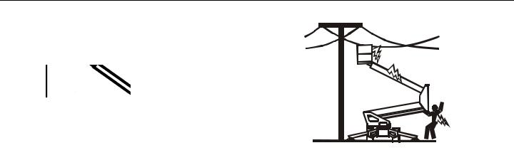
Electrocution Hazards
• This machine is not insulated and does not provide protection from contact or proximity to electrical current.
• Maintain safe distance from electrical lines, apparatus, or any energized (exposed or insulated) parts according to the Minimum Approach Distance (MAD) as shown in Table 1-1.
• Allow for machine movement and electrical line swaying.
3121197 |
– JLG Lift – |
1-5 |

SECTION 1 - SAFETY
Table 1-1. Minimum Approach Distances (M.A.D.)
Voltage Range |
|
MINIMUM APPROACH DISTANCE |
(Phase to Phase) |
|
in Feet (Meters) |
|
|
|
0to50KV |
|
10 (3) |
|
|
|
Over 50KV to200KV |
|
15 (5) |
|
|
|
Over 200 KVto 350 KV |
|
20 (6) |
|
|
|
Over 350 KVto 500 KV |
|
25 (8) |
|
|
|
Over 500 KVto 750 KV |
|
35 (11) |
|
|
|
Over750KV to1000KV |
|
45(14) |
|
|
|
NOTE: This requirement |
shall apply except where |
|
employer, local or governmental regulations are more stringent.
•Maintain a clearance of at least 10 ft. (3m) between any part of the machine and its occupants, their tools, and their equipment from any electrical line or apparatus carrying up to 50,000 volts. One foot additional clearance is required for every additional 30,000 volts or less.
•The minimum approach distance may be reduced if insulating barriers are installed to prevent contact, and the barriers are rated for the voltage of the line being guarded. These barriers shall not be part of (or attached to) the machine. The minimum approach distance shall be reduced to a distance within the designed working dimensions of the insulating barrier. This determination shall be made by a qualified person in accordance with the employer, local, or governmental requirements for work practices near energized equipment
DO NOT MANEUVER MACHINE OR PERSONNEL INSIDE PROHIBITED ZONE (MSAD). ASSUME ALL ELECTRICAL PARTS AND WIRING ARE ENERGIZED UNLESS KNOWN OTHERWISE.
1-6 |
– JLG Lift – |
3121197 |
SECTION 1 - SAFETY
Tipping Hazards
•The user should be familiar with the surface before operating. Do not exceed the allowable sideslope and grade while operating.
•Do not elevate platform while on a soft surface.
•Before operating on floors, bridges, trucks, and other surfaces, check allowable capacity of the surfaces.
•Never exceed the maximum platform capacity. Distribute loads evenly on platform floor.
•Do not raise the platform unless the machine is on firm surfaces and outriggers are properly set.
•Keep the chassis and outriggers of the machine at least 2 ft. (0.6m) from holes, bumps, drop-offs, obstructions, debris, concealed holes, and other potential hazards on the floor/surface.
•Do not push or pull any object with the boom.
•Never attempt to use the machine as a crane with platform attached. Do not tie-off machine to any adjacent structure.
•Do not operate the machine when wind conditions exceed 28 mph (12.5 m/s).
•Do not increase the surface area of the platform or the load. Increase of the area exposed to the wind will decrease stability and could result in a tip-over.
•Do not increase the platform size with unauthorized platform extensions or attachments.
•If boom assembly or platform is in a position that one or more outriggers are off the ground, all persons must be removed before attempting to stabilize the machine. Use cranes, forklift trucks, or other appropriate equipment to stabilize machine.
3121197 |
– JLG Lift – |
1-7 |

SECTION 1 - SAFETY
Crushing and Collision Hazards
•Approved head gear must be worn by all operating and ground personnel.
•Check work area for clearances overhead, on sides, and bottom of platform when lifting or lowering platform, and driving.
•During operation, keep all body parts inside platform railing.
•Always post a lookout when driving in areas where vision is obstructed.
•Keep non-operating personnel at least 6 ft. (1.8m) away from machine during all operations.
•Under all travel conditions, the operator must limit travel speed according to conditions of ground surface, congestion, visibility, slope, location of personnel, and other factors causing hazards of collision or injury to personnel.
•Exercise extreme caution at all times to prevent obstacles from striking or interfering with operating controls and persons in the platform.
•Be sure that operators of other overhead and floor level machines are aware of the aerial work platform’s presence. Disconnect power to overhead cranes.
•Warn personnel not to work, stand, or walk under a raised boom or platform. Position barricades on floor if necessary.
1-8 |
– JLG Lift – |
3121197 |
SECTION 1 - SAFETY
1.5LIFTING, AND HAULING
•Never allow personnel in platform while towing, lifting, or hauling the machine.
•Ensure boom is in the stowed position and the transportation latch is locked prior to towing, lifting or hauling. The platform must be completely empty.
•When lifting machine, lift only at designated areas of the machine. Lift the unit with equipment of adequate capacity.
•Refer to the Machine Operation section of this manual for lifting information.
1.6TOWING HAZARDS
Safe and proper usage of the trailer mounted boom lift is essential to avoid accidents. Unsafe use; separation of trailer mounted boom lift from tow vehicle or loss of control of the trailer mounted boom lift or trailer/tow vehicle combination could result in death or serious injury. Common causes for trailer accidents include:
a.Driving too fast for conditions;
b.Failure to adjust handling while towing a trailer;
c.Trailer improperly coupled to the hitch;
d.Incorrect use of safety chains;
e.Incorrect use of breakaway brake;
f.Mismatch of trailer and hitch;
g.Unsafe tires, lug nuts or wheels;
h.Inoperable brakes, lights or mirrors;
i.Modifying the trailer;
j.Inadequate tow vehicle or towing hitch; and
k.Not properly maintaining the trailer structure.
1.7ADDITIONAL HAZARDS / SAFETY
•Do not use machine as a ground for welding.
•When performing welding or metal cutting operations, precautions must be taken to protect the chassis from direct exposure to weld and metal cutting spatter.
•Do not refuel the machine with the engine running.
•Battery fluid is highly corrosive. Avoid contact with skin and clothing at all times.
•Charge batteries only in a well ventilated area.
3121197 |
– JLG Lift – |
1-9 |

SECTION 1 - SAFETY
DO NOT OPERATE THE MACHINE WHEN WIND CONDITIONS EXCEED 28 MPH (12.5 M/
S).
|
|
|
Table 1-2. Beaufort Scale (For Reference Only) |
||
|
|
|
|
|
|
Beaufort |
Wind Speed |
Description |
Land Conditions |
||
Number |
mph |
m/s |
|||
|
|
||||
|
|
|
|
|
|
0 |
0 |
0-0.2 |
Calm |
Calm.Smokerises vertically. |
|
|
|
|
|
|
|
1 |
1-3 |
0.3-1.5 |
Lightair |
Windmotionvisiblein smoke. |
|
|
|
|
|
|
|
2 |
4-7 |
1.6-3.3 |
Lightbreeze |
Windfelt onexposedskin.Leavesrustle. |
|
|
|
|
|
|
|
3 |
8-12 |
3.4-5.4 |
Gentlebreeze |
Leavesandsmallertwigsinconstantmotion. |
|
|
|
|
|
|
|
4 |
13-18 |
5.5-7.9 |
Moderatebreeze |
Dust and loose paperraised.Small branches begin tomove. |
|
|
|
|
|
|
|
5 |
19-24 |
8.0-10.7 |
Freshbreeze |
Smallertreessway. |
|
|
|
|
|
|
|
6 |
25-31 |
10.8-13.8 |
Strongbreeze |
Largebranchesinmotion.Whistlingheardinoverheadwires.Umbrellause |
|
|
|
|
|
becomesdifficult. |
|
|
|
|
|
|
|
7 |
32-38 |
13.9-17.1 |
NearGale/ModerateGale |
Wholetrees in motion. Effortneededtowalk against thewind. |
|
|
|
|
|
|
|
8 |
39-46 |
17.2-20.7 |
FreshGale |
Twigsbrokenfromtrees.Cars veer onroad. |
|
|
|
|
|
|
|
9 |
47-54 |
20.8-24.4 |
StrongGale |
Lightstructuredamage. |
|
|
|
|
|
|
|
1-10 |
– JLG Lift – |
3121197 |

SECTION 2 - USER RESPONSIBILITIES, MACHINE PREPARATION, AND INSPECTION
SECTION 2. USER RESPONSIBILITIES, MACHINE PREPARATION, AND INSPECTION
2.1 PERSONNEL TRAINING
The aerial platform is a personnel handling device; so it is necessary that it be operated and maintained only by trained personnel.
Persons under the influence of drugs or alcohol or who are subject to seizures, dizziness or loss of physical control must not operate this machine.
Operator Training
Operator training must cover:
1.Use and limitations of the controls in the platform and at the ground, emergency controls and safety systems.
2.Control labels, instructions, and warnings on the machine.
3.Rules of the employer and government regulations.
4.Use of approved fall protection device.
5.Enough knowledge of the mechanical operation of the machine to recognize a malfunction or potential malfunction.
6.The safest means to operate the machine where overhead obstructions, other moving equipment, and obstacles, depressions, holes, drop-offs.
7.Means to avoid the hazards of unprotected electrical conductors.
8.Specific job requirements or machine application.
Training Supervision
Training must be done under the supervision of a qualified person in an open area free of obstructions until the trainee has developed the ability to safely control and operate the machine.
Operator Responsibility
The operator must be instructed that he/she has the responsibility and authority to shut down the machine in case of a malfunction or other unsafe condition of either the machine or the job site.
3121197 |
– JLG Lift – |
2-1 |

SECTION 2 - USER RESPONSIBILITIES, MACHINE PREPARATION, AND INSPECTION
2.2 PREPARATION, INSPECTION, AND MAINTENANCE
The following table covers the periodic machine inspections and maintenance required by JLG Industries, Inc. Consult local regulations for further requirements for aerial work platforms. The frequency of inspections and maintenance must be increased as necessary when the machine is used in a harsh or hostile environment, if the machine is used with increased frequency, or if the machine is used in a severe manner.
JLG INDUSTRIES, INC. RECOGNIZES A FACTORY-QUALIFIED SERVICE TECHNICIAN AS A PERSON WHO HAS SUCCESSFULLY COMPLETED THE JLG SERVICE TRAINING SCHOOL FOR THE SPECIFIC JLG PRODUCT MODEL.
2-2 |
– JLG Lift – |
3121197 |

SECTION 2 - USER RESPONSIBILITIES, MACHINE PREPARATION, AND INSPECTION
Table 2-1.Inspection and Maintenance Table
|
Type |
Frequency |
Primary |
Service |
Reference |
|
Responsibility |
Qualification |
|||
|
|
|
|
||
|
|
|
|
|
|
Pre-StartInspection |
Beforeusingeachday;or |
Useror Operator |
Useror Operator |
OperatorandSafetyManual |
|
|
|
wheneverthere’sanOperatorchange. |
|
|
|
|
|
|
|
|
|
Pre-DeliveryInspection(SeeNote) |
Beforeeachsale,lease, orrental delivery. |
Owner,Dealer,or User |
QualifiedJLG Mechanic |
Service and Maintenance Manual |
|
|
|
|
|
|
andapplicableJLGinspectionform |
|
|
|
|
|
|
FrequentInspection |
Inservicefor3 months or150 hours,whichevercomesfirst; |
Owner,Dealer,or User |
QualifiedJLG Mechanic |
Service andMaintenance Manual |
|
|
|
or |
|
|
andapplicableJLGinspectionform |
|
|
Out ofserviceforaperiod ofmore than3months; |
|
|
|
|
|
or |
|
|
|
|
|
Purchasedused. |
|
|
|
|
|
|
|
|
|
Annual MachineInspection |
Annually,no laterthan 13 monthsfromthedate ofprior |
Owner,Dealer, or User |
FactoryQualified |
Service and Maintenance Manual |
|
|
|
inspection. |
|
Service Technician |
andapplicableJLGinspectionform |
|
|
|
|
(Recommended) |
|
|
|
|
|
|
|
PreventativeMaintenance |
At intervals asspecifiedintheServiceand Maintenance |
Owner,Dealer,or User |
QualifiedJLG Mechanic |
Service andMaintenance Manual |
|
|
|
Manual. |
|
|
|
|
|
|
|
|
|
NOTE: |
Inspection forms are available from JLG. Use the Service and Maintenance Manual to perform inspections. |
|
|||
|
|
|
|
|
|
3121197 |
– JLG Lift – |
2-3 |

SECTION 2 - USER RESPONSIBILITIES, MACHINE PREPARATION, AND INSPECTION
Pre-Start Inspection
The Pre-Start Inspection should include each of the following:
1.Cleanliness – Check all surfaces for leakage (oil, fuel, or battery fluid) or foreign objects. Report any leakage to the proper maintenance personnel.
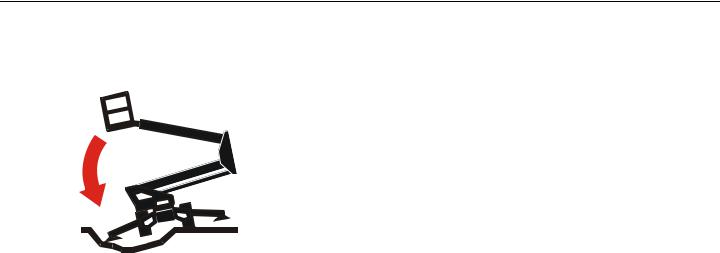
2.Structure - Inspect the machine structure for dents, damage, weld or parent metal cracks or other discrepancies.
ParentMetal Crack |
WeldCrack |
3.Decals and Placards – Check all for cleanliness and legibility. Make sure none of the decals and placards are missing. Make sure all illegible decals and placards are cleaned or replaced.
4.Operation and Safety Manuals – Make sure a copy of the Operator and Safety Manual, AEM Safety Manual (ANSI markets only), and ANSI Manual of Responsibilities (ANSI markets only) is enclosed in the weather resistant storage container.
5.“Walk-Around” Inspection – Refer to Figure 2-3.
6.Battery – Charge as required.
7.Fuel (Combustion Engine Powered Machines) – Add the proper fuel as necessary.
8.Engine Oil Supply - Ensure the engine oil level is at the Full mark on the dipstick and the filler cap is secure.
9.Hydraulic Oil – Check the hydraulic oil level. Ensure hydraulic oil is added as required.
10.Accessories/Attachments - Reference the Operator and Safety Manual of each attachment or accessory installed upon the machine for specific inspection, operation, and maintenance instructions.
11.Function Check – Once the “Walk-Around” Inspection is complete, perform a functional check of all systems in an area free of overhead and ground level obstructions. Refer to Section 4 for more specific operating instructions.
2-4 |
– JLG Lift – |
3121197 |

SECTION 2 - USER RESPONSIBILITIES, MACHINE PREPARATION, AND INSPECTION
IF THE MACHINE DOES NOT OPERATE PROPERLY, TURN OFF THE MACHINE IMMEDIATELY! REPORT THE PROBLEM TO THE PROPER MAINTENANCE PERSONNEL. DO NOT OPERATE THE MACHINE UNTIL IT IS DECLARED SAFE FOR OPERATION.
Function Check
Perform the Function Check as follows:
1.From the ground control console with no load in the platform:
a.Check that all guards protecting the function control switches and controllers are in place;
b.Operate all functions;
c.Ensure that all machine functions are disabled when the Emergency Stop Button is pushed in.
d.Ensure all boom functions stop when the function enable switch is released.
2.With the platform in the stowed position:
a.Check that telescope out and lift up above horizontal are disabled with the outriggers retracted and the boom out of transport position.
3.From the platform control console:
a.Ensure that the control console is firmly secured in the proper location;
b.Check that all guards protecting the function control switches and controllers are in place;
c.Operate all functions;
d.Ensure all boom functions stop when the function enable switch is released.
e.Ensure that all machine functions are disabled when the Emergency Stop Button is pushed in.
3121197 |
– JLG Lift – |
2-5 |
SECTION 2 - USER RESPONSIBILITIES, MACHINE PREPARATION, AND INSPECTION
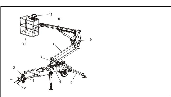
1. Coupler
2. SafetyChains(N/AonCE& AustralianSpec)
3. TongueJack
4. ParkingBrake
5. Outrigger
6. Chassis
7. Turntable
8. LowerBoom
9. Upright
10. Boom
11. Platform
12. PlatformConsole
Figure 2-1. Basic Nomenclature
2-6 |
– JLG Lift – |
3121197 |

SECTION 2 - USER RESPONSIBILITIES, MACHINE PREPARATION, AND INSPECTION
This page left blank intentionally.
3121197 |
– JLG Lift – |
2-7 |

SECTION 2 - USER RESPONSIBILITIES, MACHINE PREPARATION, AND INSPECTION
T350
Figure 2-2. Daily Walk-Around Inspection - Sheet 1 of 3
2-8 |
– JLG Lift – |
3121197 |
 Loading...