


 Loading...
Operation & Safety,
Service & Maintenance, &
Illustrated Parts Manual Supplement
JLG
LOAD
SENSING
SYSTEM
Scissors Lift Products
P/N
3124288
July 26, 2013
INTRODUCTION
SECTION A. INTRODUCTION - MAINTENANCE SAFETY
PRECAUTIONS
A GENERAL
This section contains the general safety precautions which must be observed during maintenance of the aerial platform. It is of utmost importance that maintenance personnel pay strict attention to these warnings and precautions to avoid possible injury to themselves or others, or damage to the equipment. A maintenance program must be followed to ensure that the machine is safe to operate.
MODIFICATION OF THE MACHINE WITHOUT CERTIFICATION BY A RESPONSIBLE AUTHORITY THAT THE MACHINE IS AT LEAST AS SAFE AS ORIGINALLY MANUFACTURED, IS A SAFETY VIOLATION.
The specific precautions to be observed during maintenance are inserted at the appropriate point in the manual. These precautions are, for the most part, those that apply when servicing hydraulic and larger machine component parts.
Your safety, and that of others, is the first consideration when engaging in the maintenance of equipment. Always be conscious of weight. Never attempt to move heavy parts without the aid of a mechanical device. Do not allow heavy objects to rest in an unstable position. When raising a portion of the equipment, ensure that adequate support is provided.
SINCE THE MACHINE MANUFACTURER HAS NO DIRECT CONTROL OVER THE FIELD INSPECTION AND MAINTENANCE, SAFETY IN THIS AREA IS THE RESPONSIBILITY OF THE OWNER/ OPERATOR.
B HYDRAULIC SYSTEM SAFETY
It should be noted that the machines hydraulic systems operate at extremely high, potentially dangerous pressures. Every effort should be made to relieve any system pressure prior to disconnecting or removing any portion of the system.
C MAINTENANCE
FAILURE TO COMPLY WITH SAFETY PRECAUTIONS LISTED IN THIS SECTION MAY RESULT IN MACHINE DAMAGE, PERSONNEL INJURY OR DEATH AND IS A SAFETY VIOLATION.
•REMOVE ALL RINGS, WATCHES AND JEWELRY WHEN PERFORMING ANY MAINTENANCE.
•DO NOT WEAR LONG HAIR UNRESTRAINED, OR LOOSE-FITTING CLOTHING AND NECKTIES WHICH ARE APT TO BECOME CAUGHT ON OR ENTANGLED IN EQUIPMENT.
•OBSERVE AND OBEY ALL WARNINGS AND CAUTIONS ON MACHINE AND IN SERVICEMANUAL.
•KEEP OIL, GREASE, WATER, ETC. WIPED FROM STANDING SURFACES AND HAND HOLDS.
•NEVER WORK UNDER AN ELEVATED SIZZOR UNTIL PLATFORM HAS BEEN SAFELY RESTRAINED FROM ANY MOVEMENT BY BLOCKING OR OVERHEAD SLING, OR BOOM SAFETY PROP HAS BEEN ENGAGED.
•BEFORE MAKING ADJUSTMENTS, LUBRICATING OR PERFORMING ANY OTHER MAINTENANCE, SHUT OFF ALL POWER CONTROLS.
•BATTERY SHOULD ALWAYS BE DISCONNECTEDDURING REPLACEMENT OF ELECTRICAL COMPONENTS.
•KEEP ALL SUPPORT EQUIPMENT AND ATTACHMENTS STOWED IN THEIR PROPER PLACE.
•USE ONLY APPROVED, NONFLAMMABLE CLEANING SOLVENTS.
3124288 |
– JLG Lift – |
A-1 |

INTRODUCTION
|
|
REVISION LOG |
Original Issue |
- |
June 13, 2003 |
Revised |
- |
July 28, 2003 |
Revised |
- |
August 11, 2003 |
Revised |
- |
September 12, 2003 |
Revised |
- |
March 1, 2004 |
Revised |
- |
October 15, 2004 |
Revised |
- |
July 15, 2006 |
Revised |
- |
October 26, 2007 |
Revised |
- |
June 4, 2010 |
Revised |
- |
March 31, 2011 |
Revised |
- |
March 1, 2012 |
Revised |
- |
August 11, 2012 |
Revised |
- |
January 30, 2013 |
Revised |
- |
July 26, 2013 |
A-2 |
– JLG Lift – |
3124288 |

TABLE OF CONTENTS
TABLE OF CONTENTS |
|
SUBJECT - SECTION, PARAGRAPH |
PAGE NO. |
SECTION A - INTRODUCTION - MAINTENANCE SAFETY PRECAUTIONS |
|
A General . . . . . . . . . . . . . . . . . . . . . . . . . . . . . . . . . . . . . . . . . . . . . . . . . . . . . . . . . . . . . . . . . . . . . .A-1 B Hydraulic System Safety . . . . . . . . . . . . . . . . . . . . . . . . . . . . . . . . . . . . . . . . . . . . . . . . . . . . . . . . .A-1 C Maintenance . . . . . . . . . . . . . . . . . . . . . . . . . . . . . . . . . . . . . . . . . . . . . . . . . . . . . . . . . . . . . . . . . .A-1
SECTION 1 - ANALYZER OPERATION - ALL
1.1 Introduction & Operation. . . . . . . . . . . . . . . . . . . . . . . . . . . . . . . . . . . . . . . . . . . . . . . . . . . . . . . . .1-1 1.2 Using the Analyzer . . . . . . . . . . . . . . . . . . . . . . . . . . . . . . . . . . . . . . . . . . . . . . . . . . . . . . . . . . . . .1-1 1.3 Changing the Access Level of the Hand Held Analyzer. . . . . . . . . . . . . . . . . . . . . . . . . . . . . . . . .1-2 1.4 Viewing & Adjusting Parameters Using the Hand Held Analyzer. . . . . . . . . . . . . . . . . . . . . . . . . .1-3
SECTION 2 - OPERATION - (LE, MRT, RTS)
2.1 Connecting the JLG Control System Analyzer (LE, MRT & RTS). . . . . . . . . . . . . . . . . . . . . . . . . .2-1 2.2 Help Menu & Fault Codes (LE, MRT & RTS) . . . . . . . . . . . . . . . . . . . . . . . . . . . . . . . . . . . . . . . . .2-1 2.3 Diagnostic Menu (LE, MRT & RTS). . . . . . . . . . . . . . . . . . . . . . . . . . . . . . . . . . . . . . . . . . . . . . . . .2-3 2.4 Personalities (LE, MRT & RTS) . . . . . . . . . . . . . . . . . . . . . . . . . . . . . . . . . . . . . . . . . . . . . . . . . . . .2-5 2.5 Machine Setup Menu (LE, MRT & RTS) . . . . . . . . . . . . . . . . . . . . . . . . . . . . . . . . . . . . . . . . . . . . .2-6 2.6 Calibration Menu (LE, MRT & RTS). . . . . . . . . . . . . . . . . . . . . . . . . . . . . . . . . . . . . . . . . . . . . . . . .2-6 2.7 JLG Workstation in the Sky™ Accessories . . . . . . . . . . . . . . . . . . . . . . . . . . . . . . . . . . . . . . . . . . .2-9
SECTION 3 - OPERATION - (ES, RT)
3.1 Connecting the JLG Control System Analyzer (ES & RT) . . . . . . . . . . . . . . . . . . . . . . . . . . . . . . .3-1 3.2 Help Menu & Fault Codes (ES & RT) . . . . . . . . . . . . . . . . . . . . . . . . . . . . . . . . . . . . . . . . . . . . . . .3-1 3.3 Diagnostic Menu (ES & RT) . . . . . . . . . . . . . . . . . . . . . . . . . . . . . . . . . . . . . . . . . . . . . . . . . . . . . .3-3 3.4 Personalities (ES & RT) . . . . . . . . . . . . . . . . . . . . . . . . . . . . . . . . . . . . . . . . . . . . . . . . . . . . . . . . . .3-3 3.5 Machine Setup Menu (ES & RT) . . . . . . . . . . . . . . . . . . . . . . . . . . . . . . . . . . . . . . . . . . . . . . . . . . .3-4 3.6 Calibration Menu (ES & RT) . . . . . . . . . . . . . . . . . . . . . . . . . . . . . . . . . . . . . . . . . . . . . . . . . . . . . .3-4
SECTION 4 - OPERATION - (RS)
4.1 Connecting the JLG Control System Analyzer (RS) . . . . . . . . . . . . . . . . . . . . . . . . . . . . . . . . . . . .4-1 4.2 Help Menu & Fault Codes (RS). . . . . . . . . . . . . . . . . . . . . . . . . . . . . . . . . . . . . . . . . . . . . . . . . . . .4-1 4.3 Diagnostic Menu (RS) . . . . . . . . . . . . . . . . . . . . . . . . . . . . . . . . . . . . . . . . . . . . . . . . . . . . . . . . . . .4-2 4.4 Personalities MENU (RS) . . . . . . . . . . . . . . . . . . . . . . . . . . . . . . . . . . . . . . . . . . . . . . . . . . . . . . . .4-3 4.5 Calibration Menu (RS) . . . . . . . . . . . . . . . . . . . . . . . . . . . . . . . . . . . . . . . . . . . . . . . . . . . . . . . . . . .4-3
Angle Sensor Calibration (RS Only) . . . . . . . . . . . . . . . . . . . . . . . . . . . . . . . . . . . . . . . . . . . .4-3 4.6 Load Sensing System Calibration (RS Only) . . . . . . . . . . . . . . . . . . . . . . . . . . . . . . . . . . . . . . . . .4-5
SECTION 5 - SERVICE - (LE, MRT, RTS, ES, RT)
5.1 Description . . . . . . . . . . . . . . . . . . . . . . . . . . . . . . . . . . . . . . . . . . . . . . . . . . . . . . . . . . . . . . . . . . .5-1 5.2 Calibration . . . . . . . . . . . . . . . . . . . . . . . . . . . . . . . . . . . . . . . . . . . . . . . . . . . . . . . . . . . . . . . . . . . .5-2 Procedure . . . . . . . . . . . . . . . . . . . . . . . . . . . . . . . . . . . . . . . . . . . . . . . . . . . . . . . . . . . . . . . .5-2 Testing & Evaluation . . . . . . . . . . . . . . . . . . . . . . . . . . . . . . . . . . . . . . . . . . . . . . . . . . . . . . . .5-2
5.3 Troubleshooting . . . . . . . . . . . . . . . . . . . . . . . . . . . . . . . . . . . . . . . . . . . . . . . . . . . . . . . . . . . . . . .5-4
SECTION 6 - SERVICE - (RS)
6.1 Description (RS) . . . . . . . . . . . . . . . . . . . . . . . . . . . . . . . . . . . . . . . . . . . . . . . . . . . . . . . . . . . . . . .6-1 6.2 Calibration (RS) . . . . . . . . . . . . . . . . . . . . . . . . . . . . . . . . . . . . . . . . . . . . . . . . . . . . . . . . . . . . . . . .6-1 Angle Sensor Calibration Procedure (RS). . . . . . . . . . . . . . . . . . . . . . . . . . . . . . . . . . . . . . . .6-1 Platform Load Sensing System Calibration Procedure (RS) . . . . . . . . . . . . . . . . . . . . . . . . .6-1
6.3 Testing and Evaluation (RS) . . . . . . . . . . . . . . . . . . . . . . . . . . . . . . . . . . . . . . . . . . . . . . . . . . . . . .6-2 6.4 LSS Troubleshooting (RS) . . . . . . . . . . . . . . . . . . . . . . . . . . . . . . . . . . . . . . . . . . . . . . . . . . . . . . .6-3 6.5 LSS Component Removal/Installation (RS) . . . . . . . . . . . . . . . . . . . . . . . . . . . . . . . . . . . . . . . . . .6-5 Pressure Transducer Removal (RS) . . . . . . . . . . . . . . . . . . . . . . . . . . . . . . . . . . . . . . . . . . . .6-5 Pressure Transducer Installation (RS). . . . . . . . . . . . . . . . . . . . . . . . . . . . . . . . . . . . . . . . . . .6-5
3124288 |
– JLG Lift – |
i |

TABLE OF CONTENTS (Continued)
10RS Angle Sensor Removal (RS) . . . . . . . . . . . . . . . . . . . . . . . . . . . . . . . . . . . . . . . . . . . . .6-6 10RS Angle Sensor Installation (RS). . . . . . . . . . . . . . . . . . . . . . . . . . . . . . . . . . . . . . . . . . . .6-6 6RS Angle Sensor Removal (RS) . . . . . . . . . . . . . . . . . . . . . . . . . . . . . . . . . . . . . . . . . . . . . .6-6 6RS Angle Sensor Installation (RS). . . . . . . . . . . . . . . . . . . . . . . . . . . . . . . . . . . . . . . . . . . . .6-6 LSS Connector Pin Assignments (RS) . . . . . . . . . . . . . . . . . . . . . . . . . . . . . . . . . . . . . . . . . .6-7
SECTION 7 - PARTS
7-1 Load Sensing System Installation (260MRT, M3369/M4069 & 3369LE/4069LE) . . . . . . . . . . . . .7-2 7-2 Load Sensing System Installation (500RTS) . . . . . . . . . . . . . . . . . . . . . . . . . . . . . . . . . . . . . . . . .7-6 7-3 Load Sensing System Installation (1930ES/2032ES/2630ES/ 2646ES/3246ES) . . . . . . . . . . . . .7-8 7-4 Load Sensing System Installation (6RS/10RS/1932RS/3248RS). . . . . . . . . . . . . . . . . . . . . . . . . .7-12 7-5 Load Sensing System Installation (3394RT/4394RT) . . . . . . . . . . . . . . . . . . . . . . . . . . . . . . . . . . .7-14
|
LIST OF FIGURES |
|
FIGURE NO. |
TITLE |
PAGE NO. |
2-1. Module Analyzer Flow Chart . . . . . . . . . . . . . . . . . . . . . . . . . . . . . . . . . . . . . . . . . . . . . . . . . . . . . .2-8 3-1. Module Analyzer Flow Chart . . . . . . . . . . . . . . . . . . . . . . . . . . . . . . . . . . . . . . . . . . . . . . . . . . . . . .3-6 5-1. Load Sense Module . . . . . . . . . . . . . . . . . . . . . . . . . . . . . . . . . . . . . . . . . . . . . . . . . . . . . . . . . . . .5-1 5-2. LSS Module Load Cell Connector Pinout (J5, J6, J7, J8) . . . . . . . . . . . . . . . . . . . . . . . . . . . . . . .5-10 5-3. 260MRT Wiring Diagram . . . . . . . . . . . . . . . . . . . . . . . . . . . . . . . . . . . . . . . . . . . . . . . . . . . . . . . . .5-11 5-4. M3369/M4069 & 3369LE/4069LE Wiring Diagram . . . . . . . . . . . . . . . . . . . . . . . . . . . . . . . . . . . . .5-12 5-5. 500RTS Wiring Diagram . . . . . . . . . . . . . . . . . . . . . . . . . . . . . . . . . . . . . . . . . . . . . . . . . . . . . . . . .5-13 5-6. ES Wiring Diagram . . . . . . . . . . . . . . . . . . . . . . . . . . . . . . . . . . . . . . . . . . . . . . . . . . . . . . . . . . . . .5-14 5-7. RT Wiring Diagram . . . . . . . . . . . . . . . . . . . . . . . . . . . . . . . . . . . . . . . . . . . . . . . . . . . . . . . . . . . . .5-15 6-1. LSS Pressure Transducers Location - 1932RS/6RS. . . . . . . . . . . . . . . . . . . . . . . . . . . . . . . . . . . .6-5 6-2. LSS Pressure Transducers Location - 3248RS/10RS. . . . . . . . . . . . . . . . . . . . . . . . . . . . . . . . . . .6-5 6-3. LSS - Scissor Arm Angle Sensor - (RS) . . . . . . . . . . . . . . . . . . . . . . . . . . . . . . . . . . . . . . . . . . . . .6-6 6-4. LSS - Electrical Component Schematic - (RS) . . . . . . . . . . . . . . . . . . . . . . . . . . . . . . . . . . . . . . . .6-8
|
LIST OF TABLES |
|
TABLE NO. |
TITLE |
PAGE NO. |
2-1 LSS Fault Codes (LE, MRT and RTS) . . . . . . . . . . . . . . . . . . . . . . . . . . . . . . . . . . . . . . . . . . . . . . .2-1 2-2 Diagnostic Menu Descriptions (LE, MRT & RTS) . . . . . . . . . . . . . . . . . . . . . . . . . . . . . . . . . . . . . .2-3 2-3 Personalities Menu Description (LE, MRT, RTS) . . . . . . . . . . . . . . . . . . . . . . . . . . . . . . . . . . . . . .2-5 2-4 Machine Setup Menu . . . . . . . . . . . . . . . . . . . . . . . . . . . . . . . . . . . . . . . . . . . . . . . . . . . . . . . . . . .2-6 2-5 Calibration Values . . . . . . . . . . . . . . . . . . . . . . . . . . . . . . . . . . . . . . . . . . . . . . . . . . . . . . . . . . . . . .2-7 2-6 LSS Module Guidelines. . . . . . . . . . . . . . . . . . . . . . . . . . . . . . . . . . . . . . . . . . . . . . . . . . . . . . . . . .2-9 3-1 LSS Fault Codes (LE, MRT and RTS) . . . . . . . . . . . . . . . . . . . . . . . . . . . . . . . . . . . . . . . . . . . . . . .3-1 3-2 Diagnostic Menu Descriptions (ES & RT) . . . . . . . . . . . . . . . . . . . . . . . . . . . . . . . . . . . . . . . . . . . .3-3 3-3 Personalities (ES & RT) . . . . . . . . . . . . . . . . . . . . . . . . . . . . . . . . . . . . . . . . . . . . . . . . . . . . . . . . . .3-3 3-4 Machine Setup . . . . . . . . . . . . . . . . . . . . . . . . . . . . . . . . . . . . . . . . . . . . . . . . . . . . . . . . . . . . . . . .3-4 3-5 Calibration Values . . . . . . . . . . . . . . . . . . . . . . . . . . . . . . . . . . . . . . . . . . . . . . . . . . . . . . . . . . . . . .3-5 4-1 LSS Fault Codes (RS ONLY). . . . . . . . . . . . . . . . . . . . . . . . . . . . . . . . . . . . . . . . . . . . . . . . . . . . . .4-1 4-2 Diagnostic Menu Descriptions (RS) . . . . . . . . . . . . . . . . . . . . . . . . . . . . . . . . . . . . . . . . . . . . . . . .4-2 4-3 Personalities Menu Description (RS) . . . . . . . . . . . . . . . . . . . . . . . . . . . . . . . . . . . . . . . . . . . . . . .4-3 4-4 Angle Sensor Calibration Failure Troubleshooting (RS Only) . . . . . . . . . . . . . . . . . . . . . . . . . . . .4-5 4-5 Load Calibration Failure Troubleshooting (RS Only) . . . . . . . . . . . . . . . . . . . . . . . . . . . . . . . . . . .4-7 5-1 LSS Troubleshooting Chart - General. . . . . . . . . . . . . . . . . . . . . . . . . . . . . . . . . . . . . . . . . . . . . . .5-4 5-2 LSS Troubleshooting Chart - Calibration . . . . . . . . . . . . . . . . . . . . . . . . . . . . . . . . . . . . . . . . . . . .5-5
ii |
– JLG Lift – |
3124288 |

TABLE OF CONTENTS
5-3 LSS Troubleshooting Chart - Measurement Performance . . . . . . . . . . . . . . . . . . . . . . . . . . . . . . .5-6 5-4 LSS Troubleshooting Chart - Host System Functionality . . . . . . . . . . . . . . . . . . . . . . . . . . . . . . . .5-8 5-5 LSS Module System Interface Connector - Power & Digital (J1 - Grey) . . . . . . . . . . . . . . . . . . . .5-10 5-6 LSS Module System Interface Connector – Communication (J1 - Black) . . . . . . . . . . . . . . . . . . .5-10 5-7 LSS Module Load Cell Connector Pinout (J5, J6, J7, J8) . . . . . . . . . . . . . . . . . . . . . . . . . . . . . . .5-10 6-1 Platform Calibration Weight - RS. . . . . . . . . . . . . . . . . . . . . . . . . . . . . . . . . . . . . . . . . . . . . . . . . . .6-1 6-2 System Activation Height - RS . . . . . . . . . . . . . . . . . . . . . . . . . . . . . . . . . . . . . . . . . . . . . . . . . . . .6-2 6-3 LSS Troubleshooting - RS. . . . . . . . . . . . . . . . . . . . . . . . . . . . . . . . . . . . . . . . . . . . . . . . . . . . . . . .6-3 6-4 Connections to Host Control System (J1-Black) (RS) . . . . . . . . . . . . . . . . . . . . . . . . . . . . . . . . . .6-7 6-5 Connections to Host Control System (J2-Blue) (RS) . . . . . . . . . . . . . . . . . . . . . . . . . . . . . . . . . . .6-7 6-6 Angle Sensor Connector Pinout (RS) . . . . . . . . . . . . . . . . . . . . . . . . . . . . . . . . . . . . . . . . . . . . . . .6-7 6-7 Pressure Transducer Connector Pinout (RS) . . . . . . . . . . . . . . . . . . . . . . . . . . . . . . . . . . . . . . . . .6-7
3124288 |
– JLG Lift – |
iii |

TABLE OF CONTENTS (Continued)
 NOTES:
iv |
– JLG Lift – |
3124288 |
SECTION 1 - ANALYZER OPERATION - ALL
SECTION 1. ANALYZER OPERATION - ALL
NOTE: This manual is intended as a supplement to the individual machine’s Operators and Safety Manual.
1.1INTRODUCTION & OPERATION
NOTE: It is the responsibility of the owner/user/operator/lessor/lessee to read & understand this manual and the machine Operators & Safety Manual and to prevent overloading the platform. Do not operate a machine with a disconnected or inoperative Load Sensing System.
The JLG-designed Load Sensing System (LSS) measures platform load. If the actual platform load exceeds the selected Rated Load, the following will occur:
1.The Overload Visual Warning Indicator will flash at the selected control position (platform or ground).
2.The Platform and Ground Alarms will sound 5 seconds On, and 2 seconds Off.
3.All normal movement will be prevented from the platform control position (optional - ground control functions may be prevented).
4.Further movement is permitted by:
a.Removing the excess platform load until actual platform load is less than Rated Load.
b.By an authorized person at the ground control position (optional - ground control functions may be prevented).
THE LOAD SENSING SYSTEM MUST BE CALIBRATED WHEN ONE OR MORE OF THE FOLLOWING CONDITIONS OCCUR:
a.LSS System initial installation
b.LSS Module replacement
c.LSS Sensor removal or replacement
d.Addition or removal of certain platform mounted accessories. (Refer to Calibration in Section 2)
e.Platform is removed, replaced, repaired or shows evidence of impact.
THE LOAD SENSING SYSTEM REQUIRES PERIODIC FUNCTION VERIFICATION NOT TO EXCEED 6 MONTHS FROM PREVIOUS VERIFICATION. REFER TO TESTING & EVALUATION IN SECTION 2.
Calibration of the Load Sensing System is performed by connecting the JLG Analyzer (Analyzer Kit, JLG part no. 2901443). All calibration procedures are menu driven through the use of the Analyzer.
1.2USING THE ANALYZER
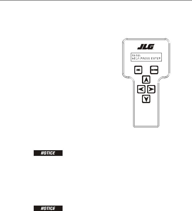
With the machine power on and the analyzer connected properly, the analyzer will display the following:
HELP:
PRESS ENTER
At this point, using the RIGHT and LEFT arrow keys, you can move between the top level menu items. To select a displayed menu item, press ENTER. To cancel a selected menu item, press ESC.; then you will be able to scroll using the right and left arrow keys to select a different menu item.
If you press ENTER at the HELP: PRESS ENTER display and there are no faults, the Analyzer will display EVERYTHING OK. In the event of a fault, the Analyzer will display a Help Message.
If ENTER is pressed again, the Analyzer will display LOGGED HELP, a record of the last 16 faults. Use the left and right arrow keys to scroll through the fault log. To return to the top level menu, press the ESC key twice.
When a top level menu entry is selected, a new set of menu items will be displayed.
Pressing ENTER while viewing any of the above menu entries will display additional sub-menus. Typically, the sub-menu is where parameter information is displayed or changed. You may only view Personality settings while in Access Level 2. Access Level 1 is required to change Personality settings and calibrate.
3124288 |
– JLG Lift – |
1-1 |
SECTION 1 - ANALYZER OPERATION - ALL
The ESC key may be used to leave a sub-menu at any time.
1.3CHANGING THE ACCESS LEVEL OF THE HAND HELD ANALYZER
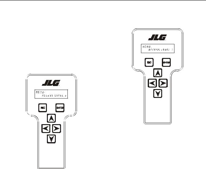
When the analyzer is first connected, you will be in access level 2 which enables you to only view most settings which cannot be changed until you enter a password to advance to a lower level. This ensures that a setting cannot be accidentally altered. To change the access level, the correct password must be entered. To enter the password, scroll to the ACCESS LEVEL menu. For example:
MENU:
ACCESS LEVEL 2
Press ENTER to select the ACCESS LEVEL menu.
Using the UP or DOWN arrow keys, enter the first digit of the password, 3.
Then using the RIGHT arrow key, position the cursor to the right one space to enter the second digit of the password.
Use the UP or DOWN arrow key to enter the second digit of the password which is 33271.
Continue using the arrow keys until all the remaining digits of the password is shown.
Once the correct password is displayed, press ENTER. The access level should display the following, if the password was entered correctly:
MENU:
ACCESS LEVEL 1
Repeat the above steps if the correct access level is not displayed or you can not adjust the personality settings.
1-2 |
– JLG Lift – |
3124288 |
SECTION 1 - ANALYZER OPERATION - ALL
1.4VIEWING & ADJUSTING PARAMETERS USING THE HAND HELD ANALYZER
Once you have gained access to level 1, and a personality item is selected, press the UP or DOWN arrow keys to adjust its value, for example:
PERSONALITIES:
DRIVE ACCEL 3.0s
PERSONALITIES:
OVR DEBNCE 3.0s
There will be a minimum and maximum for the value to ensure efficient operation. The Value will not increase if the UP arrow is pressed when at the maximum value nor will the value decrease if the DOWN arrow is pressed and the value is at the minimum value for any particular personality. If the value does not change when pressing the up and down arrows, check the access level to ensure you are at Access Level 1.
3124288 |
– JLG Lift – |
1-3 |

SECTION 1 - ANALYZER OPERATION - ALL
 NOTES:
1-4 |
– JLG Lift – |
3124288 |

SECTION 2 - OPERATION - (LE, MRT, RTS)
SECTION 2. OPERATION - (LE, MRT, RTS)
2.1CONNECTING THE JLG CONTROL SYSTEM ANALYZER (LE, MRT & RTS)
THE LOAD SENSING SYSTEM MODULE HAS AN INDEPENDENT ANALYZER CONNECTION LOCATED NEAR THE MODULE. DO NOT CONFUSE IT WITH THE ANALYZER CONNECTION FROM THE HOST CONTROL SYSTEM.
1.Connect the cable supplied with the Analyzer to the LSS Module located beneath the platform and connect the remaining end of the cable to the analyzer.
NOTE: The cable has a four-pin connector at each end of the cable; The cable cannot be connected backwards.
2.Power-up the Control System by turning the key to the Platform or Ground position and pulling both emergency stop buttons.
2.2HELP MENU & FAULT CODES (LE, MRT & RTS)
The Help Menu is a troubleshooting tool to communicate detected System Faults to the technician. The following table documents the Faults for the Load Sensing System. To access the Help Menu, use the LEFT and RIGHT arrow keys to select HELP: PRESS ENTER from the Top Level Menu. Press the ENTER key to view the menu.
When accessing the Help Menu, the JLG Analyzer will display EVERYTHING OK if the platform is not overloaded and no difficulties are detected. Otherwise, the JLG Analyzer will display OVERLOADED.
In the event of difficulty, the user can press ENTER again to display Logged Help, which is a record of the last 16 Fault Messages. The following table lists each Help/ Logged Message, the Flash Code (for each Fault, the module will flash the two-digit code on its LED) triggered by the Fault, and a Description of the Situation (cause).
|
|
Table 2-1. LSS Fault Codes (LE, MRT and RTS) |
|
|
|
|
|
Help/Logged |
Flash |
Description of Situation |
|
Message |
Code |
||
|
|||
|
|
|
|
Everything OK |
LED ON |
The "Normal" Help Message |
|
|
|
|
|
<MIN CAL |
|
Calibration attempt Unsuccessful, Empty Platform appears to weigh too little. Improper Model Selection (Machine |
|
|
|
Setup) may cause the LSS Module to expect the wrong Empty Platform Weight. This also may be caused by a damaged |
|
|
|
sensor or associated wiring. Finally, this condition may occur if mechanical interference between the platform and sup- |
|
|
|
port structure exists (all weight must transfer through sensors). |
|
|
|
|
|
>MAX CAL |
|
Calibration attempt Unsuccessful, Empty Platform appears to weigh too much. This situation has the same root causes |
|
|
|
as the "<MIN CAL" Fault Message. |
|
|
|
|
|
BATT TOO LOW |
4/1 |
Incoming Supply Voltage <9.0 Vdc. The control system’s battery voltage is too low due to excessive electrical load or |
|
|
|
discharge. |
|
|
|
|
|
BATT TOO HIGH |
4/4 |
Incoming Supply Voltage >34.0 Vdc. The control system’s battery voltage is too high. This may be due to over-charg- |
|
|
|
ing or improper charger operation. |
|
|
|
|
|
CELL #1 ERROR |
8/1 |
Cell #1’s Bridge <2V, >3V, or could not read Cell #1’s Internal Memory. This situation indicates damage to the sensor |
|
|
|
or its wiring. |
|
|
|
|
|
CELL #2 ERROR |
8/2 |
Cell #2’s Bridge <2V, >3V, or could not read Cell #2’s Internal Memory. This situation indicates damage to the sensor |
|
|
|
or its wiring. |
|
|
|
|
|
CELL #3 ERROR |
8/3 |
Cell #3’s Bridge <2V, >3V, or could not read Cell #3’s Internal Memory. This situation indicates damage to the sensor |
|
|
|
or its wiring. |
|
|
|
|
|
CELL #4 ERROR |
8/4 |
Cell #4’s Bridge <2V, >3V, or could not read Cell #4’s Internal Memory. This situation indicates damage to the sensor |
|
|
|
or its wiring. |
|
|
|
|
|
WATCHDOG RST |
9/1 |
Microprocessor’s Watchdog Timer Triggered. This is an indication that the LSS Module has been exposed to excessive |
|
|
|
electrical noise, or has experienced a hardware difficulty. |
|
|
|
|
|
EEPROM ERROR |
9/2 |
Memory used to retain Personality/Machine Setup/Calibration has been corrupted and must be reset by verifying all |
|
|
|
entries and re-calibrating. |
|
|
|
|
|
NO CAL |
9/3 |
Calibration has not been successfully completed. A new LSS Module will display this message until properly cali- |
|
|
|
brated. |
|
|
|
|
3124288 |
– JLG Lift – |
2-1 |

SECTION 2 - OPERATION - (LE, MRT, RTS)
|
|
Table 2-1. LSS Fault Codes (LE, MRT and RTS) |
|
|
|
|
|
Help/Logged |
Flash |
Description of Situation |
|
Message |
Code |
||
|
|||
|
|
|
|
INTERNAL ERR |
9/9 |
Pin excitation <4.25 V. The sensors may be excessively loading the excitation supply, or the LSS Module may have |
|
|
|
hardware difficulty. |
|
|
|
|
|
|
|
High Side Driver Error. The load attached to OUT1 or OUT2 is shorted to battery or ground and has been detected by the |
|
|
|
LSS module. |
|
|
|
|
|
|
|
DRDY Interrupt from A/D missing. This may indicate an LSS Module hardware difficulty. |
|
|
|
|
2-2 |
– JLG Lift – |
3124288 |

SECTION 2 - OPERATION - (LE, MRT, RTS)
2.3DIAGNOSTIC MENU (LE, MRT & RTS)
The Diagnostic Load Menu is another troubleshooting tool for the Load Sensing System. Sensor and status information is presented in real-time for the technician. Several sub-menus exist to organize the data.
Note that the Diagnostic Menu changes based on MODEL Parameter in the Machine Setup Menu (some displays are suppressed). The information presented in the following table will be proper when MODEL=3369LE/4069LE/ 500RTS or 260MRT (refer to Machine Setup Menu).
To access the Diagnostic Menu, use the LEFT and RIGHT Arrow keys to select DIAGNOSTICS from the Top Level Menu. Press the ENTER key to view the menu.
Press the LEFT and RIGHT Arrow keys to view the displays and select the various sub-menus (PIN 1, PIN 2, etc.). To access a sub-menu, press the ENTER key. Once in a sub-menu, press the LEFT and RIGHT Arrow keys to view the various displays (just like a Top Level menu). To exit a sub-menu, press the ESC key.
The table below details the structure of the Diagnostic Menu, and describes the meaning of each piece of information presented.
Table 2-2. Diagnostic Menu Descriptions (LE, MRT & RTS)
Diagnostics Menu |
Parameter (Displayed |
Parameter Value |
|
|
(Displayed on Analyzer 2nd |
Description |
|||
(Displayed on Analyzer 1st Line) |
on Analyzer 2nd Line) |
|||
Line) |
|
|||
|
|
|
||
|
|
|
|
|
|
PLTLOAD |
+XXXX LBS or Kg |
Displays (Total Measured Force – Empty Platform |
|
|
|
|
Calibration) |
|
|
|
|
|
|
|
PLTGROS |
+XXXX LBS or Kg |
Displays Total Measured Force (Sum of Pins 1 thru 4 |
|
|
|
|
LOAD) |
|
|
|
|
|
|
|
OVERLOADED? |
Yes / No |
Displays Current LSS Module Overload Status |
|
|
|
|
|
|
CELL 1: |
|
|
|
|
|
|
|
|
|
|
LOAD |
+XXXX LBS or Kg |
Displays Calibrated Cell Reading in Current Units |
|
|
|
|
|
|
|
RDG |
+XX.XXXX mV/V |
Displays Pin Reading in mV/V |
|
|
|
|
|
|
|
INPUT |
+XX.XXXX mV |
Displays Pin Reading in mV |
|
|
|
|
|
|
|
GAIN |
XXXX.X |
Displays calibration factor from pin |
|
|
|
|
|
|
CELL 2: |
|
|
|
|
|
|
|
|
|
|
LOAD |
+XXXX LBS or Kg |
Displays Calibrated Cell Reading in Current Units |
|
|
|
|
|
|
|
RDG |
+XX.XXXX mV/V |
Displays Pin Reading in mV/V |
|
|
|
|
|
|
|
INPUT |
+XX.XXXX mV |
Displays Pin Reading in mV |
|
|
|
|
|
|
|
GAIN |
XXXX.X |
Displays calibration factor from pin |
|
|
|
|
|
|
CELL 3: |
|
|
|
|
|
|
|
|
|
|
LOAD |
+XXXX LBS or Kg |
Displays Calibrated Cell Reading in Current Units |
|
|
|
|
|
|
|
RDG |
+XX.XXXX mV/V |
Displays Pin Reading in mV/V |
|
|
|
|
|
|
|
INPUT |
+XX.XXXX mV |
Displays Pin Reading in mV |
|
|
|
|
|
|
|
GAIN |
XXXX.X |
Displays calibration factor from pin |
|
|
|
|
|
|
CELL 4: |
|
|
|
|
|
|
|
|
|
|
LOAD |
+XXXX LBS or Kg |
Displays Calibrated Cell Reading in Current Units |
|
|
|
|
|
|
|
RDG |
+XX.XXXX mV/V |
Displays Pin Reading in mV/V |
|
|
|
|
|
|
|
INPUT |
+XX.XXXX mV |
Displays Pin Reading in mV |
|
|
|
|
|
|
|
GAIN |
XXXX.X |
Displays calibration factor from pin |
|
|
|
|
|
|
SYSTEM: |
|
|
|
|
|
|
|
|
|
|
OVLOAD STAT |
OFF / ON |
State of Overload Status Digital Output |
|
|
|
|
|
|
|
WARNING |
OFF / ON |
State of Warning Digital Output |
|
|
|
|
|
|
|
MOT INHIBIT |
NO / YES |
Status of Internal Motion Inhibit Flag |
|
|
|
|
|
|
|
MOTION #1 |
OFF / ON |
Status of Digital Input #1 |
|
|
|
|
|
3124288 |
– JLG Lift – |
2-3 |

SECTION 2 - OPERATION - (LE, MRT, RTS)
Table 2-2. Diagnostic Menu Descriptions (LE, MRT & RTS)
Diagnostics Menu |
Parameter (Displayed |
Parameter Value |
|
|
(Displayed on Analyzer 2nd |
Description |
|||
(Displayed on Analyzer 1st Line) |
on Analyzer 2nd Line) |
|||
Line) |
|
|||
|
|
|
||
|
|
|
|
|
|
MOTION #2 |
OFF / ON |
Status of Digital Input #2 |
|
|
|
|
|
|
|
MOTION #3* |
OFF / ON |
Status of Digital Input #3 |
|
|
|
|
|
|
|
BATTERY |
XX.XXV |
Displays Current Battery Voltage |
|
|
|
|
|
|
|
EXCITE |
X.XXXXV |
Displays Load Pin Excitation Voltage |
|
|
|
|
|
|
|
TEMP |
+/-XXX.X Deg C |
Display the Temperature Sensed by the LSS Module |
|
|
|
|
for Scissor Pin Compensation |
|
|
|
|
|
|
VERSIONS: |
|
|
|
|
|
|
|
|
|
|
SOFTWARE |
PX.XX |
Displays LSS Module Software Version |
|
|
|
|
|
|
|
HARDWARE |
X |
Display LSS Module Hardware Revision |
|
|
|
|
|
|
|
ANALYZER |
VX.XXXX |
Displays Analyzer Software Version |
|
|
|
|
|
2-4 |
– JLG Lift – |
3124288 |

SECTION 2 - OPERATION - (LE, MRT, RTS)
2.4PERSONALITIES (LE, MRT & RTS)
NOTE: The following parameter adjust performance of the Load Sensing System. All adjustments must be made at access level 1 (33271).
THE SETTINGS UNDER THE FACTORY MENU OPTION ARE UNIQUE TO EACH MODULE. THESE SETTINGS ARE NOT TO BE ALTERED . IN THE EVENT THAT THESE SETTINGS ARE ALTERED, CONTACT JLG WITH THE SERIAL NUMBER OF THE MODULE.
Table 2-3. Personalities Menu Description (LE, MRT, RTS)
Personalities |
Parameter (Displayed |
|
|
|
|
|
|
(Displayed on |
Description |
4069LE |
3369LE |
500RTS |
260MRT |
||
On Analyzer 2nd line) |
|||||||
Analyzer 1st line) |
|
|
|
|
|
||
|
|
|
|
|
|
||
|
|
|
|
|
No |
|
|
|
|
|
|
|
Extensions- |
|
|
|
|
|
|
|
2628 LBS |
|
|
|
|
|
|
|
(1192 KGS) |
|
|
|
|
|
|
|
Single or |
|
|
|
OVERLD XXXX |
Displays/adjusts the overload limit for this |
550 LBS |
1042 LBS |
Dual |
1320 LBS |
|
|
LBS (KGS) |
AWP |
(378 KGS) |
(473 KGS) |
Extensions |
(599 KGS) |
|
|
|
|
|
|
2083 LBS |
|
|
|
|
|
|
|
(945 KGS) |
|
|
|
|
|
|
|
MegaDeck- |
|
|
|
|
|
|
|
1574 LBS |
|
|
|
|
|
|
|
(714 KGS) |
|
|
|
|
|
|
|
|
|
|
|
ACC’Y XXXX LBS |
Displays/adjusts a de-rating for |
0 LBS |
0 LBS |
0 LBS |
0 LBS |
|
|
(KGS) |
Accessories |
(0KGS) |
(0KGS) |
(0KGS) |
(0KGS) |
|
|
|
|
|
|
|
|
|
|
MTN DELAY XS |
Displays/adjusts the delay between motion |
2 SEC |
2 SEC |
2 SEC |
2 SEC |
|
|
ceasing and evaluation of overload |
||||||
|
|
|
|
|
|
||
|
|
|
|
|
|
|
|
|
OVR DBNCE XS |
Displays/adjusts the de-bounce delay |
3 SEC |
3 SEC |
3 SEC |
3 SEC |
|
|
before an overload |
||||||
|
|
|
|
|
|
||
|
|
|
|
|
|
|
|
|
OVR HOLD XS |
Displays/adjusts the minimum delay |
5 SEC |
5 SEC |
5 SEC |
5 SEC |
|
|
before an overload can be released. |
||||||
|
|
|
|
|
|
||
|
|
|
|
|
|
|
|
FACTORY |
#1 GAIN |
Displays/calibrates the LSS Module analog |
|
|
X |
|
|
|
X.XXXX |
channel gain |
|
|
|
|
|
|
#1 ZERO |
Displays/calibrates the LSS Module analog |
|
|
X |
|
|
|
+X.XXXX mV |
channel offset. |
|
|
|
|
|
|
|
|
|
|
|
|
|
|
#2 GAIN |
Displays/calibrates the LSS Module analog |
|
|
X |
|
|
|
X.XXXX |
channel gain |
|
|
|
|
|
|
|
|
|
|
|
|
|
|
#2 ZERO |
Displays/calibrates the LSS Module analog |
|
|
X |
|
|
|
+X.XXXX mV |
channel offset |
|
|
|
|
|
|
#3 GAIN |
Displays/calibrates the LSS Module analog |
|
|
X |
|
|
|
X.XXXX |
channel gain |
|
|
|
|
|
|
|
|
|
|
|
|
|
|
#3ZERO |
Displays/calibrates the LSS Module analog |
|
|
X |
|
|
|
+X.XXXX mV |
channel offset |
|
|
|
|
|
|
|
|
|
|
|
|
|
|
#4 GAIN |
Displays/calibrates the LSS Module analog |
|
|
X |
|
|
|
X.XXXX |
channel gain |
|
|
|
|
|
|
#4 ZERO |
Displays/calibrates the LSS Module analog |
|
|
X |
|
|
|
+X.XXXX mV |
channel offset |
|
|
|
|
|
|
|
|
|
|
|
|
|
|
EX GAIN |
Displays/calibrates the LSS Module excita- |
|
|
X |
|
|
|
X.XXXX |
tion measurement gain |
|
|
|
|
|
|
|
|
|
|
|
|
|
|
TEMP OFFS |
Displays/calibrates the LSS Module internal |
|
|
X |
|
|
|
+/- XXX.X |
temp sensor |
|
|
|
|
3124288 |
– JLG Lift – |
2-5 |
SECTION 2 - OPERATION - (LE, MRT, RTS)
2.5MACHINE SETUP MENU (LE, MRT & RTS)
The Machine Setup Menu is used to configure the Load Sensing System for application on a particular JLG model, and select the desired force units (i.e. pounds or kilograms). In addition, the technician can trigger the LSS Module to restore Defaults to all Personalities Parameters by changing the MODEL to any other selection, and then re-selecting proper model.
Note that Diagnostics and Personalities Menus change based on MODEL Parameter (some displays are suppressed).
To access the Machine Setup Menu, use the LEFT and RIGHT Arrow keys to select MACHINE SETUP from the Top Level Menu. Press the ENTER key to view the menu. Press the LEFT and RIGHT Arrow keys to view the displays.
The following table details the structure of the Machine Setup Menu, and describes the meaning of each parameter.
Table 2-4. Machine Setup Menu
Parameter |
Parameter Value |
|
|
(Displayed on |
|
||
(Displayed on |
Description |
||
Analyzer 2nd |
|||
Analyzer 2nd Line) |
|
||
Line) |
|
||
|
|
||
|
|
|
|
|
=BOOM LIFT |
Displays/adjusts Model Selec- |
|
|
=4069LE |
tion. Must be set to proper |
|
MODEL: |
=3369LE |
model for this application. |
|
=500RTS |
(Scissor available after soft- |
||
|
|||
|
=260MRT |
ware V7.00) |
|
|
=Scissor |
|
|
|
|
|
|
UNITS: |
=LBS |
Displays/adjusts global force |
|
=Kg |
units |
||
|
|||
|
|
|
2.6CALIBRATION MENU (LE, MRT & RTS)
The Calibration Menu is used to zero the Empty Platform weight.
To access the Calibration Menu, use the LEFT and RIGHT Arrow keys to select CALIBRATION from the Top Level Menu. Press the ENTER key to view the menu.
NOTE: The Calibration Menu is not available in Access Level 2.
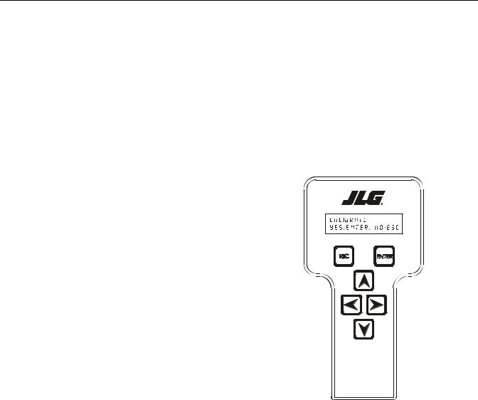
Upon entry to the Calibration Menu, the LSS Module shall communicate to the Analyzer:
CALIBRATE:
YES:ENTER, NO:ESC
Pressing the ESC key will return the user to the top level menu and not disturb the prior calibration information.
2-6 |
– JLG Lift – |
3124288 |
SECTION 2 - OPERATION - (LE, MRT, RTS)
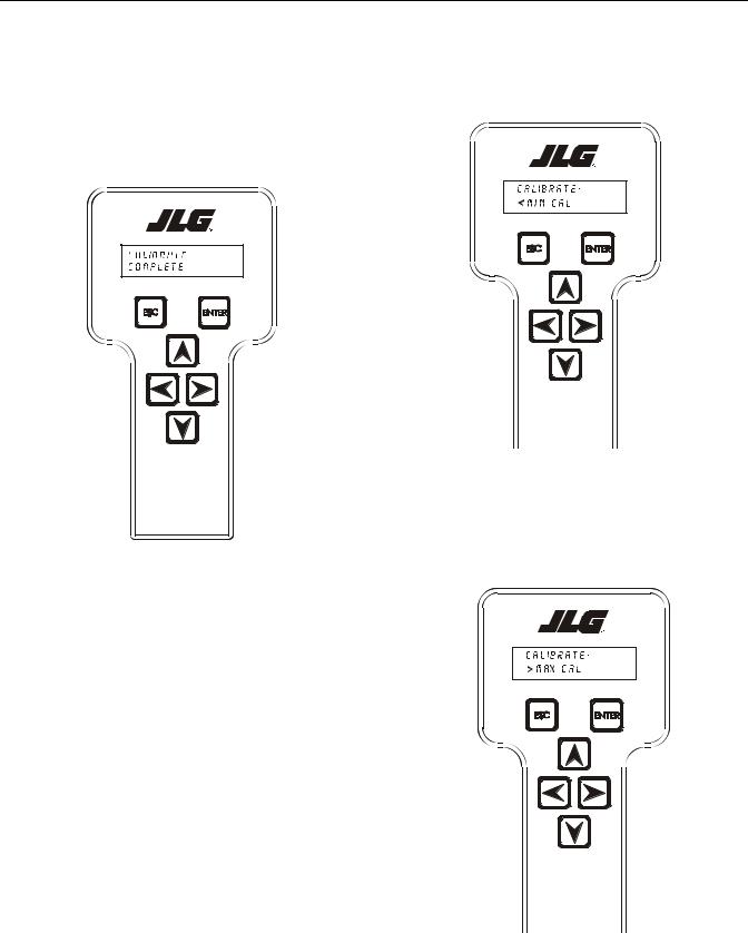
Pressing the ENTER key will confirm that the platform is empty (except for factory-installed options outside the Rated Load). The LSS Module will calculate the total of all load cell readings and ensure that the total is greater than minimum calibration value, but less than maximum calibration value. If successful, the Analyzer will show the following:
If the empty platform weight is less than minimum calibration value, the calibration attempt will be unsuccessful and the Analyzer will show the following:
CALIBRATE:
COMPLETE
|
Table 2-5. Calibration Values |
|
||
|
|
|
|
|
MODELS |
4069LE |
3969LE |
500RTS |
260MRT |
Minimum Cali- |
850 lb |
850 lb |
1100 lb |
750 lb |
bration Value |
(385 kg) |
(385 kg) |
(499 kg) |
(340 kg) |
|
|
|
|
|
Maximum Cali- |
1425 lb |
1425 lb |
2950 lb |
1250 lb |
bration Value |
(646 kg) |
(646 kg) |
(1338 kg) |
(567 kg) |
|
|
|
|
|
CALIBRATE: < MIN CAL
If the empty platform weight is greater than maximum calibration value, the calibration attempt will be unsuccessful and the Analyzer will show the following:
CALIBRATE: > MAX CAL
3124288 |
– JLG Lift – |
2-7 |
SECTION 2 - OPERATION - (LE, MRT, RTS)
|
|
|
|
|
|
|
|
|
|
|
|
|
|
|
|
|
|
|
|
|
|
|
|
|
|
|
|
|
|
|
|
|
|
|
|
|
|
|
|
|
|
|
|
|
|
|
|
|
|
|
|
|
|
|
MACHINESETUP |
|
|
|
|
|
|
500MS;1,2250, |
3,5,10secretary |
|
|
|
-ZERO+/1#X.XXXX |
X.XXXX#2GAIN |
|
CALIBRATIONS -+/#2ZEROX.XXXX |
YES:ENTER,NO:ESC X.XXXX#3GAIN |
|
|
|
|
-+/#3ZEROX.XXXX |
X.XXXX#4GAIN |
-+/#4ZEROX.XXXX |
GAINEXCITEX.XXXX |
+/OFFSTEMPXXX.XC |
|||||||||||||||||||||||||||||
|
|
MODEL=BOOMLIFT 4069LE,3369LE,500RTS, 260MRT,SCISSOR FACTORYHOLD=0,OWR 100,50,25,10, |
|
|
|
|||||||||||||||||||||||||||||||||||||||||||||||||
|
|
|
|
|
|
|
|
|
LBS/KG = UNITS |
|
|
|
|
|
|
|
|
|
|
|
|
|
|
|
|
|
|
|
|
|
|
|
|
|
|
|
|
|
|
|
|
|
|
|
|
|
|
|
|
|
|
|
|
|
|
|
|
|
|
|
|
|
|
|
GAINX.XXXX |
|
|
|
|
|
|
|
|
|
|
|
|
|
|
|
|
|
|
|
|
|
|
|
|
|
|
|
|
|
|
|
|
|
|
|
|
|
|
|
|
|
|
|
|
|
|
|
|
|
|
|
|
|
|
|
|
|
|
|
|
|
|
|
|
|
|
|
|
|
|
|
|
|
|
|
|
|
|
|
|
|
|
|
|
|
|
|
|
|
|
|
|
|
|
|
|
|
|
|
|
|
|
|
|
|
|
|
|
|
#1 |
|
|
|
|
|
|
|
|
|
|
|
|
|
|
|
|
|
|
|
|
|
|
|
|
|
|
|
|
|
|
|
|
|
|
|
|
|
|
|
|
|
|
|
|
|
|
|
|
|
|
|
|
|
|
|
|
|
|
|
|
|
|
|
|
|
|
|
|
|
|
|
|
|
|
|
|
|
|
|
|
|
|
|
|
|
|
|
|
|
|
|
|
|
|
|
|
|
|
|
|
|
|
|
|
|
|
|
|
|
|
|
|
|
|
|
|
|
|
|
|
|
|
|
|
|
|
|
|
|
|
|
|
|
|
|
|
|
|
|
|
|
|
|
|
|
|
|
|
|
|
|
|
||
|
|
|
|
|
|
|
|
|
|
|
|
|
|
|
|
|
|
|
|
|
|
|
|
|
|
|
|
|
|
|
|
|
|
|
|
|
|
|
|
|
|
|
|
|
|
|
|
|
|
|
|
|
|
|
|
|
|
|
|
|
|
|
|
|
|
|
|
|
|
|
|
|
|
|
|
|
|
|
|
|
|
|
|
|
|
|
|
|
|
|
|
|
|
|
|
|
|
|
|
|
|
|
|
|
|
|
|
|
|
|
|
|
|
|
|
|
|
|
|
|
|
|
|
|
|
|
|
|
|
|
|
|
|
|
|
|
|
|
|
|
|
|
|
|
|
|
|
|
|
|
|
|
|
|
|
|
|
|
|
|
|
|
||
PERSONALITIES |
|
|
|
OWRDENCE=0, |
10,25,50,100, |
250,500MS;1,2 |
3,5,10secretary |
|
|
|
|
|
|
|
|
|
|
|
|
|
|
|
|
|
|
|
|
|
|
|
|
|
|
|
|
|
|
|
|
|
|
|
|
|
|
|
|
|
|
|
|
|||
|
|
|
|
|
|
|
|
|
|
|
|
|
|
|
|
|
|
|
|
|
|
|
|
|
|
|
|
|
|
|
|
|
|
|
|
|
|
|
|
|
|
|
|
|
|
|
|
|
|
|
||||
|
|
|
MTNDLY=0, |
10,25,50,100, |
250,500MS;1,2 |
3,5,10secretary |
|
|
|
|
|
|
|
|
|
|
|
|
|
|
|
|
|
|
|
|
|
|
|
|
|
|
|
|
|
|
|
|
|
|
|
|
|
|
|
|
|
|
|
Chart |
||||
|
|
|
|
|
|
|
|
|
|
|
|
|
|
|
|
|
|
|
|
|
|
|
|
|
|
|
|
|
|
|
|
|
|
|
|
|
|
|
|
|
|
|
|
|
|
|
|
|
|
|||||
|
|
|
|
|
ACCYXXXX |
LBS,KG |
|
|
|
|
|
|
|
|
|
|
|
|
|
|
|
|
|
|
|
|
|
|
|
|
|
|
|
|
|
|
|
|
|
|
|
|
|
|
|
|
|
|
|
|||||
|
|
|
|
|
|
|
|
|
|
|
|
|
|
|
|
|
|
|
|
|
|
|
|
|
|
|
|
|
|
|
|
|
|
|
|
|
|
|
|
|
|
|
|
|
|
|
|
|
|
|
|
AnalyzerFlow |
||
|
|
|
|
|
|
|
|
|
|
|
|
|
|
|
|
|
|
|
|
|
|
|
|
|
|
|
|
|
|
|
|
|
|
|
|
|
|
|
|
|
|
|
|
|
|
|
|
|
|
|
|
|||
|
|
|
|
|
OVERLDXXXX |
LBS,KG |
|
|
|
|
|
|
|
|
|
|
|
|
|
|
|
|
|
|
|
|
|
|
|
|
|
|
|
|
|
|
|
|
|
|
|
|
|
|
|
|
|
|
|
|||||
|
|
|
|
|
|
|
|
|
|
|
|
|
|
|
|
|
|
|
|
|
|
|
|
|
|
|
|
|
|
|
|
|
|
|
|
|
|
|
|
|
|
|
|
|
|
|
|
|
|
|
|
|||
|
|
|
|
|
|
|
|
|
|
|
|
|
|
|
|
|
|
|
|
|
|
|
|
|
|
|
|
|
|
|
|
|
|
|
|
|
|
|
|
|
|
|
|
|
|
|
|
|
|
|
|
|
|
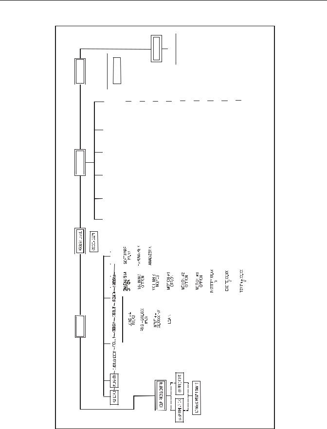
2-1. Module |
|
|
|
|
|
|
|
|
|
|
|
|
|
|
|
|
|
|
|
|
|
|
|
|
|
|
|
|
|
|
|
|
|
|
|
|
|
|
|
|
|
|
|
|
|
|
|
|
|
|
|
|
|||
|
|
|
|
|
|
|
|
|
VERSIONS |
|
|
|
|
|
|
|
|
|
|
|
|
|
|
|
|
|
|
|
|
|
|
|
|
|
|
|
|
|
|
|
|
|
|
|
|
|
|
|
|
|
|
|
|
|
|
|
|
|
|
|
|
|
|
|
|
|
|
|
|
|
|
|
|
|
|
|
|
|
|
|
|
|
|
|
|
|
|
|
|
|
|
|
|
|
|
|
|
|
|
|
|
|
|
|
|
|
|
||
|
|
|
|
|
|
|
|
|
|
|
|
|
|
|
|
|
|
|
|
|
|
|
|
|
|
|
|
|
|
|
|
|
|
|
|
|
|
|
|
|
|
|
|
|
|
|
|
|
|
|
|
|||
|
|
|
|
|
|
|
|
|
|
|
|
|
|
|
|
|
|
|
|
|
|
|
|
|
|
|
|
|
|
|
|
|
|
|
|
|
|
|
|
|
|
|
|
|
|
|
|
|
|
|
|
|
|
|
|
|
|
|
|
|
|
|
|
|
|
|
|
|
|
|
|
|
|
|
|
|
|
|
|
|
|
|
|
|
|
|
|
|
|
|
|
|
|
|
|
|
|
|
|
|
|
|
|
|
|
|
|
|
|
DIAGNOSTICS |
|
|
|
|
|
|
|
|
|
|
|
|
|
|
|
|
|
|
|
|
|
|
|
|
|
|
|
|
|
|
|
|
|
|
|
|
|
|
|
|
|
|
|
|
|
|
|
|
|
|
|
|
|
Figure |
|
|
|
|
|
|
|
|
|
|
|
|
|
|
|
|
|
|
|
|
|
|
|
|
|
|
|
|
|
|
|
|
|
|
|
|
|
|
|
|
|
|
|
|
|
|
|
|
|
|
|
|
|
||
|
|
|
|
|
|
|
|
|
|
|
|
|
|
|
|
|
|
|
|
|
|
|
|
|
|
|
|
|
|
|
|
|
|
|
|
|
|
|
|
|
|
|
|
|
|
|
|
|
|
|
|
|
||
|
|
|
|
|
|
|
|
|
|
|
|
|
|
|
|
|
|
|
|
|
|
|
|
|
|
|
|
|
|
|
|
|
|
|
|
|
|
|
|
|
|
|
|
|
|
|
|
|
|
|
|
|
||
|
|
|
|
|
|
|
|
|
|
|
|
|
|
|
|
|
|
|
|
|
|
|
|
|
|
|
|
|
|
|
|
|
|
|
|
|
|
|
|
|
|
|
|
|
|
|
|
|
|
|
|
|
||
|
|
|
|
|
|
|
|
|
|
|
|
|
|
|
|
|
|
|
|
|
|
|
|
|
|
|
|
|
|
|
|
|
|
|
|
|
|
|
|
|
|
|
|
|
|
|
|
|
|
|
|
|
||
|
|
|
|
|
|
|
|
|
|
|
|
|
|
|
|
|
|
|
|
|
|
|
|
|
|
|
|
|
|
|
|
|
|
|
|
|
|
|
|
|
|
|
|
|
|
|
|
|
|
|
||||
|
|
|
|
|
|
|
|
|
|
|
|
|
|
|
|
|
|
|
|
|
|
|
|
|
|
|
|
|
|
|
|
|
|
|
|
|
|
|
|
|
|
|
|
|
|
|
|
|
|
|
|
|
|
|
|
|
|
|
|
|
|
|
|
|
|
|
|
|
|
|
|
|
|
|
|
|
|
|
|
|
|
|
|
|
|
|
|
|
|
|
|
|
|
|
|
|
|
|
|
|
|
|
|
|
|
|
|
|
|
|
|
|
|
|
|
|
|
|
|
|
|
|
|
|
|
|
|
|
|
|
|
|
|
|
|
|
|
|
|
|
|
|
|
|
|
|
|
|
|
|
|
|
|
|
|
|
|
|
|
|
|
|
|
|
|
|
|
|
|
|
|
|
|
|
|
|
|
|
|
|
|
|
|
|
|
|
|
|
|
|
|
|
|
|
|
|
|
|
|
|
|
|
|
|
|
|
|
|
|
|
|
|
|
|
|
|
|
|
|
|
|
|
|
|
|
|
|
|
|
|
|
|
|
|
|
|
|
|
|
|
|
|
|
|
|
|
|
|
|
|
|
|
|
|
|
|
|
|
|
|
|
|
|
|
|
|
|
|
|
|
|
|
|
|
|
|
|
|
|
|
|
|
|
|
|
|
|
|
|
|
|
|
|
|
|
|
|
|
|
|
|
|
|
|
|
|
|
|
|
|
|
|
|
|
|
|
|
|
|
|
|
|
|
|
|
|
|
|
|
|
|
|
|
|
|
|
|
|
|
|
|
|
|
|
|
|
|
|
|
|
|
|
|
|
|
|
|
|
|
|
|
|
|
|
|
|
|
|
|
|
|
|
|
|
|
|
|
|
|
|
|
|
||
|
|
|
|
|
|
|
|
|
|
|
|
|
|
|
|
|
|
|
|
|
|
|
|
|
|
|
|
|
|
|
|
|
|
|
|
|
|
|
|
|
|
|
|
|
|
|
|
|
|
|
|
|
|
|
|
|
|
|
|
|
|
|
|
|
|
|
|
|
|
|
|
|
|
|
|
|
|
|
|
|
|
|
|
|
|
|
|
|
|
|
|
|
|
|
|
|
|
|
|
|
|
|
|
|
|
|
|
|
|
|
|
|
|
|
|
|
|
|
|
|
|
|
|
|
|
|
|
|
|
|
|
|
|
|
|
|
|
|
|
|
|
|
|
|
|
|
|
|
|
|
|
|
|
|
|
|
|
|
|
|
|
|
|
|
|
|
|
|
|
|
|
|
|
|
|
|
|
|
|
|
|
|
|
|
|
|
|
|
|
|
|
|
|
|
|
|
|
|
|
|
|
|
|
|
|
|
|
|
|
|
|
|
|
|
|
|
|
|
|
|
|
|
|
|
|
|
|
|
|
|
|
|
|
|
|
|
|
|
|
|
|
|
|
|
|
|
|
|
|
|
|
|
|
|
|
|
|
|
|
|
|
|
|
|
|
|
|
|
|
|
|
|
|
|
|
|
|
|
|
|
|
|
|
|
|
|
|
|
|
|
|
|
|
|
|
|
|
|
|
|
|
|
|
|
|
|
|
|
|
|
|
|
|
|
|
|
|
|
|
|
|
|
|
|
|
|
|
|
|
|
|
|
|
|
|
|
|
|
|
|
|
|
|
|
|
|
|
|
|
|
|
|
|
|
|
|
|
|
|
|
|
|
|
|
|
|
|
|
|
|
|
|
|
|
|
|
|
|
|
|
|
|
|
|
|
|
|
|
|
|
|
|
|
|
|
|
|
|
|
|
|
|
|
|
|
|
|
|
|
|
|
|
|
|
|
|
|
|
|
|
|
|
|
|
|
|
|
|
|
|
|
|
|
|
|
|
|
|
|
|
|
|
|
|
|
|
|
|
|
|
|
|
|
|
|
|
|
|
|
|
|
|
|
|
|
|
|
|
|
|
|
|
|
|
|
|
|
|
|
|
|
|
|
|
|
|
|
|
|
|
|
|
|
|
serP sEs epac eciwT
(
)pleH
ot etR otnur
2-8 |
– JLG Lift – |
3124288 |
SECTION 2 - OPERATION - (LE, MRT, RTS)
2.7JLG WORKSTATION IN THE SKY™ ACCESSORIES
The Load Sensing System must be configured for proper operation with JLG Sky™ Accessories. Calibration of the Load Sensing System can be performed with the Accessory mounted in the platform.
A platform-mounted accessory slightly reduces the amount of load that can be carried before the vehicle becomes overloaded. This extra load must be accounted for to enable the accessory to be mounted during Calibration.
A De-Rating is provided for JLG Sky Accessories via decal
and/or the JLG Workstation in the SkyTM Accessory Manual. This De-Rating must be entered into the LSS Module’s ACC’Y Personality to cause the system to accurately indicate overload (by the De-Rating factor).
Example: Consider that of the Easi-Cladder™ with a DeRating of 300 lbs (136 kg) mounted on a 500RTS. Without De-Rating, the Load Sensing System will declare on Overload at 2750 lb (1247 kg), which is 110% of its 2500 lb (1134 kg) rated Load. When the De-Rating for Easi-Clad- der™ is entered into the ACC’Y Personality, the LSS will declare Overload 300 lb (136 kg) earlier (2450 lb or 1111 kg).
Table 2-6. LSS Module Guidelines
PERSONALITY |
SETTING |
ACC’Y |
300 lb (136 kg) |
Procedurally, the Accessory should be mounted to the platform and the LSS Module’s ACC’Y Personality should be set using the guidelines above. Calibration should be performed as outlined in this manual. During Testing & Evaluation, it should be noted that the LSS will declare Overload with less platform load (by the amount of the DeRating).
3124288 |
– JLG Lift – |
2-9 |

SECTION 2 - OPERATION - (LE, MRT, RTS)
 NOTES:
2-10 |
– JLG Lift – |
3124288 |

SECTION 3 - OPERATION - (ES, RT)
SECTION 3. OPERATION - (ES, RT)
3.1CONNECTING THE JLG CONTROL SYSTEM ANALYZER (ES & RT)
1.Connect the cable supplied with the Analyzer to the host control system located at the ground controlstation on both the ES and the RT models. There is also an alternate connection on the under side of the platform control station on the RT. Connect the remaining end of the cable to the analyzer.
NOTE: The cable has a four-pin connector at each end of the cable; The cable cannot be connected backwards.
2.Power-up the Control System by turning the key to the Platform or Ground position and pulling both emergency stop buttons.
3.2HELP MENU & FAULT CODES (ES & RT)
The Help Menu is a troubleshooting tool to communicate detected System Faults to the technician. The following table documents the Faults for the Load Sensing System. To access the Help Menu, use the LEFT and RIGHT arrow keys to select HELP: PRESS ENTER from the Top Level Menu. Press the ENTER key to view the menu.
When accessing the Help Menu, the JLG Analyzer will display EVERYTHING OK if the platform is not overloaded and no difficulties are detected. Otherwise, the JLG Analyzer will display OVERLOADED.
In the event of difficulty, the user can press ENTER again to display Logged Help, which is a record of the last 16 Fault Messages. The following table lists each Help/ Logged Message, the Flash Code (for each Fault, the module will flash the two-digit code on its LED) triggered by the Fault, and a Description of the Situation (cause).
|
|
Table 3-1. LSS Fault Codes (LE, MRT and RTS) |
|
|
|
|
|
Help/Logged Message |
Flash |
Description of Situation |
|
Code |
|||
|
|
||
|
|
|
|
PLATFORM OVER- |
2-5 |
The platform load measured at the Load Sensing System is excessive. Functions from the platform control are pre- |
|
LOADED |
|
vented, and functions from the ground control may be prevented, depending on machine. |
|
|
|
|
|
BATTERY TOO HIGH |
4-4 |
Incoming Supply Voltage >34.0 Vdc. The control system’s battery voltage is too high. This may be due to over-charg- |
|
|
|
ing or improper charger operation. |
|
|
|
|
|
BATT TOO LOW |
4-4 |
Incoming Supply Voltage <9.0 Vdc. The control system’s battery voltage is too low due to excessive electrical load or |
|
|
|
discharge. This may compromise ability to predict weight. Recharge batteries or check for damaged batteries. |
|
|
|
|
|
CANBUS FAILURE: LSS |
6-6 |
The control system failed to receive messages from the LSS Module. Check wiring at the LSS Module and along scis- |
|
MODULE |
|
sor arms leading up to platform. |
|
|
|
|
|
CELL #1 ERROR |
8-1 |
Cell #1’s Bridge <2V, >3V, or could not read Cell #1’s Internal Memory. This situation indicates damage to the sen- |
|
|
|
sor or its wiring. |
|
|
|
|
|
CELL #2 ERROR |
8-2 |
Cell #2’s Bridge <2V, >3V, or could not read Cell #2’s Internal Memory. This situation indicates damage to the sen- |
|
|
|
sor or its wiring. |
|
|
|
|
|
CELL #3 ERROR |
8-3 |
Cell #3’s Bridge <2V, >3V, or could not read Cell #3’s Internal Memory. This situation indicates damage to the sen- |
|
|
|
sor or its wiring. |
|
|
|
|
|
CELL #4 ERROR |
8-4 |
Cell #4’s Bridge <2V, >3V, or could not read Cell #4’s Internal Memory. This situation indicates damage to the sen- |
|
|
|
sor or its wiring. |
|
|
|
|
|
WATCHDOG RST |
9-1 |
Microprocessor’s Watchdog Timer Triggered. This is an indication that the LSS Module has been exposed to exces- |
|
|
|
sive electrical noise, or has experienced a hardware difficulty. |
|
|
|
|
|
EEPROM ERROR |
9-2 |
Memory used to retain Personality/Machine Setup/Calibration has been corrupted and must be reset by verifying all |
|
|
|
entries and re-calibrating. After resolution, re-cycle power to clear difficulty. |
|
|
|
|
|
LSS NOT CALIBRATED |
9-3 |
Calibration has not been successfully completed. A new LSS Module will display this message until properly cali- |
|
|
|
brated. |
|
|
|
|
|
LSS INTERNAL ERROR |
9-9 |
Pin excitation <4.25 V. The sensors may be excessively loading the excitation supply, or the LSS Module may have |
|
- PIN EXCITATION |
|
hardware difficulty. |
|
|
|
|
|
LSS INTERNAL ERROR |
9-9 |
DRDY Interrupt from LSS Module’s A/D converter missing. This may indicate an LSS Module hardware difficulty. |
|
- DRDY MISSING FROM |
|
|
|
A/D |
|
|
|
|
|
|
3124288 |
– JLG Lift – |
3-1 |

SECTION 3 - OPERATION - (ES, RT)
3.3DIAGNOSTIC MENU (ES & RT)
The Diagnostic Load Menu is another troubleshooting tool for the Load Sensing System. Sensor and status information is presented in real-time for the technician.
To access the Diagnostic Menu, use the LEFT and RIGHT Arrow keys to select DIAGNOSTICS from the Top Level Menu. Press the ENTER key to select the menu.
NOTE: The Diagnostic, Load menu is not available when the LSS is not enabled. (Machine Setup, Load is set to 0=Not Installed
Press the LEFT and RIGHT Arrow keys to view the load sub-menus and press the enter key. Once in the load submenu, press the LEFT and RIGHT arrow keys to view the various displays.
The table below details the structure of the Diagnostic, Load Menu, and describes the meaning of each piece of information presented.
Table 3-2. Diagnostic Menu Descriptions (ES & RT)
Diagnostics Menu |
Parameter (Displayed |
Parameter Value |
|
|
(Displayed on Analyzer 2nd |
Description |
|||
(Displayed on Analyzer 1st Line) |
on Analyzer 2nd Line) |
|||
Line) |
|
|||
|
|
|
||
|
|
|
|
LOAD: |
|
|
PLTLOAD |
+XXXX Kg |
Displays (Total Measured Force – Empty Platform |
|
|
Calibration), in kilograms |
|
|
|
PLTGROS |
+XXXX Kg |
Displays Total Measured Force (Sum of Pins 1 thru 4 |
|
|
LOAD) in kilograms |
|
|
|
OVERLOADED? |
Yes / No |
Displays Current LSS Module Overload Status |
|
|
|
CELL 1 |
+XXXX Kg |
Displays Calibrated Cell Reading in kilograms |
|
|
|
CELL 2 |
+XXXX Kg |
Displays Calibrated Cell Reading in kilograms |
|
|
|
CELL 3 |
+XXXX Kg |
Displays Calibrated Cell Reading in kilograms |
|
|
|
CELL 4 |
+XXXX Kg |
Displays Calibrated Cell Reading in kilograms |
|
|
|
ANALYZER |
VX.XXXX |
Displays Analyzer Software Version |
3.4PERSONALITIES (ES & RT)
The following parameter in the PERSONALITIES, LOAD menu adjust performance of the LSS. All adjustments must be made in Access Level 1 (33271).
REFER TO JLG WORKSTATION IN THE SKY™ ACCESSORIES IN THIS SECTION WITH REGARD TO SETTING THE ACCY PERSONALITIES.
Table 3-3. Personalities (ES & RT)
Submenu (Displayed on |
Parameter (Displayed on |
Description |
|
analyzer1st LIne) |
analyzer 2nd line) |
||
|
|||
|
|
|
|
LOAD: |
ACC’Y XXXX KG |
Displays/adjusts a derating |
|
for accessories |
|||
|
|
||
|
|
|
|
|
|
Displays/ adjusts the |
|
|
OVR DBNCE 3 S |
debounce delay before an |
|
|
|
overload |
|
|
|
|
|
|
|
Displays/adjusts the mini- |
|
|
OVR HOLD 5 S |
mum delay before an overload |
|
|
|
can be released. |
|
|
|
|
3-2 |
– JLG Lift – |
3124288 |
Loading...