


G6-42A
Table of contents
 Loading...
OWNER/OPERATOR MANUAL
CORPORATE OFFICE
JLG INDUSTRIES, INC.
1 JLG DRIVE
McConnellsburg, PA
17233-9533
USA
Telephone: (717) 485-5161
Fax: (717) 485-6417
GRADALL DIVISION
JLG INDUSTRIES, INC.
406 Mill Avenue S.W.
New Philadelphia, OH
44663
USA
Telephone: (330) 339-2211
Fax: (330) 339-8458
®
®
Form #20036
®
G6-42A
9147-4003
June 2003
Starting Serial No.
0190001 thru 0190457
& 0160000022 thru Current
Original Issue 3/01
Revised Issue 6/03

®
A Company
®
material handler
G6-42A MATERIAL HANDLER
OWNER/OPERATOR MANUAL
COVERING OPERATION & PERIODIC MAINTENANCE
KEEP OPERATOR AND SAFETY MANUALS IN CAB
Part No. 9147-4003
Revised 6-13-03
Form No. 20036
COVERS MATERIAL HANDLER G6-42A
STARTING SERIAL NUMBER
0190001 thru 0190457 & 0160000022 thru Current
IMPORTANT!
Read and understand this Manual and the Gradall Material
Handler Safety Manual before starting, operating or
performing maintenance procedures on this machine.
23456789012345678901234567890121234567890123456789012345678901212345678901234567890123
4
23456789012345678901234567890121234567890123456789012345678901212345678901234567890123
4
23456789012345678901234567890121234567890123456789012345678901212345678901234567890123
4
23456789012345678901234567890121234567890123456789012345678901212345678901234567890123
4
23456789012345678901234567890121234567890123456789012345678901212345678901234567890123
4
23456789012345678901234567890121234567890123456789012345678901212345678901234567890123
4
23456789012345678901234567890121234567890123456789012345678901212345678901234567890123
4
23456789012345678901234567890121234567890123456789012345678901212345678901234567890123
4
23456789012345678901234567890121234567890123456789012345678901212345678901234567890123
4
23456789012345678901234567890121234567890123456789012345678901212345678901234567890123
4
23456789012345678901234567890121234567890123456789012345678901212345678901234567890123
4
23456789012345678901234567890121234567890123456789012345678901212345678901234567890123
4
23456789012345678901234567890121234567890123456789012345678901212345678901234567890123
4
23456789012345678901234567890121234567890123456789012345678901212345678901234567890123
4
23456789012345678901234567890121234567890123456789012345678901212345678901234567890123
4
23456789012345678901234567890121234567890123456789012345678901212345678901234567890123
4
23456789012345678901234567890121234567890123456789012345678901212345678901234567890123
4
1234567890123456789012345678901212345678901234567890123456789012123456
1
23456789012345678901234567890121234567890123456789012345678901212345
6
1
23456789012345678901234567890121234567890123456789012345678901212345
6
1
23456789012345678901234567890121234567890123456789012345678901212345
6
1
23456789012345678901234567890121234567890123456789012345678901212345
6
1
23456789012345678901234567890121234567890123456789012345678901212345
6
1
23456789012345678901234567890121234567890123456789012345678901212345
6
1234567890123456789012345678901212345678901234567890123456789012123456
IMPORTANT SAFETY NOTICE
Safe operation depends on reliable equipment and proper operating procedures. Performing
the checks and services described in this Manual will help keep your GRADALL Material
Handler in reliable condition. Following recommended operating procedures can help you
avoid accidents. Because some procedures may be new to even the experienced operator,
we require that this Manual be read, understood and complied with by all who operate
this machine.
Strict attention to and compliance with instructions provided in this Manual, the GRADALL
Material Handler Safety Manual, as well as instructional decals and plates affixed to the
machine will help prevent injuries to personnel and damage to the equipment. The
information provided herein is not intended to cover all situations; it is impossible to
anticipate and evaluate all possible applications and methods of operation for this
equipment.
This Manual covers recommended operating procedures and basic maintenance checks
and services for the Material Handler. Detailed maintenance information is available in
the appropriate Service Manual.
Any procedure not specifically recommended by GRADALL must be thoroughly evaluated
from the standpoint of safety before it is placed in practice. If you are not sure,
contact your GRADALL Material Handler Distributor before operating.
Use only GRADALL authorized parts. The use of counterfeit parts may cause premature
failure which could lead to injuries and/or machine damage.
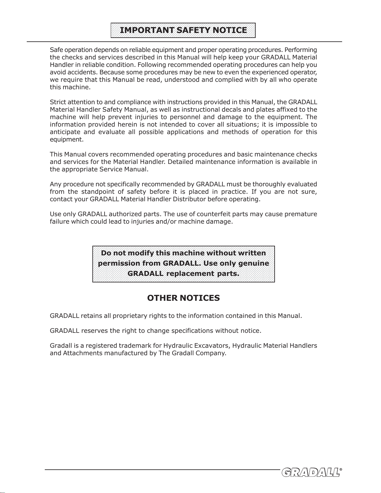
Do not modify this machine without written
permission from GRADALL. Use only genuine
GRADALL replacement parts.
OTHER NOTICES
GRADALL retains all proprietary rights to the information contained in this Manual.
GRADALL reserves the right to change specifications without notice.
Gradall is a registered trademark for Hydraulic Excavators, Hydraulic Material Handlers
and Attachments manufactured by The Gradall Company.

Form No. 20036 • G6-42A Owner/Operator Manual
REVISIONS
This page is provided so you may determine that this Manual is complete and current with respect to Gradall
Engineering Specifications.
Page Date Revision
17.1 7-22-02 Added an additional lubrication notice.
Cover 6-13-03 Revised Notes & Serial Numbers.
Intro Revised Operator Qualification section.
2.0 Revised all.
2.1 Revised all.
2.2 Replaced 9140-3525 Decal with 9150-3102 Decal.
2.3 Replaced 9147-3123 Decal with 9147-3217 Decal; added 9141-3061 Decal &
P/N’s to Angus Palm Decal.
2.4 Revised locations on 9108-3492, 9114-3288, 9114-3284, 9114-3281 &
9114-3285 Decals.
2.5 Revised location on 9114-3282 Decal.
3.0 Revised Operator’s Cab section & Figure 3-1.
3.1 Revised Warning.
3.2 Revised Service Brake description.
6.0 Revised Cold-Weather Starting Aid section.
7.0 Revised Service Brake section.
8.0 Revised Precaution & Parking Procedure sections.
12.2 Revised Load Center section; Removed Figure.
12.3 Changed Figure 12-5 to 12-4.
12.4 Changed Figure 12-6 to 12-5.
13.1 Revised Attachment Operation section.
13.8 Revised Personnel Work Platform section.
14.0 Revised Step 4; Added Figure 14-1.
16.0 Revised Moving Short Distances section.
16.1 Added Carraro Axle to title; changed all chock references to block.
16.2 Added Page for Dana Axle.
17.0 Added Figure 17-1.
17.1 Revised Art.
17.3 Changed Carraro Axle Values & Added Dana Axle Values.

TABLE OF CONTENTS
IMPORTANT SAFETY NOTICE ..................................................... inside front cover
TABLE OF CONTENTS
INTRODUCTION
General
Operator Qualifications
Orientation
Related Manuals & Decals
Models Covered
Serial Number Location
SAFETY HIGHLIGHTS ............................................................... 1.0
DECALS ................................................................................. 2.0
Decals
OPERATORS CAB..................................................................... 3.0
Cab
Control & Instrument Identification
CHECKS & SERVICES BEFORE STARTING ENGINE ........................ 4.0
WARM-UP & OPERATIONAL CHECKS ........................................... 5.0
ENGINE OPERATION ................................................................ 6.0
Starting the Engine
Cold-Weather Starting Aids
Battery-Boosted Starting
Normal Engine Operation
Stopping the Engine
BRAKE SYSTEM ....................................................................... 7.0
General
Service Brake
Park Brake
PARKING THE HANDLER ........................................................... 8.0
STEERING SYSTEM .................................................................. 9.0
DRIVE TRAIN .......................................................................... 10.0
LEVELING THE HANDLER ......................................................... 11.0
OPERATING PROCEDURE & TECHNIQUES .................................. 12.0
Hydraulic Controls
Rated Capacity Chart
ATTACHMENTS ........................................................................ 13.0
Approved Attachments
Non-Approved Attachments
Carriage/Fork Capacities
Other Attachment Capacities
Attachment Installation
Attachment Operation
OBTAINING HYDRAULIC OIL SAMPLE FOR ANALYSIS .................... 14.0
LOADING & SECURING FOR TRANSPORT .................................... 15.0
MOVING HANDLER IN EMERGENCY ............................................ 16.0
Moving Short Distances
Moving Longer Distances
MAINTENANCE SECTION .......................................................... 17.0
Nomenclature
Lubrication and Maintenance
Recommended Lubricants & Capacities
Torque Chart
Boom
INSPECTION AND MAINTENANCE LOG ....................................... 18.0
HAND SIGNALS ....................................................................... inside back cover
Form No. 20036 • G6-42A Owner/Operator Manual
General
This Manual provides important information regarding safe operating and
maintenance requirements for GRADALL Material Handlers. Refer to front cover
for specific model and serial number range.
If you have any questions regarding the material handler, contact your GRADALL
Material Handler Distributor.
Operator Qualifications
Operators of the material handler must be in good physical and mental condition,
have normal reflexes and reaction time, good vision and depth perception and
normal hearing. He must not be using medication which could impair abilities
nor be under the influence of alcohol or any other intoxicant during the work
shift.
The operator should possess a valid, applicable driver’s license and must have
completed a training course for this type of material handling equipment.
In addition, the operator must read/view, understand and comply with
instructions contained in the following material furnished with the material
handler:
• This Owner/Operator Manual
• GRADALL Material Handler Safety Manual
• All instructional decals and plates
• Any optional equipment instructions furnished
The operator must also read, understand and comply with all applicable Employer,
Industry and Governmental rules, standards and regulations.
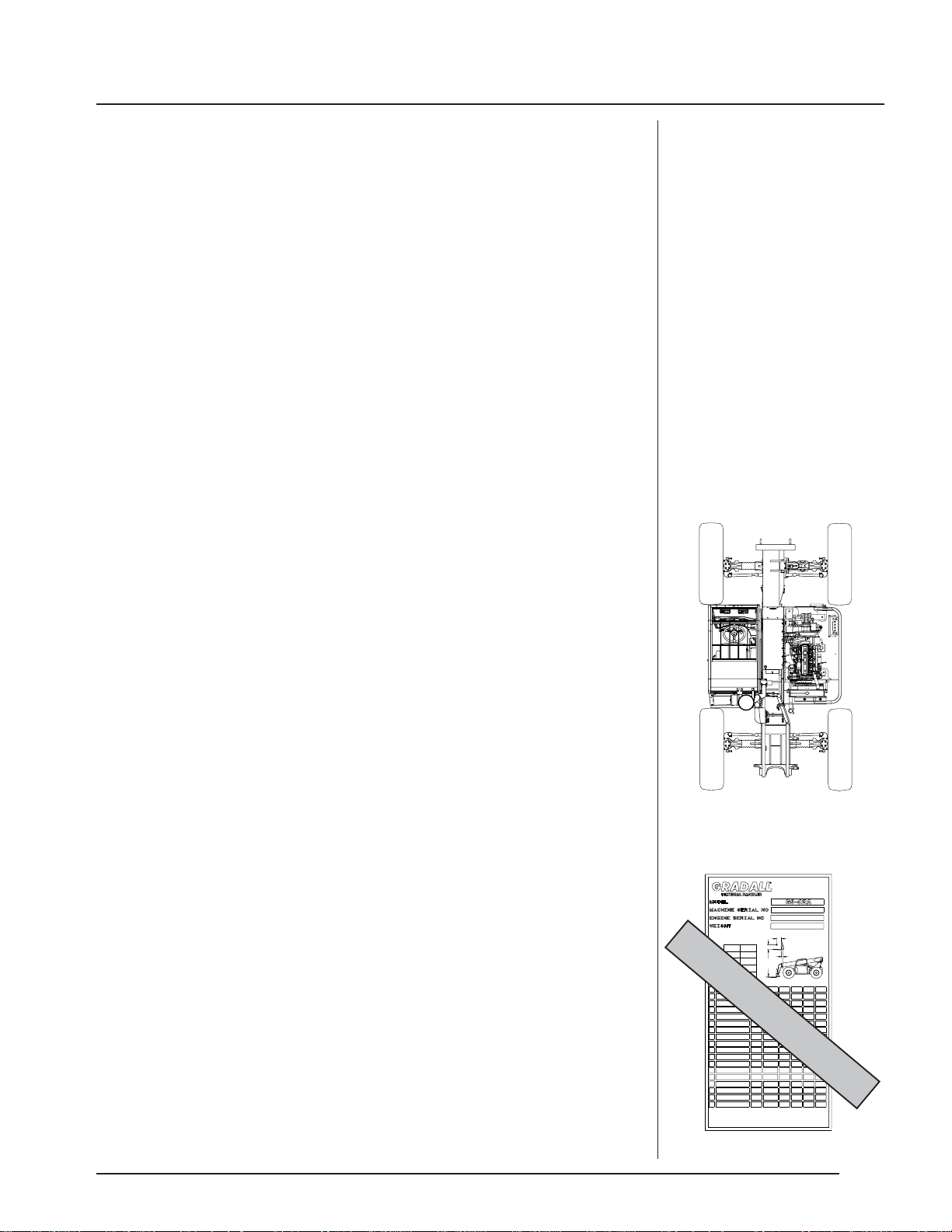
Orientation
When used to describe the location of components in the material handler, the
directions “front’”, “rear”, “right” and “left” relate to the orientation of a person
sitting in the operator’s seat. (See figure I-1)
Related Manuals & Decals
Separate publications are furnished with the material handler to provide
information concerning safety, replacement parts, maintenance procedures,
theory of operation and vendor components. Replacement manuals, decals and
instruction plates can be ordered from your GRADALL Material Handler Distributor.
Models Covered
This Manual covers basic information for Gradall Material Handlers. Detailed
information for each particular machine is in the maintenance section in the
back of this manual. Be certain to refer to proper information for your unit
and the optional equipment furnished on your machine.
Serial Number Location
Specify Model Number and Serial Number when ordering parts and when
discussing specific applications and procedures with your Distributor. The model/
serial number plate is located inside the operator’s cab, right wall.
(See figure I-2)
NOTE!
“Material handler” and handler
are used interchangeably
throughout this Manual.
Though no offense or
discrimination is intended, only
the masculine pronouns will be
used throughout the remainder
of this Manual.
NOTE!
REAR
FRONT
RIGHT
LEFT
Figure I-1
Figure I-2
INTRODUCTION
24"
24"
406 MILL AVE. S.W., NEW PHILADELPHIA, OHIO 44663
GRADALL IS A REGISTERED TRADEMARK FOR
HYDRAULIC EQUIPMENT BUILT BY THE
GRADALL CO. MANUFACTURED IN THE U.S.A.
AS RELEASED FROM FACTORY THIS TRUCK MEETS THE DESIGN SPECIFICATIONS
ESTABLISHED IN AMERICAN NATIONAL STANDARDS FOR POWERED INDUSTRIAL
TRUCKS PART III ASME B56.6b-1998.
CAP#
X1000
A
B
42'
6.6
1.0
CAPACITY WITH STANDARD
48" & 72" CARRIAGE.
(WITHOUT
ATTACHMENTS)
4.6'
B
C
A
D
20,650
20,460
24"
24"
42' 24"
C
D
ATTACHMENT
TRUCK &
ATTACHMENT
WEIGHT
24"
DCBA
6.6
20,180
CAP#
1000
9147-3131 (B)
42' 24" 24"
6.6
20,290
6.6
42' 24" 24"
24"24"42'
6.6
48" CARRIAGE
P/N 9140-5073 *
72" CARRIAGE
P/N 9140-5074 *
SHIPPED
WITH
48" SLOPE PILER
P/N 9140-5101 *
72" SLOPE PILER
P/N 9140-5079 *
2.0' 26.9'
2.0'
2.0'
2.7'
2.7'
FORKS RATED LESS THAN THE ATTACHMENT CAPACITY SHOWN ABOVE DECREASE
CAPACITY OF ATTACHMENT TO THAT OF FORKS. FORKS RATED MORE THAN
ATTACHMENT CAPACITY DO NOT INCREASE ATTACHMENT CAPACITY.
*WEIGHTS ARE BASED ON USING 2 X 4 X 48" FORKS (APPROX. 268# PER PAIR)
**BUCKET DIMENSIONS (A & D) REFER TO BUCKET LIP HEIGHT.
***TRUSS BOOM & WINCH DIMENSIONS (A & D) REFER TO HOOK CENTER.
****WEIGHT IS BASED ON SP'L SWING MAST FORKS (APPROX. 230# PER PAIR)
*****PLATFORM DIMENSIONS (A & D) REFER TO CENTER OF FLOOR.
19430 LBS
SAMPLE ONLY
In the U.S.A., the operator
must have completed a training
course meeting the OSHA
Powered Industrial Truck
Operator Training
Requirements (CFR 1910.178)
NOTE!

Read and understand all manuals and instructional material listed on cover, inside
front cover and introduction page of this Manual before starting, operating or
performing maintenance procedures on this equipment.
Regardless of previous experience operating similar equipment, the operator
must be given sufficient opportunity to practice with the handler in a safe, open
area (not hazardous to people or property) to gain operating skills and the
proper “feel” for controls and operating clearances required for safe, efficient
operation.
GRADALL Material Handlers are equipped with a right-side rearview mirror. This
mirror is intended as an operator’s aid and does not replace the requirement for
line-of-sight. Certain job site and machine conditions may require use of a signal
person to help the operator when picking, placing or transporting a load. Never
operate the handler until you know pick-up point, line of travel and landing point
are clear. Always be aware that objects in mirror are closer than they appear.
Safety Precautions
Make sure all DANGER, WARNING, CAUTION and INSTRUCTIONAL DECALS
are in place and can be read. Clean or replace decals as required.
Ensure handler is on a firm, level surface before lifting or placing load. Have
surface leveled if necessary. Unit can tip over if load is raised with handler
on a soft or uneven surface.
When traveling at high rates of speed, use two wheel front steer mode and
slow the machine prior to turning.
Do not change steer mode while the machine is traveling. Change the
steer mode only when machine is stopped.
Always look in the direction of travel. Reduce speed and be especially careful
when traveling in reverse and/or turning. Bring the machine to a complete
stop before changing the direction of travel.
Travel in reverse only at slow rates of speed.
When turning, the forks on the four wheel steer machine sweep through an arc
beyond the turn radius of the tires. Maintain adequate clearance between
the forks/load and other objects.
If load or conditions obstruct view, use a signal person when lifting, carrying
or placing a load.
Loose clothing can get caught in moving machinery and can also cause accidental
actuation of controls. Dress properly for the job.
Be alert to any unusual response to controls. If unusual response is noticed,
position handler in a safe area, lower forks to ground, apply parking brake, stop
engine and remove key from ignition switch. Tag steering wheel to forbid
operation and notify maintenance personnel.
Keep hands, gloves, shoes, control knobs and pedals clean. Slippery controls
can cause accidents. Keep a firm grip on the steering wheel when traveling.
Load capacities are based on load center being within .6m (24 inches)
from front vertical face of forks.
This symbol indicates a hazard
which may result in injury or
damage to equipment or property
if proper precautions are not
taken.
This symbol indicates a hazard
which could result in death or
serious injury if proper
precautions are not taken.
This symbol indicates an
extreme hazard which will result
in high probability of death or
serious injury if proper
precautions are not taken.
WATCH FOR THESE SYMBOLS ;
THEY CALL YOUR ATTENTION
TO SAFETY NOTICES.
SAFETY HIGHLIGHTS
1.0
Operator must be seated with
seat belt fastened, transmission
control lever in “Neutral”
position, parking brake applied
and all hydraulic controls in
“Neutral” before starting engine.
DANGER
!
WARNING
!
CAUTION
!
WARNING
!
Form No. 20036 • G6-42A Owner/Operator Manual
1.1
Release trapped pressure before disconnecting, opening or removing any
hydraulic component.
Keep all windows and mirror(s) clean. Adjust mirror(s) as
required for maximum
visibility, before and during opera
tion.
Do not increase engine speed with the transmission in forward or reverse
and the service brake pedal depressed in an attempt to get quicker hydraulic
performance. This could cause unexpected machine movement.
After bringing the material handler to a stop using the service brake, place
the directional control lever in neutral, and set the park brake prior to lifting
a load.
Allow the handler to slow down, or use the service brakes prior to down-shifting.
Do not downshift more than one gear at a time.
When traveling on downhill slopes, downshift to a lower gear and use the service
brake as necessary to maintain a slow speed. Do not shift into neutral and
coast downhill.
Never permit diesel engine to run out of fuel. Doing so can cause severe
engine damage.
DO NOT burn or drill holes in forks. Modifying any part of machine or
attachment affects it’s capacity and/or stability of machine.
Keep head, arms, hands, legs and all other body parts inside the operator’s cab
at all times.
DO NOT approach power lines, overhead or underground cables or other
power sources with any part of your material handler or load unless all
local, state/provincial and federal regulations have been met and the
appropriate utility company’s hotline has been contacted to de-energize
the lines.
Whenever leaving the cab, perform standard shut-down procedure:
Standard Shut-Down Procedure
Position the handler in a safe location, lower forks to ground, apply park
brake, move all controls to
“Neutral”, allow engine to run at low idle for 3 to 5
minutes.
Stop engine and remove ignition key. Chock wheels.
Contact The Gradall Company prior
to welding on machine.
WARNING
!
1.2
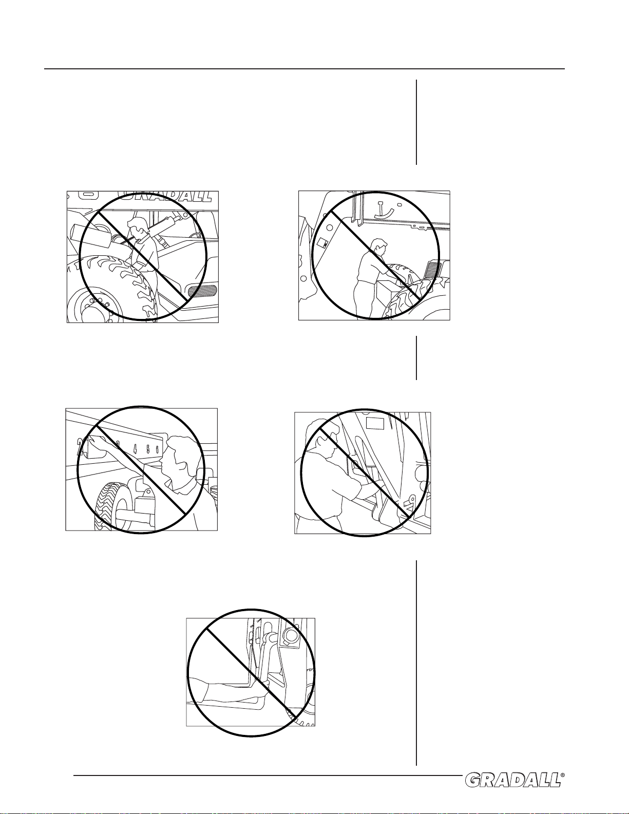
Pinch Points
Stay clear of pinch points and rotating parts on the material handler.
Getting caught in a pinch point or a moving part can cause serious
injury or death. Before performing any maintenance on machine, follow
the “STANDARD SHUT-DOWN PROCEDURE” on page 1.1.
Front & Rear Steering Axles
Boom
Boom Holes Attachment Tilt Cylinder
Carriage Forks

Form No. 20036 • G6-42A Owner/Operator Manual
THIS PAGE INTENTIONALLY LEFT BLANK.
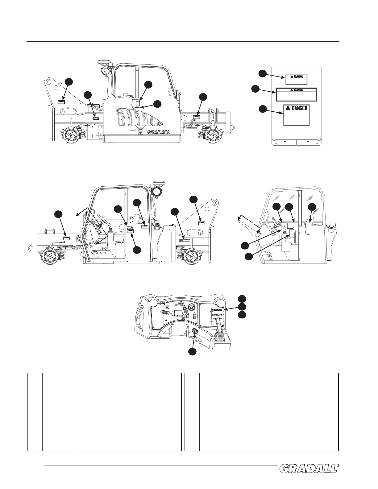
DECAL LOCATIONS
2.0
1 9114-3282 Warning Decal, Pinch P oint
2 9114-3280 Warning Decal, Exhaust System
3 9140-3569 Oil Level Decal
4 9114-3288 Hydraulic Oil Decal
5 9132-3030 Warning Decal, Capacity Chart
6 9055-3027 Warning Decal, Lifting P ersonnel
7 8060-3022 Danger Decal, High V oltage
8 7733-3027 Made in USA Decal
9 9114-3283 Warning Decal, No Riders
10 9114-3286 Warning Decal, Diesel Fuel
11 9108-3492 Oil Warning Decal
12 9055-3028 Warning Decal, Safe Operation
13 9147-3131 Serial No. & Attaching Plate
14 9150-3102 Boom Operation Decal
15 9147-3217 Service Instruction Plate
16 9140-3618 Load Chart Cover
17 9147-3139 Carriage Chart
18 9147-3162 G6-42A Capacity Chart
19 9141-3061 Ignition Decal,
(S/N 0160001283 thru Current)
1
2
3
4
1
5
6
7
1
8
10
9
1
11
5
12 13
14
15
17
16
18
19
WORK PLATFORM
6 FT. MAST
9140-3618
48" & 72"
CARRAIGE
100° SWING
CARRIAGE
B
B
9114-3283
NO RIDERS PERMITTED ON HANDLER.
OPERATOR ONLY IN MACHINE
WHILE RUNNING.
RIDERS COULD FALL OFF MACHINE
CAUSING SERIOUS INJURY OR DEATH.
9114-3286
DIESEL FUEL IS FLAMMABLE
EXTINGUISH ALL OPEN FLAME AND
SMOKING MATERIALS WHEN REFUELING
INJURY OR DEATH COULD RESULT
FROM FIRE.
9114-3282
STAY CLEAR OF PINCH POINT AREA
ANYTIME ENGINE IS RUNNING.
BEING IN PINCH POINT AREA COULD
CAUSE SERIOUS INJURY OR DEATH.
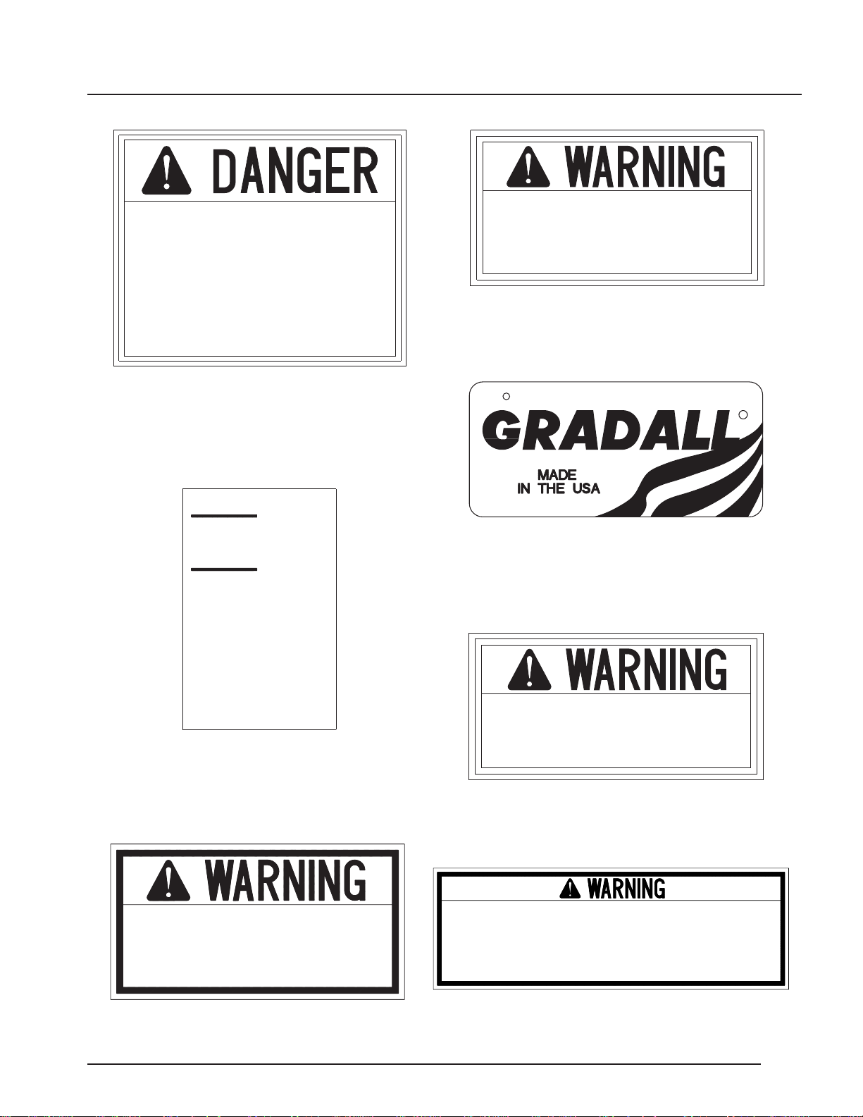
DO NOT GO NEAR LEAKS
10814B
* High pressure oil easily punctures skin causing serious injury, gangrene or death.
* If injured, seek emergency medical help. Immediate surgery is required to remove oil.
* Do not use finger or skin to check for leaks.
* Lower load or relieve hydraulic pressure before loosening fittings.
9114-3282
STAY CLEAR OF PINCH POINT AREA
ANYTIME ENGINE IS RUNNING.
BEING IN PINCH POINT AREA COULD
CAUSE SERIOUS INJURY OR DEATH.
A
A
9114-3282
STAY CLEAR OF PINCH POINT AREA
ANYTIME ENGINE IS RUNNING.
BEING IN PINCH POINT AREA COULD
CAUSE SERIOUS INJURY OR DEATH.
9114-3280
EXHAUST SYSTEMS CAN BE HOT.
KEEP AWAY FROM EXHAUST SYSTEM WHEN HOT.
HOT EXHAUST COMPONENTS CAN CAUSE
SEVERE BURNS.
ADD
FULL
9140-3569
CHECK OIL LEVEL WITH
HANDLER LEVEL AND ALL
CYLINDERS RETRACTED.
2.5 GALLON BETWEEN
ADD AND FULL MARKS
HYDRAULIC
OIL LEVEL
HYDRAULIC SYSTEM
Genuine Parts
9114-3282
STAY CLEAR OF PINCH POINT AREA
ANYTIME ENGINE IS RUNNING.
BEING IN PINCH POINT AREA COULD
CAUSE SERIOUS INJURY OR DEATH.
VIEW B-B
9132-3030
NEVER OPERATE MACHINE WITHOUT
CONSULTING PROPER CAPACITY CHART FOR THE
CARRIAGE/FORK COMBINATION BEING USED.
9055-3027 REV. A
READ AND UNDERSTAND THE FOLLOWING PRIOR TO LIFTING PERSONNEL.
WHEN LIFTING PERSONNEL USE ONLY A GRADALL MANUFACTURED PERSONNEL WORK PLATFORM.
DO NOT DRIVE MACHINE WITH PERSONNEL IN PLATFORM.
WHEN PERSONNEL ARE IN PLATFORM REMAIN SEATED IN CAB WITH PERSONNEL
IN DIRECT LINE OF SIGHT.
OPERATE CONTROLS LIGHTLY AND CAUTIOUSLY WHEN LIFTING PERSONNEL.
READ AND UNDERSTAND PERSONNEL WORK PLATFORM USER'S MANUAL BEFORE LIFTING PERSONNEL.
DO NOT USE PERSONNEL WORK PLATFORM WITHOUT THE PROPER GRADALL MATERIAL
HANDLER/PERSONNEL WORK PLATFORM CAPACITY CHART DISPLAYED IN CAB.
FAILURE TO COMPLY COULD RESULT IN SERIOUS INJURY OR DEATH.
8060-3022
AVOID HIGH VOLTAGE LINES.
IT IS UNLAWFUL TO PLACE
ANY PART OF THIS MACHINE
OR LOAD WITHIN 10 FEET
OF HIGH VOLTAGE LINES
UP TO 50,000 VOLTS.
DEATH OR INJURY MAY
RESULT FROM CONTACTING
ELECTRIC LINES.
VIEW A-A
Figure 2-1
Form No. 20036 • G6-42A Owner/Operator Manual
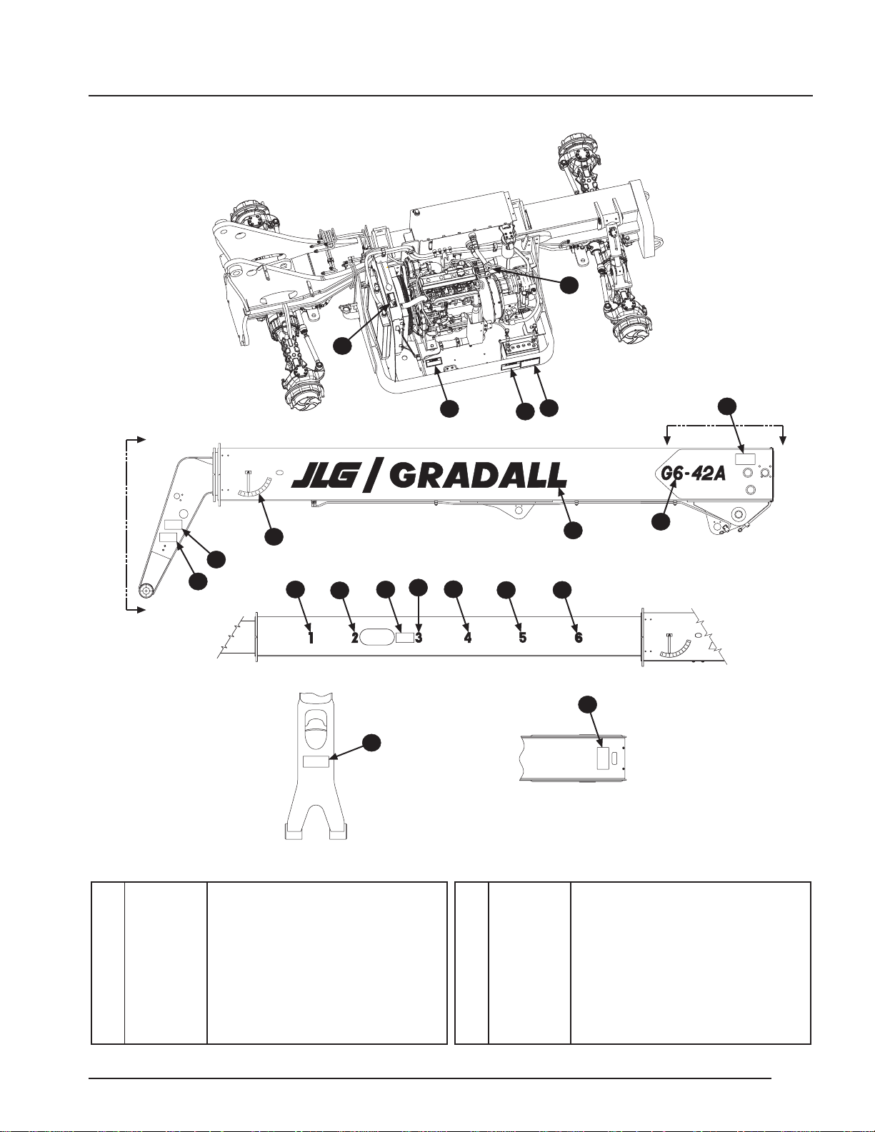
2.1
20 8060-3026 Caution Decal, Cooling System
21 9114-3281 Warning Decal, Moving Parts
22 9114-3284 Warning Decal, Battery
23 9114-3285 Instruction Decal, Jump Start
24 9140-3573 Hydraulic Fluid Decal
25 9147-3133 G6-42A Decal
26 9147-3132 Gradall Decal
27 9114-3290 Warning Decal, Attachment
28 9100-3031 Boom Angle Decal
29 8060-3037 Warning Decal, Pinch Point
30 9055-3026 Warning Decal, Lifting P ersonnel
31 9100-3016 “1” Decal
32 9100-3018 “2” Decal
33 9112-3042 “3” Decal
34 9100-3020 “4” Decal
35 9112-3044 “5” Decal
36 9116-3077 “6” Decal
C
C
D
27
1
28
29
25
26
D
31
32
33
34
35
36
29
VIEW C-C
30
VIEW D-D
29
80
6
0
-
3
0
2
6
C
O
O
L
I
N
G
S
Y
S
T
E
M
I
S
P
R
E
S
S
U
R
I
Z
E
D
.
R
E
M
O
V
E
C
A
P
S
L
O
W
L
Y
.
H
O
T
F
L
U
I
D
C
A
N
C
A
U
S
E
B
U
R
N
S
.
9
1
1
4
-
3
2
8
1
S
T
A
Y
C
L
E
A
R
O
F
M
O
V
I
N
G
P
A
R
T
S
W
H
I
L
E
E
N
G
I
N
E
I
S
R
U
N
N
I
N
G
.
M
O
V
I
N
G
P
A
R
T
S
C
A
N
C
A
U
S
E
S
E
R
I
O
U
S
I
N
J
U
R
Y
.
23
22
21
20
24
Figure 2-2
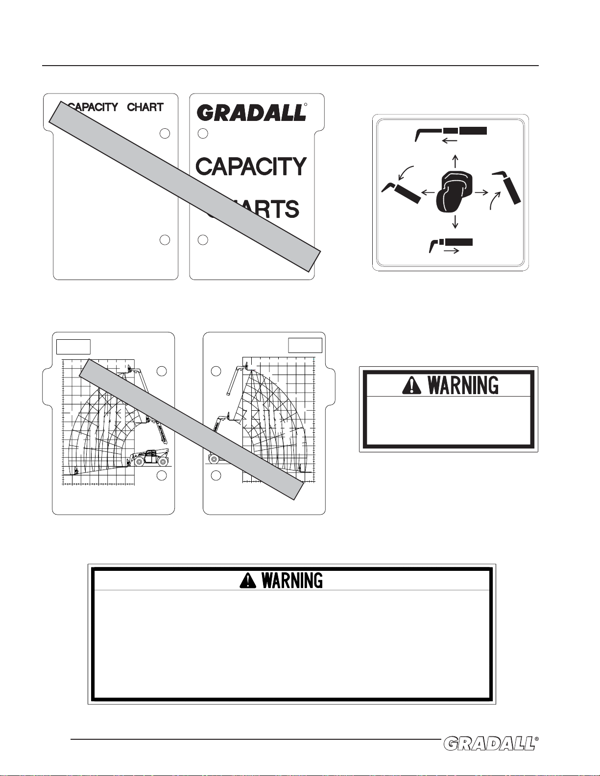
9150-3102 REV. -
DECALS
2.2
9132-3030
NEVER OPERATE MACHINE WITHOUT
CONSULTING PROPER CAPACITY CHART FOR THE
CARRIAGE/FORK COMBINATION BEING USED.
R
9140-3618
FRONT
GENERAL
NOTES
9140-3618
LEVEL GRADALL HANDLER BEFORE LIFTING ABOVE 4 FT.
USE CAPACITY CHART FOR SPECIFIC ATTACHMENT ON MACHINE.
FOR OTHER ATTACHMENTS CONSULT A GRADALL DEALER
FOR LOAD RATINGS NOT LISTED.
USE LARGEST NUMBER VISIBLE FROM THE CAB TO
DETERMINE BOOM EXTENSION.
MATCH WITH BOOM ANGLE TO DETERMINE ALLOWABLE LOAD.
FIGURES SHOWN ARE STACKING CAPACITY TRUCK LEVEL.
RATED LIFTING CAPACITIES SHOWN ARE WITH MACHINE ON A FIRM,
LEVEL SURFACE WITH UNDAMAGED, PROPERLY INFLATED TIRES.
MACHINE SPECIFICATIONS AND STABILITY ARE BASED ON RATED LIFT
CAPACITIES AT SPECIFIC BOOM ANGLES AND BOOM LENGTHS.
IF SPECIFICATIONS ARE CRITICAL, THE PROPOSED APPLICATION
SHOULD BE DISCUSSED WITH YOUR DEALER.
DO NOT EXCEED RATED LIFT CAPACITY LOADS, AS UNSTABLE AND
DANGEROUS MACHINE CONDITIONS WILL RESULT.
DO NOT TIP THE MACHINE FORWARD TO DETERMINE ALLOWABLE LOAD.
CERTAIN CARRIAGE/FORK COMBINATIONS MAY CAUSE HANDLER TO TIP
WITHOUT LOAD WHEN EXTENDED INTO "NO OPERATION" ZONE AS NOTED
ON CAPACITY CHART.
CAPACITY LIMITS FOR THIS UNIT ARE BASED IN
ACCORDANCE WITH STANDARDS LISTED ON SERIAL
NUMBER PLATE.
BACK
SAMPLE ONLY - USE CHART IN CAB
Located on dashboard
P/N 9140-3618
Located on dashboard
P/N 9147-3139
Located on right cab wall
P/N 9055-3028
Located on right cab wall
P/N 9150-3102
Located on right cab wall
and cab fender
P/N 9132-3030
8. ON INCLINES, TRAVEL WITH LOAD UP-GRADE.
9. DO NOT USE BOOM AS WALKWAY.
10. USE TWO HANDS WHEN CLIMBING ON MACHINE.
1. ONLY TRAINED AND AUTHORIZED PERSONNEL MAY
OPERATE THIS MACHINE.
2. BEFORE OPERATING, READ AND UNDERSTAND ALL CAPACITY
CHARTS, OPERATOR MANUALS AND SAFETY MANUALS. IF
MANUALS ARE NOT AVAILABLE, CONSULT AN AUTHORIZED
GRADALL DEALER. UNDERSTAND ALL CONTROLS IN CAB AND
CHECK FOR PROPER OPERATION. CLEAR LOOSE OBJECTS
OFF MACHINE AND SOUND HORN BEFORE STARTING ENGINE.
3. OPERATOR MUST BE SEATED WITH SEAT BELT FASTENED.
ASSURE FORWARD/REVERSE LEVER IS IN NEUTRAL,PARK
BRAKE APPLIED AND ALL HYDRAULIC CONTROLS ARE IN
NEUTRAL BEFORE IGNITION SWITCH IS TURNED ON.
4. DO NOT OPERATE MACHINE WITHOUT PROPER CAPACITY
CHART IN PLACE.
5. BEFORE MOVING, BE SURE OF A CLEAR PATH AND SOUND
HORN. WATCH FOR PEDESTRIANS AND OBSTRUCTIONS.
CHECK OVERHEAD AND SIDE CLEARANCES. ALWAYS LOOK
IN DIRECTION OF TRAVEL.
6. START, TURN, AND BRAKE SMOOTHLY. REDUCE TRAVEL
SPEEDS FOR TURNS, SLIPPERY, OR UNEVEN SURFACES.
AVOID RUNNING OVER LOOSE OBJECTS OR HOLES IN THE
ROADWAY SURFACE.
7. WHEN TRAVELING WITH LOAD, FULLY RETRACT BOOM AND
PLACE FORKS IN CARRY POSITION (APPROX.12" ABOVE
GROUND). TILT CARRIAGE BACK SLIGHTLY TO CRADLE
LOAD. USE EXTREME CAUTION WHEN TURNING.
11. USE ONLY A GRADALL MANUFACTURED PERSONNEL WORK
PLATFORM FOR LIFTING PERSONNEL. NO RIDERS ON MACHINE,
FORKS, LOAD, OR OTHER LIFTING ATTACHMENTS AT ANY
TIME. DO NOT USE PERSONNEL WORK PLATFORM WITHOUT THE
PROPER GRADALL MATERIAL HANDLER/PERSONNEL WORK
PLATFORM CAPACITY CHART DISPLAYED IN THE CAB. DO NOT
DRIVE MACHINE WITH PERSONNEL IN PLATFORM.
12. KEEP OTHERS AWAY FROM MACHINE WHILE OPERATING.
DO NOT STAND UNDER BOOM OR LOAD.
13. USE EXTREME CARE WHEN HANDLING LONG, HIGH, OR
WIDE LOADS. DO NOT HANDLE UNSTABLE OR LOOSELY
STACKED LOADS.
14. FORKS TO BE CENTERED UNDER LOAD AND SPACED APART
AS FAR AS POSSIBLE.
15. BEFORE ADJUSTING OR SERVICING, PLACE
FORWARD/REVERSE LEVER IN NEUTRAL, REST BOOM ON
GROUND OR SUPPORT, SET PARKING BRAKE, SHUT OFF
ENGINE AND CHOCK WHEELS.
16. BEFORE LEAVING MACHINE UNATTENDED, PLACE
FORWARD/REVERSE LEVER IN NEUTRAL, LOWER BOOM,
SET PARKING BRAKE,AND SHUT-OFF ENGINE. CHOCK
WHEELS IF MACHINE MUST PARK ON AN INCLINE.
17. LEVEL MACHINE BEFORE LIFTING ANY LOAD ABOVE 4
FEET. (IF EQUIPPED WITH FRAME LEVELING).
18. OPERATOR PROTECTION (SUCH AS HARD HATS, SAFETY
GLASSES, AND/OR HEARING PROTECTION) SHOULD BE
WORN WHEN JOB CONDITIONS WARRANT. ALWAYS USE
SEAT BELT.
19. IMPROPER USE OF MACHINE COULD RESULT IN MACHINE
TIPPING OVER. IF MACHINE STARTS TO TIP OVER, DO
NOT LEAVE OPERATORS SEAT. LEAN AWAY FROM TIP &
BRACE YOURSELF.
20. KEEP MIRROR(S) CLEAN AND PROPERLY ADJUSTED.
OBJECTS IN MIRROR ARE CLOSER THAN THEY APPEAR.
9055-3028 REV. A
FOR SAFE OPERATION OF MACHINE AND TO MINIMIZE RISK OF
SERIOUS INJURY, READ AND OBSERVE THE FOLLOWING:
48" & 72"
SLOPE PILER
9147-3139 (-)
BACK
DEDUCT 350 LBS
FROM ALL CAPACITIES
WHEN MACHINE IS
EQUIPPED WITH WINCH
MODEL
G6-42A
USE WITH: 9140-5101 48"
9140-5079 72"
SLOPE PILER CARRIAGE
RATED CAPACITY 2 FT. LOAD CENTER
600 LBS
2000 LBS
3000 LBS
4000 LBS
5000 LBS
6600 LBS
0'
4'
8'12'
16'
20'24'28'32'
-8'
-4'
0'
4'
8'
-9°
0°
10°
20°
12'
16'
20'
30°
24'
28'
32'
36'
40'
44'
48'
40°
50°
60°
70°
6
5
4
3
2
1
USE WITH:
9140-5073 48" CARRIAGE
9140-5074 72" CARRIAGE
9140-5024 WINCH (4,000 LB MAX. CAPACITY)
6600 LBS
6000 LBS
5000 LBS
4000 LBS
3000 LBS
2000 LBS
1000 LBS
9147-3139 (-)
FRONT
48" & 72"
CARRIAGES
MODEL
G6-42A
DEDUCT 350 LBS
FROM ALL CAPACITIES
WHEN MACHINE IS
EQUIPPED WITH WINCH
RATED CAPACITY 2 FT. LOAD CENTER
0°
10°
20°
30°
40°
50°
60°
70°
1
2
3
4
5
6
-9°
0'
-4'
-8'
4'
8'
12'
16'
20'
24'
28'
32'
36'
40'
44'
0'
4'
8' 12'
16'
20' 24' 28' 32'
48'
SAMPLE ONLY - USE CHART IN CAB
Form No. 20036 • G6-42A Owner/Operator Manual
24"
24"
406 MILL AVE. S.W., NEW PHILADELPHIA, OHIO 44663
GRADALL IS A REGISTERED TRADEMARK FOR
HYDRAULIC EQUIPMENT BUILT BY THE
GRADALL CO. MANUFACTURED IN THE U.S.A.
AS RELEASED FROM FACTORY THIS TRUCK MEETS THE DESIGN SPECIFICATIONS
ESTABLISHED IN AMERICAN NATIONAL STANDARDS FOR POWERED INDUSTRIAL
TRUCKS PART III ASME B56.6b-1998.
CAP#
X1000
A
B
42'
6.6
1.0
CAPACITY WITH STANDARD
48" & 72" CARRIAGE.
(WITHOUT
ATTACHMENTS)
4.6'
B
C
A
D
20,650
20,460
24"
24"
42' 24"
C
D
ATTACHMENT
TRUCK &
ATTACHMENT
WEIGHT
24"
DCBA
6.6
20,180
CAP#
1000
9147-3131 (B)
42' 24" 24"
6.6
20,290
6.6
42' 24" 24"
24"24"42'
6.6
48" CARRIAGE
P/N 9140-5073 *
72" CARRIAGE
P/N 9140-5074 *
SHIPPED
WITH
48" SLOPE PILER
P/N 9140-5101 *
72" SLOPE PILER
P/N 9140-5079 *
2.0' 26.9'
2.0'
2.0'
2.7'
2.7'
FORKS RATED LESS THAN THE ATTACHMENT CAPACITY SHOWN ABOVE DECREASE
CAPACITY OF ATTACHMENT TO THAT OF FORKS. FORKS RATED MORE THAN
ATTACHMENT CAPACITY DO NOT INCREASE ATTACHMENT CAPACITY.
*WEIGHTS ARE BASED ON USING 2 X 4 X 48" FORKS (APPROX. 268# PER PAIR)
**BUCKET DIMENSIONS (A & D) REFER TO BUCKET LIP HEIGHT.
***TRUSS BOOM & WINCH DIMENSIONS (A & D) REFER TO HOOK CENTER.
****WEIGHT IS BASED ON SP'L SWING MAST FORKS (APPROX. 230# PER PAIR)
*****PLATFORM DIMENSIONS (A & D) REFER TO CENTER OF FLOOR.
19430 LBS
SAMPLE ONLY - USE CHART IN CAB
2.3
Located on right cab wall
P/N 9147-3131
Located on right cab wall
P/N 9147-3217
Located on left side, front cab plate
P/N 9116-4094
000850
THE PROTECTION OFFERED BY THIS
ROPS WILL BE IMPAIRED IF IT HAS BEEN
SUBJECTED TO ANY MODIFICATION,
STRUCTURAL DAMAGE, OR HAS BEEN
INVOLVED IN AN OVERTURN INCIDENT.
THIS ROPS MUST BE REPLACED AFTER
A ROLL-OVER. SEAT BELTS MUST BE
WORN WHILE OPERATING VEHICLE.
GRADALL MATER 06 / 9 / 10
MAX WEIGHT : 2150
MEETS SAE : J1040 MA
MEETS ISO : 3471 (94) / 3
MEETS ANSI : B56.6 - 8.16 / P
GRADALL : 9114-3261 SERIAL : 8
Box 61 SD 57201
SAMPLE ONLY
Located on back wall, behind
operator’s seat
P/N 9147-4483 (enclosed cab)
P/N 9147-4471 (open cab)
9114-3290
ATTACHMENT MUST BE SECURED TO MACHINE.
CHECK TO ASSURE QUICK SWITCH PLUNGER
PIN IS FULLY ENGAGED AND LOCKED AFTER
ATTACHMENT CHANGE.
IF PLUNGER PIN IS NOT FULLY ENGAGED
AND LOCKED ATTACHMENT MAY FALL OFF
CAUSING SERIOUS INJURY OR DEATH.
Located on boom head
P/N 9114-3290
Diesel Engine
SERVICE INTERVALS
LUBRICATION AND MAINTENANCE
MATERIAL HANDLER
9147-3217 REV(-)
Use this chart in conjunction with the "Lubrication & Maintenance" and "Recommended
Lubricants & Capacities" sections of the Owner/Operator Manual.
Service intervals may need to be more frequent than those shown depending upon
application severity. Consult your Gradall dealer for recommendations.
It is recommended that engine oil and filter, transmission lubricant and filter,
transfer case lubricant and axle lubricant be changed after first 100 hours on
new, or rebuilt units.
LUBRICANT TYPE
OR
SPECIFICATION
Air Cleaner Element
Fuel Filter
Engine Oil Filter
Engine Oil
Coolant
Diesel Fuel
YEARLY
OR
1500 HRS
6 MO.
OR
1000 HRS
3 MO.
OR
500 HRS
EVERY 5
WKS OR
250 HRS
WEEKLY
OR
50 HRS
DAILY
OR
10 HRS
Transmission
Lubricant
Filter
Transfer Case
Lubricant
Center Section
Axle Lubricant
Planetary Hubs
Filter
Lubricant
Hydraulic System
Breather/Filter
Grease Fittings
Axles (6 Pts. Ea.)
Boom Head Pivot (2 Pts.)
Boom Pivot (2 Pts.)
Extend Chain Sheave (1 Pt.)
Drive Shafts (1 Pt. Ea.)
Cylinder Pins(13 Pts.)
Quick Switch Pin (1 Pt.)
Retract Chain Sheave (1 Pt.)
Boom
Front Bottom Bearing Pads
All Other Bearing Pads
Extend/Retract Chains
Options And Attachments
Stabilizer Cylinder (3 Pts.)
Attachment Pivots And Pins
Tires
13.00-24 12 Ply
13.00R24 Radial
15.5-25 12 Ply
Lug Nut Torque
Torque
Check
Check
Check
Check
Check
Check
Check
Check
Check
Check
Check
Check
Check
Check
Grease
Grease
Grease
Grease
Grease
Grease
Grease
Grease
Grease
Grease
Grease
Grease
Change
Change
Change
Change
Change
Change
Change
Change
Change
Change
Change
Change
SAE 15W-40 CH/CI Oil
Ethylene Glycol
No. 2 Diesel Fuel
Mobil 424
Mobil 424
Mobil 424
Mobil 424
Mobil 424
Mystik Tetrimoly
Mystik Tetrimoly
Mystik Tetrimoly
Mystik Tetrimoly
Mystik Tetrimoly
Mystik Tetrimoly
Mystik Tetrimoly
Mystik Tetrimoly
Mystik Tetrimoly
Mystik Tetrimoly
Mystik Tetrimoly
Mystik Tetrimoly
See Manual
65 PSI (448 kPa)
70 PSI (483 kPa)
58 PSI (400 kPa)
350-400 Lb-Ft (475-540 Nm)
Fill
SAMPLE ONLY - USE CHART IN CAB
Located on dash
Starting S/N 0160001283
P/N 9141-3061
2.4
8060-3026
COOLING SYSTEM
IS PRESSURIZED.
REMOVE CAP SLOWLY.
HOT FLUID CAN
CAUSE BURNS.
R
For Mobil Product Information, Call 1-800-662-4525.
HYDRAULIC SYSTEM
FILL WITH TRACTOR HYDRAULIC FLUID
or equivalent.
9114-3288
Genuine Parts
9
1
4
0
-
3
5
7
3
9114-3284
LEAD ACID BATTERIES PRODUCE FLAMABLE AND
EXPLOSIVE GASSES
WHEN CHECKING, TESTING, USING
BOOSTER BATTERY OR CHARGING BATTERIES:
* DO NOT USE SMOKING MATERIALS NEAR BATTERIES
* KEEP FLAMES AND SPARKS AWAY FROM BATTERIES
* WEAR SAFETY GLASSES
* ASSURE BATTERY IS NOT FROZEN AND ELECTROLYTE
IS AT PROPER LEVEL IN EACH CELL
FAILURE TO FOLLOW THESE INSTRUCTIONS COULD
RESULT IN SERIOUS INJURY OR DAMAGE TO THE
ELECTRICAL SYSTEM
9114-3285
WHEN JUMP STARTING MATERIAL HANDLER
* NEVER ALLOW VEHICLES TO TOUCH
* CONNECT THE POSITIVE (+) JUMPER CABLE TO
POSITIVE (+) POST OF DISCHARGED BATTERY
* CONNECT OPPOSITE END OF POSITIVE (+) JUMPER
CABLE TO POSITIVE (+) POST OF BOOSTER BATTERY
* CONNECT THE NEGATIVE (-) JUMPER CABLE TO
NEGATIVE (-) POST ON BOOSTER BATTERY
* CONNECT OPPOSITE END OF NEGATIVE (-) JUMPER
CABLE TO GROUND POINT ON MACHINE AWAY FROM
DISCHARGED BATTERY
* FOLLOW STANDARD STARTING PROCEDURES
* REMOVE CABLES IN REVERSE ORDER AFTER MACHINE
HAS STARTED
JUMP STARTING INSTRUCTIONS
9114-3281
STAY CLEAR OF MOVING PARTS
WHILE ENGINE IS RUNNING.
MOVING PARTS CAN CAUSE
SERIOUS INJURY.
Located on frame beside main control valve
P/N 9108-3492
Located on radiator
P/N 8060-3026
Located on hydraulic fill cap
P/N 9140-3573
Located on frame below engine cover
P/N 9114-3284
Located on frame below engine cover
P/N 9114-3285
Located on hydraulic reservoir
P/N 9114-3288
Located in engine compartment
P/N 9114-3281
DECALS
Form No. 20036 • G6-42A Owner/Operator Manual
2.5
8060-3022
AVOID HIGH VOLTAGE LINES.
IT IS UNLAWFUL TO PLACE
ANY PART OF THIS MACHINE
OR LOAD WITHIN 10 FEET
OF HIGH VOLTAGE LINES
UP TO 50,000 VOLTS.
DEATH OR INJURY MAY
RESULT FROM CONTACTING
ELECTRIC LINES.
ADD
CHECK OIL LEVEL WITH
HANDLER LEVEL AND ALL
CYLINDERS RETRACTED.
2.5 GALLON BETWEEN
ADD AND FULL MARKS
FULL
HYDRAULIC
OIL LEVEL
9140-3569
R
7733-3027
9114-3286
DIESEL FUEL IS FLAMMABLE
EXTINGUISH ALL OPEN FLAME AND
SMOKING MATERIALS WHEN REFUELING
INJURY OR DEATH COULD RESULT
FROM FIRE.
9114-3283
NO RIDERS PERMITTED ON HANDLER.
OPERATOR ONLY IN MACHINE
WHILE RUNNING.
RIDERS COULD FALL OFF MACHINE
CAUSING SERIOUS INJURY OR DEATH.
9114-3282
STAY CLEAR OF PINCH POINT AREA
ANYTIME ENGINE IS RUNNING.
BEING IN PINCH POINT AREA COULD
CAUSE SERIOUS INJURY OR DEATH.
Located on cab fender
P/N 8060-3022
Located on hydraulic reservoir
P/N 9140-3569
Located on both sides of frame
near axles and boom head
P/N 9114-3282
Located on left cab wall
P/N 9114-3283
Located on left cab wall
P/N 7733-3027
Located on left cab wall
P/N 9114-3286
Located on mud guard
P/N 9055-3027
9055-3027 REV. A
READ AND UNDERSTAND THE FOLLOWING PRIOR TO LIFTING PERSONNEL.
WHEN LIFTING PERSONNEL USE ONLY A GRADALL MANUFACTURED PERSONNEL WORK PLATFORM.
DO NOT DRIVE MACHINE WITH PERSONNEL IN PLATFORM.
WHEN PERSONNEL ARE IN PLATFORM REMAIN SEATED IN CAB WITH PERSONNEL
IN DIRECT LINE OF SIGHT.
OPERATE CONTROLS LIGHTLY AND CAUTIOUSLY WHEN LIFTING PERSONNEL.
READ AND UNDERSTAND PERSONNEL WORK PLATFORM USER'S MANUAL BEFORE LIFTING PERSONNEL.
DO NOT USE PERSONNEL WORK PLATFORM WITHOUT THE PROPER GRADALL MATERIAL
HANDLER/PERSONNEL WORK PLATFORM CAPACITY CHART DISPLAYED IN CAB.
FAILURE TO COMPLY COULD RESULT IN SERIOUS INJURY OR DEATH.
2.6
9114-3280
EXHAUST SYSTEMS CAN BE HOT.
KEEP AWAY FROM EXHAUST SYSTEM WHEN HOT.
HOT EXHAUST COMPONENTS CAN CAUSE
SEVERE BURNS.
8060-3037-A
PINCH POINT
KEEP OUT
REACHING INTO BOOM
HOLES AND OTHER PINCH
POINTS CAN CAUSE
SERIOUS INJURY
OR DEATH.
Located on right rear frame
P/N 9114-3280
Located on left side of boom
P/N 9100-3031
Located on boom
P/N 8060-3037
406 MILL AVE. S.W. NEW PHILADELPHIA, OHIO MADE IN U. S. A.
THE CAPACITY OF FORKLIFT, ATTACHMENT AND FORK
COMBINATION MAY BE LESS THAN THE CAPACITY SHOWN
ON ATTACHMENT - CONSULT FORKLIFT NAMEPLATE
AND ALSO INSURE FORKS ARE OF PROPER SIZE.
9015-3001
ATTACHMENT
SERIAL NUMBER
WEIGHT
CAPACITY
HYD. PRESSURE
Located on attachment
P/N 9015-3001
Located on boom head & personnel
work platform
P/N 9055-3026
9055-3026 REV. A
READ AND UNDERSTAND THE FOLLOWING PRIOR TO LIFTING PERSONNEL.
WHEN LIFTING PERSONNEL USE ONLY A GRADALL MANUFACTURED
PERSONNEL WORK PLATFORM.
ALL PERSONNEL IN PLATFORM MUST WEAR A FULL BODY HARNESS WITH
LANYARD ATTACHED TO A DESIGNATED ANCHORAGE POINT.
READ AND UNDERSTAND PERSONNEL WORK PLATFORM USER'S MANUAL
BEFORE OCCUPYING PERSONNEL WORK PLATFORM.
FAILURE TO COMPLY COULD RESULT IN SERIOUS INJURY OR DEATH.
Located on Personnel
work platform
P/N 9055-3031
9055-3031 REV. A
MAXIMUM OCCUPANCY THREE (3) PEOPLE.
DO NOT USE PERSONNEL WORK PLATFORM
WITHOUT THE PROPER GRADALL MATERIAL
HANDLER/PERSONNEL WORK PLATFORM
CAPACITY CHART DISPLAYED IN CAB.
FAILURE TO COMPLY COULD RESULT IN
SERIOUS INJURY OR DEATH.
Located on work platform
P/N 9055-3032
ATTACH LANYARD HERE
9055-3032
Located on Personnel Work Platform
P/N 9055-3033
406 MILL AVE. S.W. NEW PHILADELPHIA, OHIO MADE IN U. S. A.
DO NOT USE PERSONNEL WORK PLATFORM WITHOUT THE
PROPER GRADALL MATERIAL HANDLER/PERSONNEL WORK
PLATFORM CAPACITY CHART DISPLAYED IN CAB.
9055-3033
ATTACHMENT
SERIAL NUMBER
WEIGHT
CAPACITY
HYD. PRESSURE
DECALS
Loading...