


G12-55A
Table of contents
 Loading...
An Oshkosh Corporation Company
Illustrated Parts Manual
Models
G10-55A
G12-55A
S/N 0160045636 & After including
0160045082, 0160045094,
0160045209, 0160045295,
0160045296 & 0160045449
31200728
Revised
March 4, 2014


May 1, 2012 - A - Original Issue of Manual
January 4, 2013 - B - Revised Manual
January 29, 2013 - C - Revised Manual
April 3, 2013 - D - Revised Manual
August 2, 2013 - E - Revised Manual
January 10, 2014 - F - Revised Manual
March 4, 2014 - G - Revised Manual
EFFECTIVITY PAGE
31200728 G10-55A, G12-55A i

EFFECTIVITY PAGE
G10-55A, G12-55A 31200728ii
Machine Configuration
OY2700
1
ULTRA LOW
SULFUR DIESEL
FUEL ONLY
S < 15 mg/kg
1001125387 A
REAR VIEW OF CAB
Two configurations of each machine are included in this manual. Determine if machine is equipped with Ultra Low Sulfur Fuel Decal (1).
If equipped with the Ultra Low Sulfur decal, all specific references to this machine configuration will be referred to as Ultra Low Sulfur
(ULS) from this point forward.
If not equipped with the Ultra Low Sulfur decal, all specific references to this machine configuration will be referred to as Low Sulfur (LS)
from this point forward.
1

General Information
1. MACHINE IDENTIFICATION
Machines are identified by model & in some cases a combination of model, serial number (S/N) or regional standard (CE, AUS,
ANSI). Components may also be identified by S/N or manufacturer. Common components that may be identified by these
characteristics are attachments, engine, transmission & hydraulic components.
2. PARTS MANUAL ORGANIZATION
Product information in this manual is organized under section titles. Frame & Attaching Parts, Drive Train & Electrical are a few
examples. Each section is organized by Figure & page number. The information within the Figure is then organized by item number,
part number, description & corresponding illustration(s).
3. TABLE OF CONTENTS
A table of contents (TOC) is found toward the beginning of the manual. Figure number, description & page number are provided for
quick reference to the page containing the related information.
4. RECOMMENDED SPARE PARTS
The Recommended Spare Parts, located near the end of the manual, references most frequently used maintenance parts.
5. PART NUMBER INDEX
A numerical index listing all part numbers & the corresponding page number(s) appears at the back of the manual.
6. NON-SERVICED PARTS
In some instances it is necessary to display non-serviced parts, assemblies or installations. In the case of assemblies & installations
there will be a Ref in the Qty column & a note after the item description stating what is available for service within. In the case of
parts that are not available for service within assemblies or components there will be a NSS (Not Sold Separately) listed in the part
number column of the manual.
7. PARTS LIST ITEM NUMBERS
Numbers shown in the Item column correspond to numbers used in the associated illustration(s). Item numbers which are missing
from sequence & are not shown in the illustration(s) are not used on that page.
8. INDENTED PART DESCRIPTION
An indented part description is included in the item under which it is indented.
9. ABBREVIATIONS & SYMBOLS
AC.................................................................... Air Conditioning
ANSI ............................. American National Standards Institute
AR..........................................................................As Required
ASME.................... American Society of Mechanical Engineers
ASSY ......................................................................... Assembly
AUS..............................................................................Australia
AUX..............................................................................Auxiliary
CE............................................................European Conformity
DIA..............................................................................Diameter
EURO.........................................................................European
FT ...................................................................................... Foot
GA...................................................................................Gauge
GR ...................................................................................Grade
HD.....................................................................................Head
HYD ............................................................................Hydraulic
ID ..................................................................... Inside Diameter
IN ........................................................................................Inch
ISO............................. International Organization for Standards
ITSDF ..... Industrial Truck Standards Development Foundation
KG............................................................................... Kilogram
kW.................................................................................Kilowatt
10. ILLUSTRATION REFERENCE LETTERS
When necessary, illustrations may contain reference letters that are intended to track information from one point to another in the
illustration such as harnesses & hoses or any other information that has been separated in the illustration.
LB ....................................................................................Pound
LH.............................................................................. Left Hand
LS ............................................................................. Low Sulfur
MAX........................................................................... Maximum
MM .............................................................................Millimeter
N....................................................................................Newton
NA ...................................................................... Not Applicable
NLA ...........................................................No Longer Available
NSS ........................................................... Not Sold Separately
OD ................................................................. Outside Diameter
OZ .................................................................................. Ounce
P/N ........................................................................Part Number
QTY ..............................................................................Quantity
REF ...........................................................................Reference
REQ............................................................................ Required
RH ...........................................................................Right Hand
S/N ..................................................................... Serial Number
SAE ....................................... Society of Automotive Engineers
STD ............................................................................ Standard
ULS ..................................................................Ultra Low Sulfur
V ..........................................................................................Volt
Note: Due to continuous product improvements, JLG Industries, Inc. reserves the right to make specification changes without prior
notification. Contact JLG Industries, Inc. for updated information.
2
2
7
1
8
9
9
6
7
1
3

This Page Intentionally Left Blank
4

TABLE OF CONTENTS
FIGURE NO. TITLE PAGE NO.
SECTION 1 –
FRAME & ATTACHING PARTS . . . . . . . . . . . . . . . . . . . . . . . . . . . . . . . . . . . . . . . . . . . . . . . . 1-1
1-1 Frame & Attaching Parts . . . . . . . . . . . . . . . . . . . . . . . . . . . . . . . . . . . . . . . . . . . . . . . . . . . . . . . 1-2
1-2 Covers . . . . . . . . . . . . . . . . . . . . . . . . . . . . . . . . . . . . . . . . . . . . . . . . . . . . . . . . . . . . . . . . . . . . . 1-4
1-3 Outrigger Installation . . . . . . . . . . . . . . . . . . . . . . . . . . . . . . . . . . . . . . . . . . . . . . . . . . . . . . . . . . 1-8
1-4 Pintle Hook . . . . . . . . . . . . . . . . . . . . . . . . . . . . . . . . . . . . . . . . . . . . . . . . . . . . . . . . . . . . . . . . . . 1-10
SECTION 2 –
BOOM . . . . . . . . . . . . . . . . . . . . . . . . . . . . . . . . . . . . . . . . . . . . . . . . . . . . . . . . . . . . . . . . . . . . 2-1
2-1 Boom Installation . . . . . . . . . . . . . . . . . . . . . . . . . . . . . . . . . . . . . . . . . . . . . . . . . . . . . . . . . . . . . 2-2
2-2 First Boom Section . . . . . . . . . . . . . . . . . . . . . . . . . . . . . . . . . . . . . . . . . . . . . . . . . . . . . . . . . . . . 2-4
2-3 Second Boom Section . . . . . . . . . . . . . . . . . . . . . . . . . . . . . . . . . . . . . . . . . . . . . . . . . . . . . . . . . 2-8
2-4 Third Boom Section . . . . . . . . . . . . . . . . . . . . . . . . . . . . . . . . . . . . . . . . . . . . . . . . . . . . . . . . . . . 2-12
2-5 Fourth Boom Section . . . . . . . . . . . . . . . . . . . . . . . . . . . . . . . . . . . . . . . . . . . . . . . . . . . . . . . . . . 2-16
2-6 Extend Chains . . . . . . . . . . . . . . . . . . . . . . . . . . . . . . . . . . . . . . . . . . . . . . . . . . . . . . . . . . . . . . . 2-20
2-7 Retract Chains . . . . . . . . . . . . . . . . . . . . . . . . . . . . . . . . . . . . . . . . . . . . . . . . . . . . . . . . . . . . . . . 2-24
2-8 Manual Quick Attach . . . . . . . . . . . . . . . . . . . . . . . . . . . . . . . . . . . . . . . . . . . . . . . . . . . . . . . . . . 2-30
SECTION 3 –
ATTACHMENTS . . . . . . . . . . . . . . . . . . . . . . . . . . . . . . . . . . . . . . . . . . . . . . . . . . . . . . . . . . . . 3-1
3-1 Standard Carriage . . . . . . . . . . . . . . . . . . . . . . . . . . . . . . . . . . . . . . . . . . . . . . . . . . . . . . . . . . . . 3-2
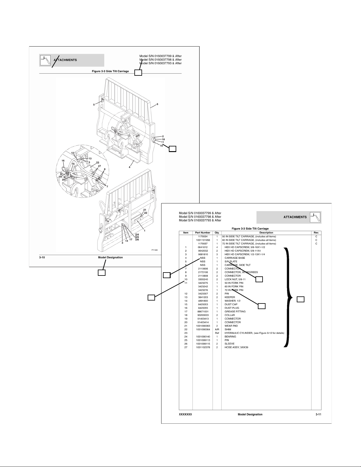
3-2 Side Tilt Carriage . . . . . . . . . . . . . . . . . . . . . . . . . . . . . . . . . . . . . . . . . . . . . . . . . . . . . . . . . . . . . 3-6
3-3 50 In Side Shift Carriage . . . . . . . . . . . . . . . . . . . . . . . . . . . . . . . . . . . . . . . . . . . . . . . . . . . . . . . 3-8
3-4 Dual Fork Positioning Carriage . . . . . . . . . . . . . . . . . . . . . . . . . . . . . . . . . . . . . . . . . . . . . . . . . . 3-10
3-5 90 Degree Swing Carriage . . . . . . . . . . . . . . . . . . . . . . . . . . . . . . . . . . . . . . . . . . . . . . . . . . . . . . 3-12
3-6 180 Degree Swing Carriage . . . . . . . . . . . . . . . . . . . . . . . . . . . . . . . . . . . . . . . . . . . . . . . . . . . . . 3-14
3-7 Sheet Handler Carriage . . . . . . . . . . . . . . . . . . . . . . . . . . . . . . . . . . . . . . . . . . . . . . . . . . . . . . . . 3-18
3-8 Forks & Attaching Parts . . . . . . . . . . . . . . . . . . . . . . . . . . . . . . . . . . . . . . . . . . . . . . . . . . . . . . . . 3-20
3-9 Fork Mounted Platform . . . . . . . . . . . . . . . . . . . . . . . . . . . . . . . . . . . . . . . . . . . . . . . . . . . . . . . . . 3-22
3-10 Fork Mounted Hook . . . . . . . . . . . . . . . . . . . . . . . . . . . . . . . . . . . . . . . . . . . . . . . . . . . . . . . . . . . 3-24
3-11 General Purpose Bucket . . . . . . . . . . . . . . . . . . . . . . . . . . . . . . . . . . . . . . . . . . . . . . . . . . . . . . . 3-26
3-12 Grapple Bucket . . . . . . . . . . . . . . . . . . . . . . . . . . . . . . . . . . . . . . . . . . . . . . . . . . . . . . . . . . . . . . . 3-28
3-13 Truss Boom . . . . . . . . . . . . . . . . . . . . . . . . . . . . . . . . . . . . . . . . . . . . . . . . . . . . . . . . . . . . . . . . . 3-30
3-14 Truss Boom with Winch . . . . . . . . . . . . . . . . . . . . . . . . . . . . . . . . . . . . . . . . . . . . . . . . . . . . . . . . 3-32
3-15 8 Foot Standard Mast . . . . . . . . . . . . . . . . . . . . . . . . . . . . . . . . . . . . . . . . . . . . . . . . . . . . . . . . . . 3-34
3-16 8 Ft Side Tilt Electric Mast . . . . . . . . . . . . . . . . . . . . . . . . . . . . . . . . . . . . . . . . . . . . . . . . . . . . . . 3-38
SECTION 4 –
ENGINE & ATTACHING PARTS . . . . . . . . . . . . . . . . . . . . . . . . . . . . . . . . . . . . . . . . . . . . . . . 4-1
4-1 Engine Installation . . . . . . . . . . . . . . . . . . . . . . . . . . . . . . . . . . . . . . . . . . . . . . . . . . . . . . . . . . . . 4-2
4-2 Engine . . . . . . . . . . . . . . . . . . . . . . . . . . . . . . . . . . . . . . . . . . . . . . . . . . . . . . . . . . . . . . . . . . . . . 4-4
4-3 Fuel Tank & Lines . . . . . . . . . . . . . . . . . . . . . . . . . . . . . . . . . . . . . . . . . . . . . . . . . . . . . . . . . . . . 4-8
4-4 Radiator Installation . . . . . . . . . . . . . . . . . . . . . . . . . . . . . . . . . . . . . . . . . . . . . . . . . . . . . . . . . . . 4-10
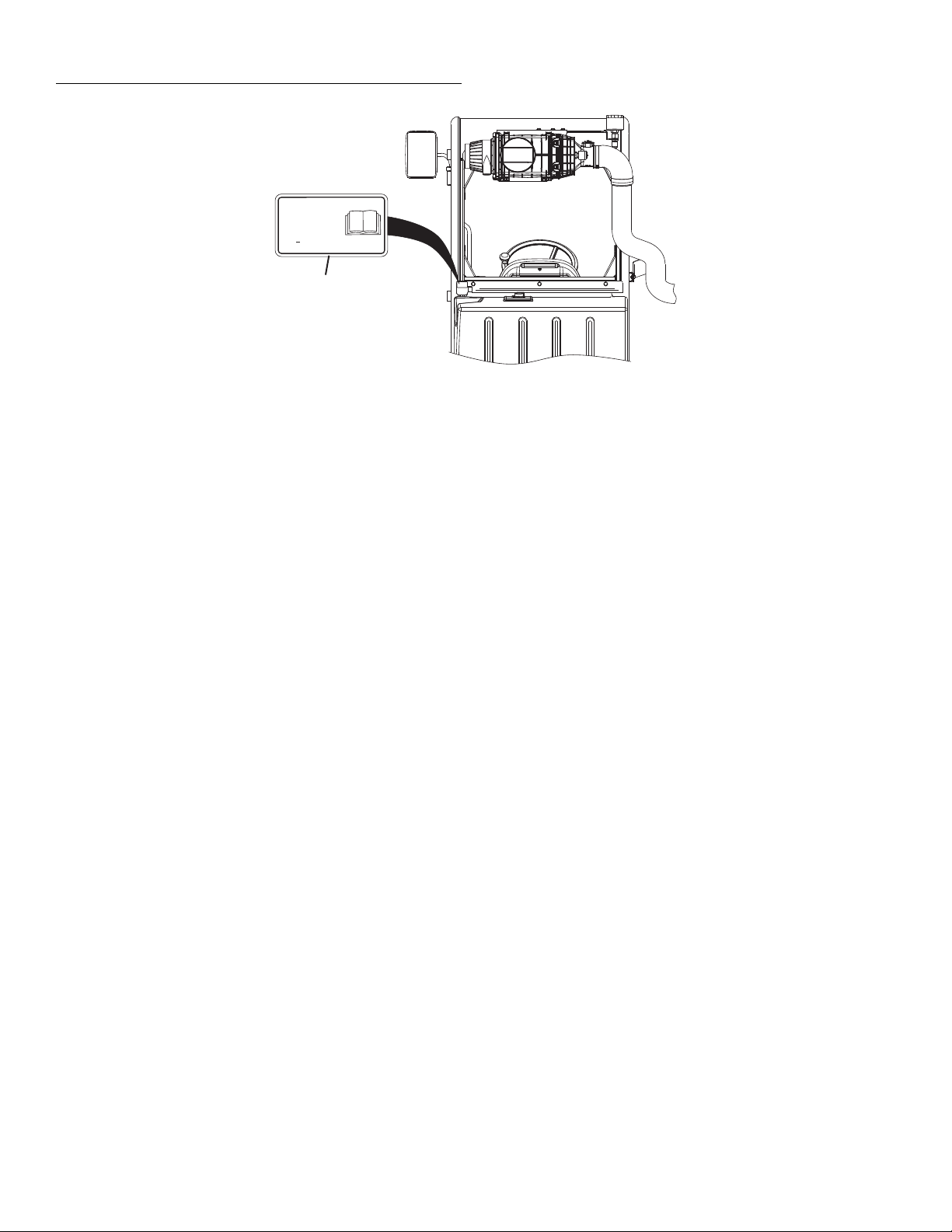
4-5 Air Cleaner Installation . . . . . . . . . . . . . . . . . . . . . . . . . . . . . . . . . . . . . . . . . . . . . . . . . . . . . . . . . 4-14
31200728 G10-55A, G12-55A 5

TABLE OF CONTENTS
FIGURE NO. TITLE PAGE NO.
4-6 Exhaust Installation . . . . . . . . . . . . . . . . . . . . . . . . . . . . . . . . . . . . . . . . . . . . . . . . . . . . . . . . . . . 4-18
SECTION 5 –
DRIVE TRAIN . . . . . . . . . . . . . . . . . . . . . . . . . . . . . . . . . . . . . . . . . . . . . . . . . . . . . . . . . . . . . . . 5-1
5-1 Drivetrain Components . . . . . . . . . . . . . . . . . . . . . . . . . . . . . . . . . . . . . . . . . . . . . . . . . . . . . . . . 5-2
5-2 Front Axle . . . . . . . . . . . . . . . . . . . . . . . . . . . . . . . . . . . . . . . . . . . . . . . . . . . . . . . . . . . . . . . . . . . 5-10
5-3 Front Axle - Central Housing & Steering . . . . . . . . . . . . . . . . . . . . . . . . . . . . . . . . . . . . . . . . . . . 5-12
5-4 Front Axle - Differential . . . . . . . . . . . . . . . . . . . . . . . . . . . . . . . . . . . . . . . . . . . . . . . . . . . . . . . . 5-16
5-5 Front Axle - Hub Reduction . . . . . . . . . . . . . . . . . . . . . . . . . . . . . . . . . . . . . . . . . . . . . . . . . . . . . 5-20
5-6 Front Axle - Brakes . . . . . . . . . . . . . . . . . . . . . . . . . . . . . . . . . . . . . . . . . . . . . . . . . . . . . . . . . . . 5-28
5-7 Rear Axle . . . . . . . . . . . . . . . . . . . . . . . . . . . . . . . . . . . . . . . . . . . . . . . . . . . . . . . . . . . . . . . . . . . 5-32
5-8 Rear Axle - Central Housing & Steering . . . . . . . . . . . . . . . . . . . . . . . . . . . . . . . . . . . . . . . . . . . . 5-34
5-9 Rear Axle - Differential . . . . . . . . . . . . . . . . . . . . . . . . . . . . . . . . . . . . . . . . . . . . . . . . . . . . . . . . . 5-38
5-10 Rear Axle - Hub Reduction . . . . . . . . . . . . . . . . . . . . . . . . . . . . . . . . . . . . . . . . . . . . . . . . . . . . . 5-42
5-11 Rear Axle - Brakes . . . . . . . . . . . . . . . . . . . . . . . . . . . . . . . . . . . . . . . . . . . . . . . . . . . . . . . . . . . . 5-48
5-12 Transmission . . . . . . . . . . . . . . . . . . . . . . . . . . . . . . . . . . . . . . . . . . . . . . . . . . . . . . . . . . . . . . . . 5-52
5-13 Transmission - Converter & Input . . . . . . . . . . . . . . . . . . . . . . . . . . . . . . . . . . . . . . . . . . . . . . . . 5-54
5-14 Transmission - Gearbox Housing . . . . . . . . . . . . . . . . . . . . . . . . . . . . . . . . . . . . . . . . . . . . . . . . . 5-56
5-15 Transmission - Forward Gear Group . . . . . . . . . . . . . . . . . . . . . . . . . . . . . . . . . . . . . . . . . . . . . . 5-58
5-16 Transmission - Reverse Gear Group . . . . . . . . . . . . . . . . . . . . . . . . . . . . . . . . . . . . . . . . . . . . . . 5-60
5-17 Transmission - 1st Shaft Group . . . . . . . . . . . . . . . . . . . . . . . . . . . . . . . . . . . . . . . . . . . . . . . . . . 5-62
5-18 Transmission - 2nd Shaft Group . . . . . . . . . . . . . . . . . . . . . . . . . . . . . . . . . . . . . . . . . . . . . . . . . 5-64
5-19 Transmission - 3rd Shaft Group . . . . . . . . . . . . . . . . . . . . . . . . . . . . . . . . . . . . . . . . . . . . . . . . . . 5-66
5-20 Transmission - 4th Shaft Group . . . . . . . . . . . . . . . . . . . . . . . . . . . . . . . . . . . . . . . . . . . . . . . . . . 5-68
5-21 Transmission - Power Take-Off . . . . . . . . . . . . . . . . . . . . . . . . . . . . . . . . . . . . . . . . . . . . . . . . . . 5-70
5-22 Transmission - Control Unit & Pressure Regulator . . . . . . . . . . . . . . . . . . . . . . . . . . . . . . . . . . . 5-72
5-23 Transmission - Gearshift System . . . . . . . . . . . . . . . . . . . . . . . . . . . . . . . . . . . . . . . . . . . . . . . . . 5-74
5-24 Transmission - Oil Pump, Filter & Dipstick . . . . . . . . . . . . . . . . . . . . . . . . . . . . . . . . . . . . . . . . . . 5-76
5-25 Transmission - Transfer Box . . . . . . . . . . . . . . . . . . . . . . . . . . . . . . . . . . . . . . . . . . . . . . . . . . . . 5-78
5-26 Wheel Assembly . . . . . . . . . . . . . . . . . . . . . . . . . . . . . . . . . . . . . . . . . . . . . . . . . . . . . . . . . . . . . 5-80
5-27 Fender Installation . . . . . . . . . . . . . . . . . . . . . . . . . . . . . . . . . . . . . . . . . . . . . . . . . . . . . . . . . . . . 5-82
SECTION 6 –
CAB . . . . . . . . . . . . . . . . . . . . . . . . . . . . . . . . . . . . . . . . . . . . . . . . . . . . . . . . . . . . . . . . . . . . . . 6-1
6-1 Cab Installation . . . . . . . . . . . . . . . . . . . . . . . . . . . . . . . . . . . . . . . . . . . . . . . . . . . . . . . . . . . . . . 6-2
6-2 Cab Assembly . . . . . . . . . . . . . . . . . . . . . . . . . . . . . . . . . . . . . . . . . . . . . . . . . . . . . . . . . . . . . . . 6-6
6-3 Cab Door . . . . . . . . . . . . . . . . . . . . . . . . . . . . . . . . . . . . . . . . . . . . . . . . . . . . . . . . . . . . . . . . . . . 6-10
6-4 Cab Interior . . . . . . . . . . . . . . . . . . . . . . . . . . . . . . . . . . . . . . . . . . . . . . . . . . . . . . . . . . . . . . . . . 6-12
6-5 Wipers . . . . . . . . . . . . . . . . . . . . . . . . . . . . . . . . . . . . . . . . . . . . . . . . . . . . . . . . . . . . . . . . . . . . . 6-14
6-6 Seats . . . . . . . . . . . . . . . . . . . . . . . . . . . . . . . . . . . . . . . . . . . . . . . . . . . . . . . . . . . . . . . . . . . . . . 6-16
6-7 Heater Installation . . . . . . . . . . . . . . . . . . . . . . . . . . . . . . . . . . . . . . . . . . . . . . . . . . . . . . . . . . . . 6-18
6-8 Air Conditioning Installation . . . . . . . . . . . . . . . . . . . . . . . . . . . . . . . . . . . . . . . . . . . . . . . . . . . . . 6-22
G10-55A, G12-55A 312007286

TABLE OF CONTENTS
FIGURE NO. TITLE PAGE NO.
SECTION 7 –
CONTROLS . . . . . . . . . . . . . . . . . . . . . . . . . . . . . . . . . . . . . . . . . . . . . . . . . . . . . . . . . . . . . . . . 7-1
7-1 Brake . . . . . . . . . . . . . . . . . . . . . . . . . . . . . . . . . . . . . . . . . . . . . . . . . . . . . . . . . . . . . . . . . . . . . . 7-2
7-2 Accelerator . . . . . . . . . . . . . . . . . . . . . . . . . . . . . . . . . . . . . . . . . . . . . . . . . . . . . . . . . . . . . . . . . . 7-4
7-3 Steering Column . . . . . . . . . . . . . . . . . . . . . . . . . . . . . . . . . . . . . . . . . . . . . . . . . . . . . . . . . . . . . . 7-6
7-4 Boom Joystick . . . . . . . . . . . . . . . . . . . . . . . . . . . . . . . . . . . . . . . . . . . . . . . . . . . . . . . . . . . . . . . 7-8
7-5 Outrigger & Frame Level/Auxiliary Controller . . . . . . . . . . . . . . . . . . . . . . . . . . . . . . . . . . . . . . . . 7-10
SECTION 8 –
HYDRAULIC CIRCUITS . . . . . . . . . . . . . . . . . . . . . . . . . . . . . . . . . . . . . . . . . . . . . . . . . . . . . . 8-1
8-1 Supply Circuit . . . . . . . . . . . . . . . . . . . . . . . . . . . . . . . . . . . . . . . . . . . . . . . . . . . . . . . . . . . . . . . . 8-2
8-2 Dump Circuit . . . . . . . . . . . . . . . . . . . . . . . . . . . . . . . . . . . . . . . . . . . . . . . . . . . . . . . . . . . . . . . . . 8-6
8-3 Steer Select Circuit . . . . . . . . . . . . . . . . . . . . . . . . . . . . . . . . . . . . . . . . . . . . . . . . . . . . . . . . . . . . 8-8
8-4 Service Brake Circuit . . . . . . . . . . . . . . . . . . . . . . . . . . . . . . . . . . . . . . . . . . . . . . . . . . . . . . . . . . 8-10
8-5 Boom Joystick Circuit . . . . . . . . . . . . . . . . . . . . . . . . . . . . . . . . . . . . . . . . . . . . . . . . . . . . . . . . . . 8-12
8-6 Frame Level/Auxiliary Controller . . . . . . . . . . . . . . . . . . . . . . . . . . . . . . . . . . . . . . . . . . . . . . . . . 8-14
8-7 Outrigger Controller . . . . . . . . . . . . . . . . . . . . . . . . . . . . . . . . . . . . . . . . . . . . . . . . . . . . . . . . . . . 8-16
8-8 Lift Cylinder Circuit . . . . . . . . . . . . . . . . . . . . . . . . . . . . . . . . . . . . . . . . . . . . . . . . . . . . . . . . . . . . 8-18
8-9 Extend/Retract Cylinder Circuit . . . . . . . . . . . . . . . . . . . . . . . . . . . . . . . . . . . . . . . . . . . . . . . . . . 8-20
8-10 Tilt Cylinder & Compensation Cylinder Circuit . . . . . . . . . . . . . . . . . . . . . . . . . . . . . . . . . . . . . . . 8-22
8-11 Boom Hydraulic Assembly . . . . . . . . . . . . . . . . . . . . . . . . . . . . . . . . . . . . . . . . . . . . . . . . . . . . . . 8-24
8-12 Auxiliary Hydraulic Circuit . . . . . . . . . . . . . . . . . . . . . . . . . . . . . . . . . . . . . . . . . . . . . . . . . . . . . . . 8-26
8-13 Frame Level Circuit . . . . . . . . . . . . . . . . . . . . . . . . . . . . . . . . . . . . . . . . . . . . . . . . . . . . . . . . . . . 8-30
8-14 Outrigger Circuit . . . . . . . . . . . . . . . . . . . . . . . . . . . . . . . . . . . . . . . . . . . . . . . . . . . . . . . . . . . . . . 8-32
SECTION 9 –
HYDRAULIC COMPONENTS . . . . . . . . . . . . . . . . . . . . . . . . . . . . . . . . . . . . . . . . . . . . . . . . . . 9-1
9-1 Lift Cylinder & Hardware . . . . . . . . . . . . . . . . . . . . . . . . . . . . . . . . . . . . . . . . . . . . . . . . . . . . . . . 9-2
9-2 Extend/Retract Cylinder & Hardware . . . . . . . . . . . . . . . . . . . . . . . . . . . . . . . . . . . . . . . . . . . . . . 9-4
9-3 Tilt Cylinder & Hardware . . . . . . . . . . . . . . . . . . . . . . . . . . . . . . . . . . . . . . . . . . . . . . . . . . . . . . . 9-6
9-4 Compensation Cylinder & Hardware . . . . . . . . . . . . . . . . . . . . . . . . . . . . . . . . . . . . . . . . . . . . . . 9-8
9-5 Frame Level Cylinder & Hardware . . . . . . . . . . . . . . . . . . . . . . . . . . . . . . . . . . . . . . . . . . . . . . . . 9-10
9-6 Outrigger Cylinder & Hardware . . . . . . . . . . . . . . . . . . . . . . . . . . . . . . . . . . . . . . . . . . . . . . . . . . 9-12
9-7 Stabilizer Cylinder & Hardware . . . . . . . . . . . . . . . . . . . . . . . . . . . . . . . . . . . . . . . . . . . . . . . . . . 9-14
9-8 Side Tilt Carriage Cylinder . . . . . . . . . . . . . . . . . . . . . . . . . . . . . . . . . . . . . . . . . . . . . . . . . . . . . . 9-16
9-9 50 In Side Shift Carriage Cylinder . . . . . . . . . . . . . . . . . . . . . . . . . . . . . . . . . . . . . . . . . . . . . . . . 9-18
9-10 Swing Carriage Cylinder . . . . . . . . . . . . . . . . . . . . . . . . . . . . . . . . . . . . . . . . . . . . . . . . . . . . . . . . 9-20
9-11 Grapple Bucket Cylinder . . . . . . . . . . . . . . . . . . . . . . . . . . . . . . . . . . . . . . . . . . . . . . . . . . . . . . . 9-24
9-12 Main Control Valve . . . . . . . . . . . . . . . . . . . . . . . . . . . . . . . . . . . . . . . . . . . . . . . . . . . . . . . . . . . . 9-26
9-13 Piston Pump . . . . . . . . . . . . . . . . . . . . . . . . . . . . . . . . . . . . . . . . . . . . . . . . . . . . . . . . . . . . . . . . . 9-28
9-14 Hydraulic Tank . . . . . . . . . . . . . . . . . . . . . . . . . . . . . . . . . . . . . . . . . . . . . . . . . . . . . . . . . . . . . . . 9-32
9-15 Steer Select Valve . . . . . . . . . . . . . . . . . . . . . . . . . . . . . . . . . . . . . . . . . . . . . . . . . . . . . . . . . . . . 9-34
9-16 Brake Valve . . . . . . . . . . . . . . . . . . . . . . . . . . . . . . . . . . . . . . . . . . . . . . . . . . . . . . . . . . . . . . . . . 9-36
9-17 Hydraulic Manifold Valve . . . . . . . . . . . . . . . . . . . . . . . . . . . . . . . . . . . . . . . . . . . . . . . . . . . . . . . 9-40
31200728 G10-55A, G12-55A 7

TABLE OF CONTENTS
FIGURE NO. TITLE PAGE NO.
9-18 Decompression Valve . . . . . . . . . . . . . . . . . . . . . . . . . . . . . . . . . . . . . . . . . . . . . . . . . . . . . . . . . 9-42
SECTION 10 –
ELECTRICAL . . . . . . . . . . . . . . . . . . . . . . . . . . . . . . . . . . . . . . . . . . . . . . . . . . . . . . . . . . . . . . . 10-1
10-1 Engine Compartment Electrical Installation . . . . . . . . . . . . . . . . . . . . . . . . . . . . . . . . . . . . . . . . . 10-2
10-2 Arctic Package Installation . . . . . . . . . . . . . . . . . . . . . . . . . . . . . . . . . . . . . . . . . . . . . . . . . . . . . . 10-10
10-3 Boom & Frame Electrical Installation . . . . . . . . . . . . . . . . . . . . . . . . . . . . . . . . . . . . . . . . . . . . . . 10-12
10-4 Cab Electrical Installation . . . . . . . . . . . . . . . . . . . . . . . . . . . . . . . . . . . . . . . . . . . . . . . . . . . . . . . 10-16
10-5 Cab Switches . . . . . . . . . . . . . . . . . . . . . . . . . . . . . . . . . . . . . . . . . . . . . . . . . . . . . . . . . . . . . . . . 10-18
10-6 Clearsky Installation . . . . . . . . . . . . . . . . . . . . . . . . . . . . . . . . . . . . . . . . . . . . . . . . . . . . . . . . . . . 10-20
10-7 Work Lights . . . . . . . . . . . . . . . . . . . . . . . . . . . . . . . . . . . . . . . . . . . . . . . . . . . . . . . . . . . . . . . . . 10-22
10-8 Drive Lights . . . . . . . . . . . . . . . . . . . . . . . . . . . . . . . . . . . . . . . . . . . . . . . . . . . . . . . . . . . . . . . . . 10-26
10-9 Engine Harness . . . . . . . . . . . . . . . . . . . . . . . . . . . . . . . . . . . . . . . . . . . . . . . . . . . . . . . . . . . . . . 10-28
10-10 Transmission Harness . . . . . . . . . . . . . . . . . . . . . . . . . . . . . . . . . . . . . . . . . . . . . . . . . . . . . . . . . 10-36
10-11 Frame Harness . . . . . . . . . . . . . . . . . . . . . . . . . . . . . . . . . . . . . . . . . . . . . . . . . . . . . . . . . . . . . . 10-38
10-12 VEC Options Harness . . . . . . . . . . . . . . . . . . . . . . . . . . . . . . . . . . . . . . . . . . . . . . . . . . . . . . . . . 10-42
10-13 Transmission Relay Harness . . . . . . . . . . . . . . . . . . . . . . . . . . . . . . . . . . . . . . . . . . . . . . . . . . . . 10-46
10-14 Enclosed Cab Options Harness . . . . . . . . . . . . . . . . . . . . . . . . . . . . . . . . . . . . . . . . . . . . . . . . . . 10-48
10-15 Dash Harness . . . . . . . . . . . . . . . . . . . . . . . . . . . . . . . . . . . . . . . . . . . . . . . . . . . . . . . . . . . . . . . 10-50
10-16 Instrument Panel Harness . . . . . . . . . . . . . . . . . . . . . . . . . . . . . . . . . . . . . . . . . . . . . . . . . . . . . . 10-52
10-17 Frame Road Light Harness . . . . . . . . . . . . . . . . . . . . . . . . . . . . . . . . . . . . . . . . . . . . . . . . . . . . . 10-54
10-18 Boom Work Light Harness . . . . . . . . . . . . . . . . . . . . . . . . . . . . . . . . . . . . . . . . . . . . . . . . . . . . . . 10-56
10-19 Cab Road Light Harness . . . . . . . . . . . . . . . . . . . . . . . . . . . . . . . . . . . . . . . . . . . . . . . . . . . . . . . 10-58
10-20 Cab Work Light Harness . . . . . . . . . . . . . . . . . . . . . . . . . . . . . . . . . . . . . . . . . . . . . . . . . . . . . . . 10-60
10-21 A/C Harness . . . . . . . . . . . . . . . . . . . . . . . . . . . . . . . . . . . . . . . . . . . . . . . . . . . . . . . . . . . . . . . . . 10-62
10-22 VEC Harness . . . . . . . . . . . . . . . . . . . . . . . . . . . . . . . . . . . . . . . . . . . . . . . . . . . . . . . . . . . . . . . . 10-64
SECTION 11 –
DECALS . . . . . . . . . . . . . . . . . . . . . . . . . . . . . . . . . . . . . . . . . . . . . . . . . . . . . . . . . . . . . . . . . . . 11-1
11-1 Cab & Frame Decals . . . . . . . . . . . . . . . . . . . . . . . . . . . . . . . . . . . . . . . . . . . . . . . . . . . . . . . . . . 11-2
11-2 Boom Decals . . . . . . . . . . . . . . . . . . . . . . . . . . . . . . . . . . . . . . . . . . . . . . . . . . . . . . . . . . . . . . . . 11-6
SECTION 12 –
RECOMMENDED SPARE PARTS . . . . . . . . . . . . . . . . . . . . . . . . . . . . . . . . . . . . . . . . . . . . . . 12-1
SECTION 13 – PART NUMBER INDEX . . . . . . . . . . . . . . . . . . . . . . . . . . . . . . . . . . . . . . . . . . . . . 13-1
G10-55A, G12-55A 312007288
SECTION 1
FRAME & ATTACHING PARTS
31200728 G10-55A, G12-55A
FRAME & ATTACHING PARTS
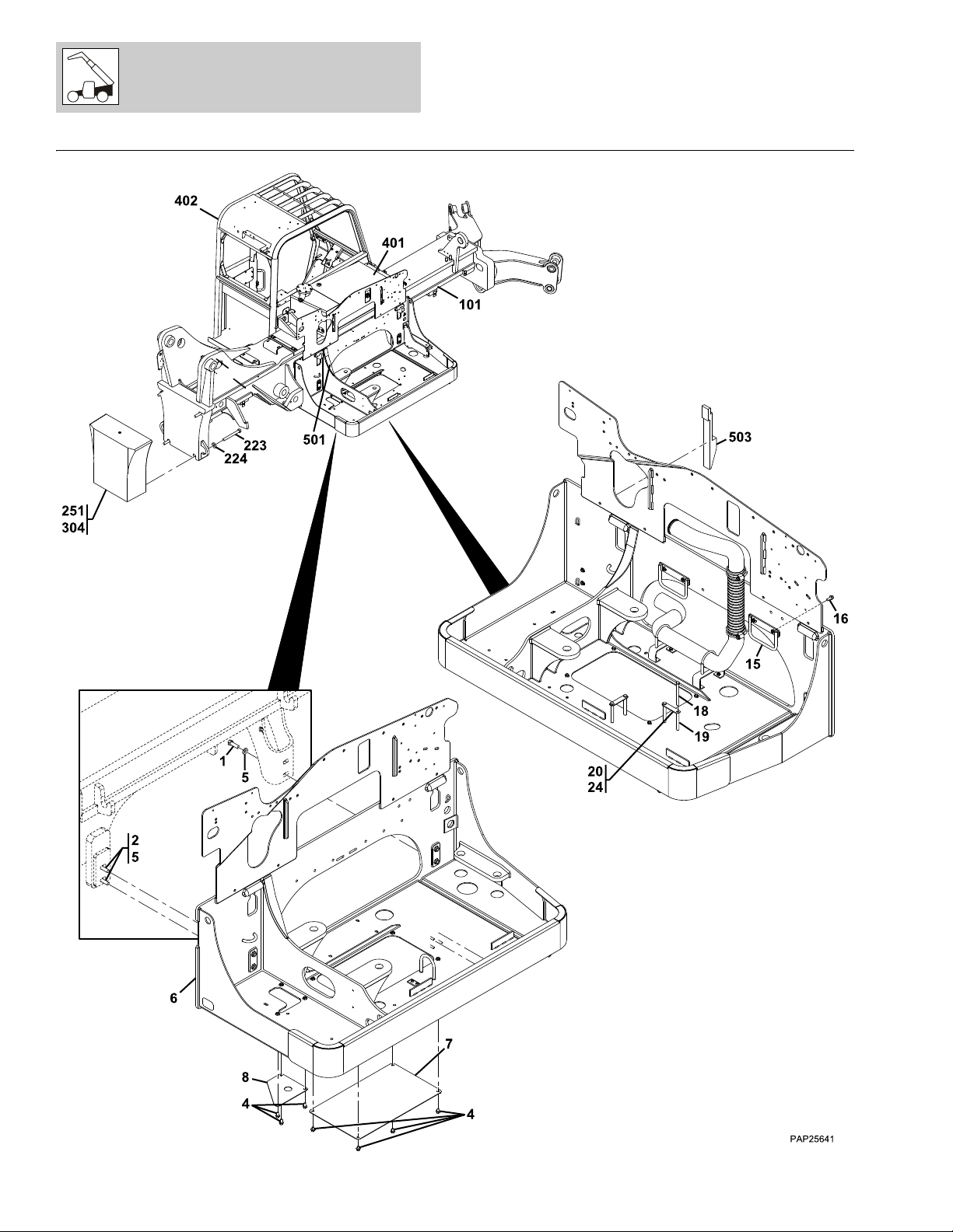
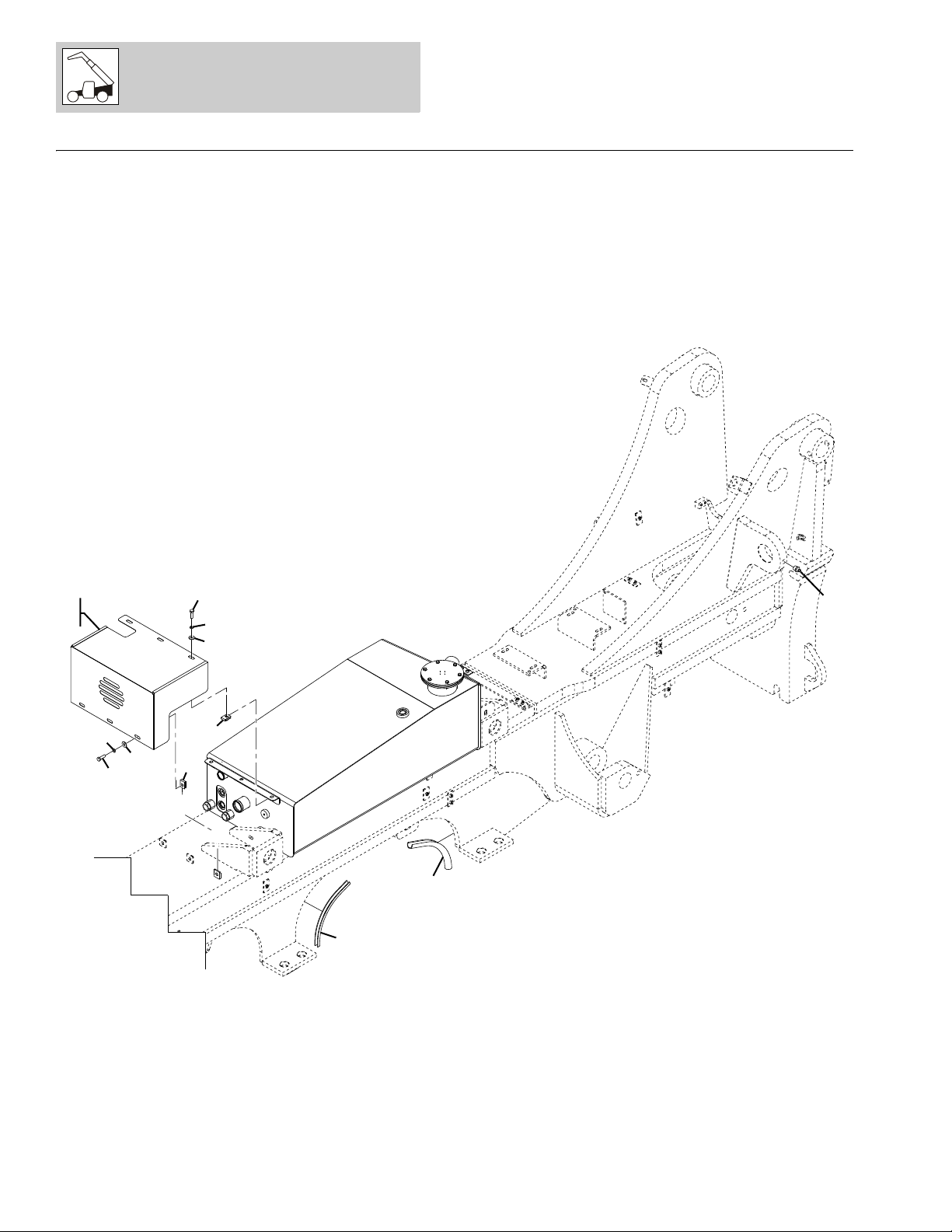
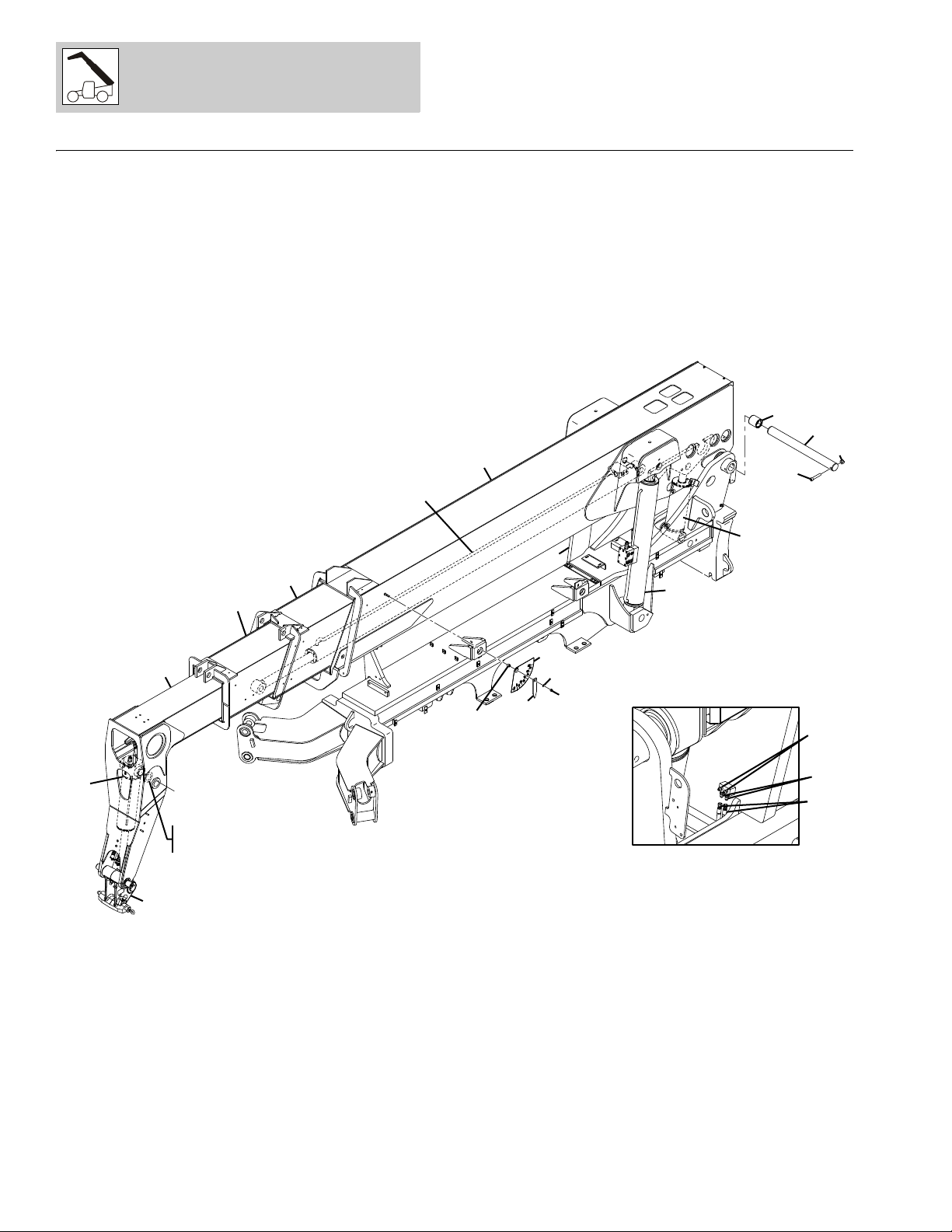
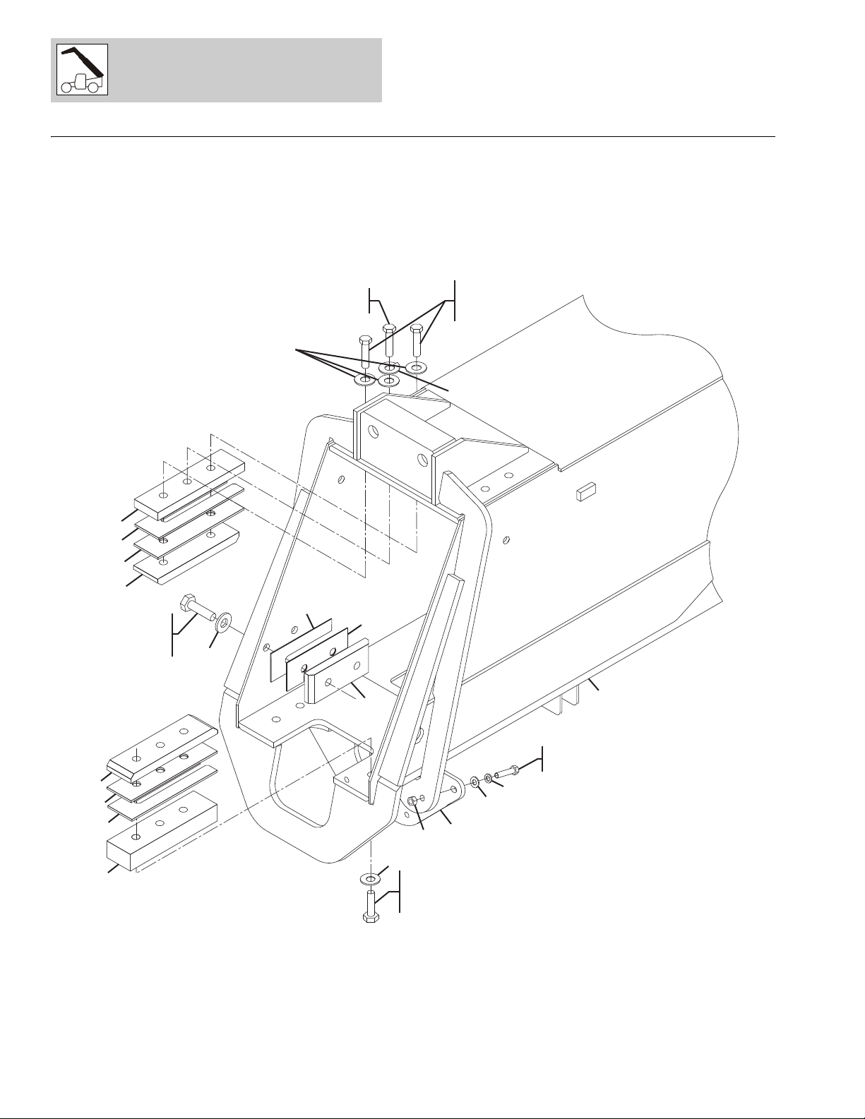
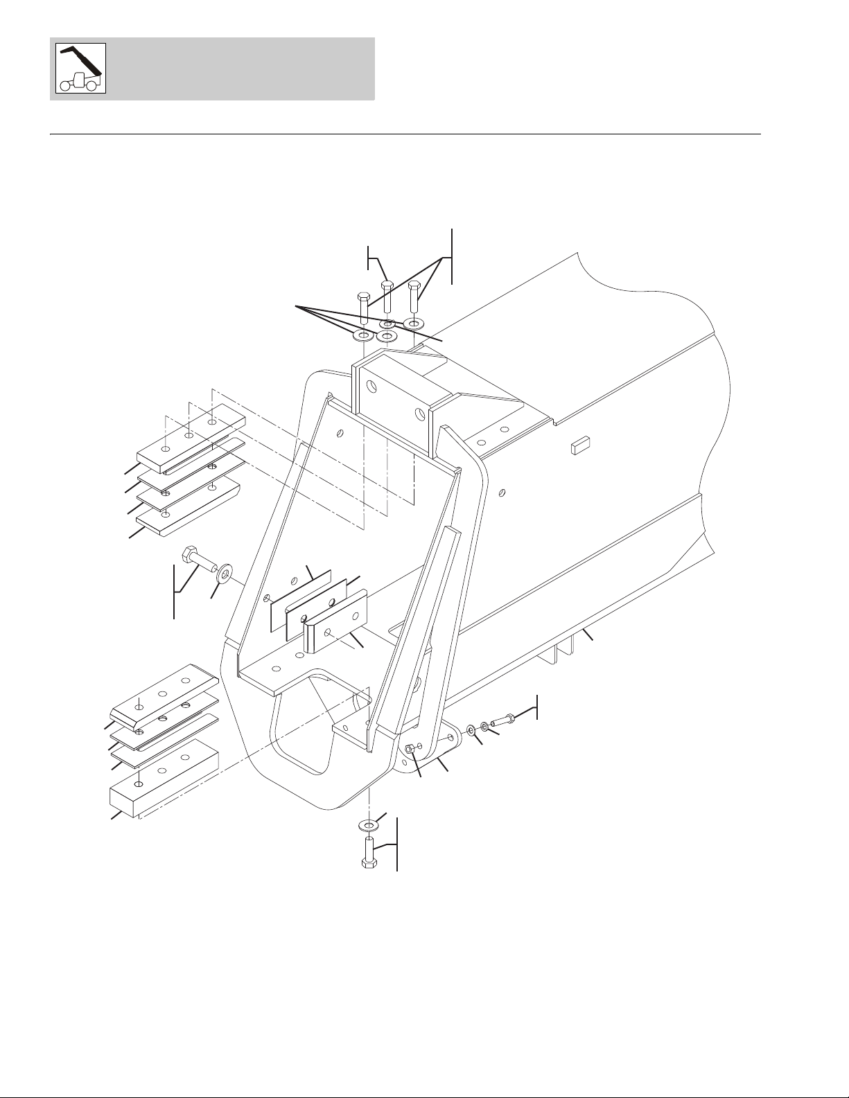
Figure 1-1 Frame & Attaching Parts
G10-55A, G12-55A 312007281-2

FRAME & ATTACHING PARTS
Figure 1-1 Frame & Attaching Parts
Item Part Number Qty. Description Rev.
1001130125 Ref ENGINE POD INSTALLATION, (if equipped for ULS), (not available to order,
see items 1 thru 24 for service)
1001136089 Ref ENGINE POD INSTALLATION, (if equipped for LS), (not available to order, see
items 1 thru 24 for service)
1 0682018 2 HEX HD CAPSCREW, 5/8-11X2-1/4
2 0682032 2 HEX HD CAPSCREW, 5/8-11X4
4 0811606 7 SCREW, 3/8-16X3/4
5 4892000 4 WASHER, 5/8
6 1001121031 1 POD WELDMENT SUPPORT
7 1001121047 1 BOTTOM COVER PLATE
8 1001128248 1 COOLER ACCESS COVER PLATE
15 1001132796 2 HOSE GUIDE BRACKET
16 0811610 4 SCREW, 3/8-16X1-1/4
18 0641640 4 HEX HD CAPSCREW, 3/8-16X5
19 1001143653 4 SPACER TUBE
20 1001123654 2 HOSE GUIDE PLATE
24 1001150299 2 HOSE, 3/4
101 NSS 1 FRAME WELDMENT
223 83201147 4 HEX HD CAPSCREW, 1-8X8-1/2, GR8, (torque to 860 lb-ft/1170 Nm)
224 80241137 4 WASHER
251 91140001 1 COUNTERWEIGHT, (if equipped)
1001097095 1 COUNTERWEIGHT WITH PINTLE HITCH ASSY, (if equipped),
(includes items 303 & 304)
303 Ref PINTLE HOOK, (not shown), (see Figure 1-4 for details)
304 1001091458 1 COUNTERWEIGHT
401 Ref HYDRAULIC TANK, (see Figure 9-14 for details)
402 Ref CAB WELDMENT, (see Figure 6-1 for details)
501 90206202 11 in TRIM-LOK
502 4060918 39 in TRIM-LOK, (not shown)
503 1001125491 1 FOAM GASKET SEAL
H
E
B
31200728 G10-55A, G12-55A 1-3
FRAME & ATTACHING PARTS
PAP25591
201
202
3
11
25
17
26
25
3
11
14
14
203
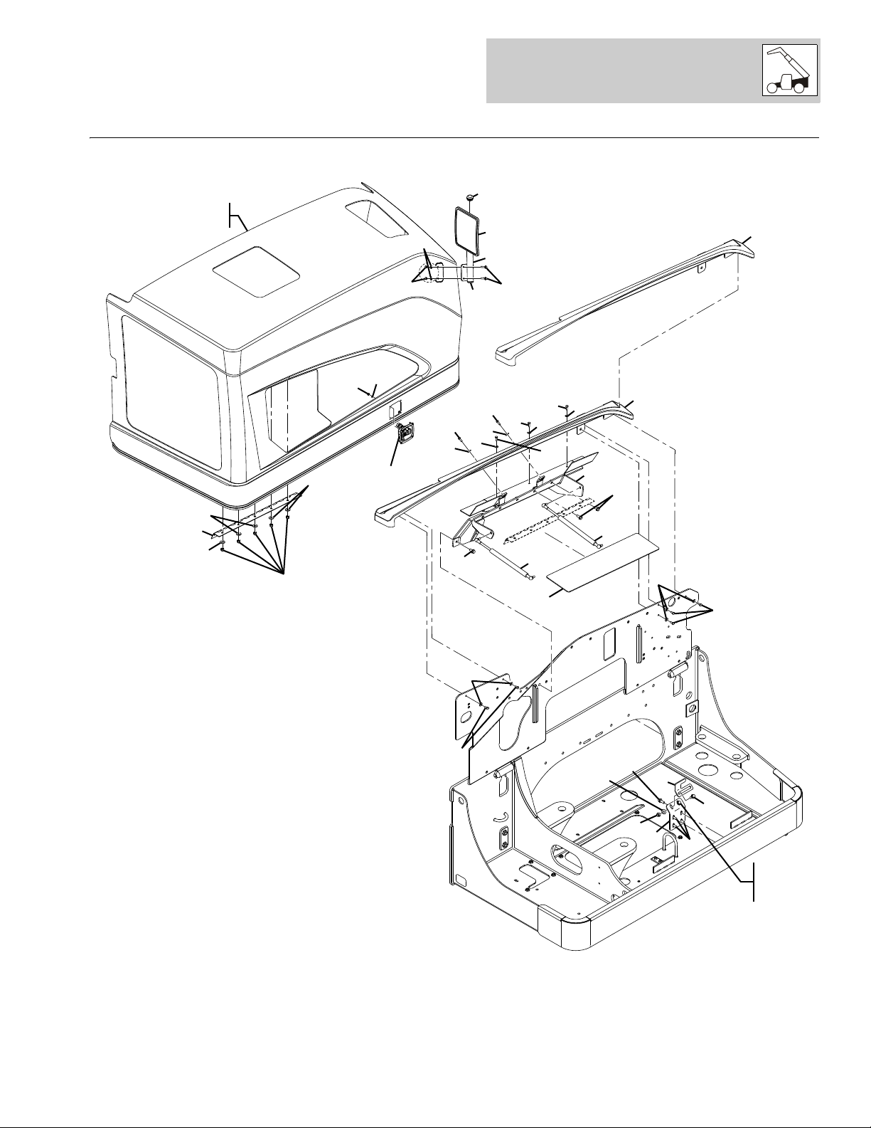
Figure 1-2 Covers
G10-55A, G12-55A 312007281-4
PAP25600
8
8
12
19
4
7
10
16
15
13
11
5
5
5
5
11
13
18
10
10
24
24
24
24
24
23
23
20
21
108
107
110
111
111
111
101
103
6
6
1
1
10
104
10
10
10
10
27
28
FRAME & ATTACHING PARTS
Figure 1-2 Covers (Continued)
31200728 G10-55A, G12-55A 1-5

FRAME & ATTACHING PARTS
Figure 1-2 Covers
Item Part Number Qty. Description Rev.
1001129636 Ref COVERS INSTALLATION, (not available to order, see items 1 thru 28
for service)
1 0641405 10 HEX HD CAPSCREW, 1/4-20X5/8, GR5
3 0641610 5 HEX HD CAPSCREW, 3/8-16X1-1/4, GR5
4 0791410 2 SCREW, 1/4-20X1-1/4
5 0791608 6 SCREW, 3/8-16X1
6 0811606 5 SCREW, 3/8-16X3/4
7 3311405 2 HEX LOCKNUT, 1/4-20
8 3520176 2 PLUG
10 4751400 12 WASHER, 1/4
11 4751600 7 WASHER, 3/8
12 8866348 1 RH MIRROR, (includes washer & locknut)
13 88501006 2 HEX NUT, 3/8-16
14 88662523 5 TINNERMAN NUT
15 1001121332 1 LATCH MOUNT BRACKET
16 1001121337 1 LATCH CATCH BRACKET
17 1001149900 1 FRONT COVER
18 1001129637 1 HINGE COVER
19 1001129639 1 MIRROR BRACKET
20 1001144114 1 HINGE MOUNT SUPPORT
21 1001131147 1 ENGINE ASSY COVER, (includes items 101 thru 111) F
23 1001131247 2 GAS SPRING
24 0811608 6 SCREW, 3/8-16X1
25 4761600 5 LOCKWASHER, 3/8
26 90206198 3 in TRIM-LOK
27 1001146367 1 INSULATE
28 1001146371 1 INSULATE
101 3290605 4 HEX LOCKNUT, M6X1
103 4811700 4 WASHER, 6mm
104 1001122219 1 COMPRESSION LATCH
107 1001129358 1 ENGINE COVER HINGE
108 1001129638 1 ENGINE COVER
110 3300492 5 LOCKING NUT
111 4751600 5 WASHER, 3/8
201 1001144101 15.5 in SPLIT CONDUIT
202 90206203 13.5 in TRIM-LOK
203 88671001 2 GREASE FITTING, 1/8
I
G10-55A, G12-55A 312007281-6

FRAME & ATTACHING PARTS
Figure 1-2 Covers (Continued)
Item Part Number Qty. Description Rev.
31200728 G10-55A, G12-55A 1-7
FRAME & ATTACHING PARTS
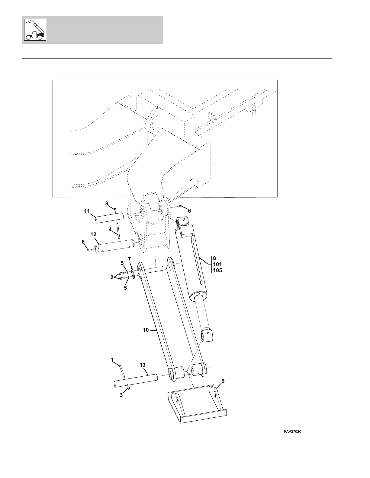
Figure 1-3 Outrigger Installation
G10-55A, G12-55A 312007281-8

FRAME & ATTACHING PARTS
Figure 1-3 Outrigger Installation
Item Part Number Qty. Description Rev.
1001143633 Ref OUTRIGGER INSTALLATION, (includes items 1 thru 13) A
1 0641634 2 HEX HD CAPSCREW, 3/8-16X4-1/4, GR5
2 0641808 4 HEX HD CAPSCREW, 1/2-13X1, GR5
3 3300143 4 HEX LOCKNUT, 3/8-16
4 3931672 2 SOCKET HD CAPSCREW, 3/8-16X4-1/2, GR8
5 4761800 4 LOCKWASHER, 1/2
6 88671001 4 LUBE FITTING, STRAIGHT, 1/8
7 91081313 2 KEEPER
8 1001001211 2 OUTRIGGER CYLINDER ASSY, (includes items 101 & 105) B
9 1001141892 2 PAD WELD STABILIZER
10 1001142258 2 OUTRIGGER ARM WELDMENT
11 91563197 2 OUTRIGGER CYLINDER PIN
12 91563198 2 ARM PIN
13 91563199 2 SHOE PIN
101 Ref OUTRIGGER CYLINDER & ATTACHING HARDWARE,
(see Figure 9-6 for details)
105 Ref STRAIGHT FITTING, (see Figure 8-14 for details)
31200728 G10-55A, G12-55A 1-9
FRAME & ATTACHING PARTS
301
303
304
305
PY7310
302
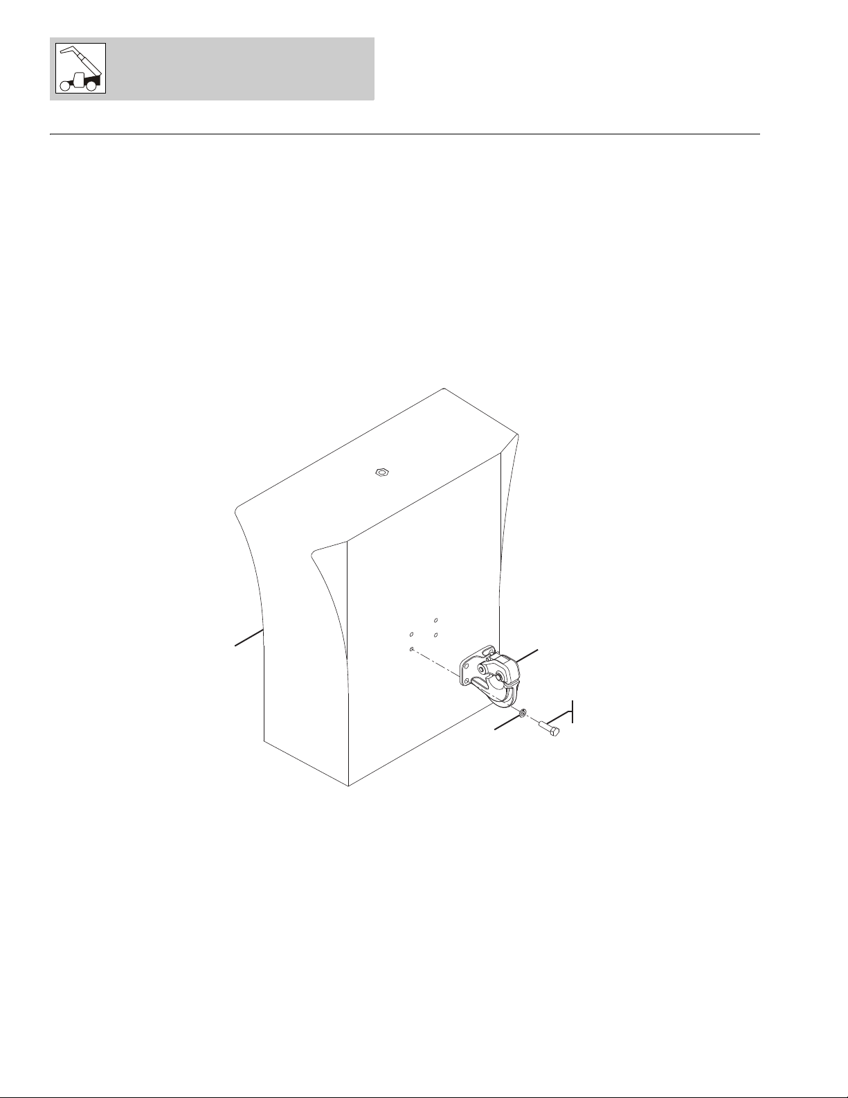
Figure 1-4 Pintle Hook
G10-55A, G12-55A 312007281-10

FRAME & ATTACHING PARTS
Figure 1-4 Pintle Hook
Item Part Number Qty. Description Rev.
®
301 0100011 AR
LOCTITE
302 0681814 4 HEX HD CAPSCREW, 1/2-13X1-3/4, GR8, (torque to 105 lb-ft/145 Nm)
303 88551013 4 LOCKWASHER, 1/2
304 90200602 1 PINTLE HOOK
305 Ref COUNTERWEIGHT, (see Figure 1-1 for details)
242
TM
31200728 G10-55A, G12-55A 1-11

FRAME & ATTACHING PARTS
This Page Intentionally Left Blank
G10-55A, G12-55A 312007281-12
SECTION 2
BOOM
31200728 G10-55A, G12-55A
BOOM
PAP25812
3
13
14
501
602
101
102
103
104
333
332
326
331
307
240
241
601
20
18
19
120
401
BACK OF FRAME
502
501
Figure 2-1 Boom Installation
G10-55A, G12-55A 312007282-2

BOOM
Figure 2-1 Boom Installation
Item Part Number Qty. Description Rev.
1001099663 Ref BOOM INSTALLATION, (G10-55A), (not available to order, see items 3 thru 20
for service)
1001099662 Ref BOOM INSTALLATION, (G12-55A), (not available to order, see items 3 thru 20
for service)
3 3423247 1 PIN
13 88212287 1 SOCKET HD CAPSCREW, 3/4-10X6
14 8310067 1 HEX LOCKNUT, 3/4-10
18 88661002 2 STRAIGHT FITTING
19 84719940 2 HOSE ASSY
20 2160002 2 GREASE FITTING
1001113744B 1 BOOM ASSY, (G10-55A), (includes items 101 thru 106 & 120 thru 241) D
1001114138B 1 BOOM ASSY, (G12-55A), (includes items 101 thru 106 & 120 thru 241) D
101 Ref FIRST BOOM SECTION, (see Figure 2-2 for details)
102 Ref SECOND BOOM SECTION, (see Figure 2-3 for details)
103 Ref THIRD BOOM SECTION, (see Figure 2-4 for details)
104 Ref FOURTH BOOM SECTION, (see Figure 2-5 for details)
105 Ref EXTEND CHAINS, (not shown), (see Figure 2-6 for details)
106 Ref RETRACT CHAINS, (not shown), (see Figure 2-7 for details)
120 91141301 2 BUSHING
125 Ref BOOM HYDRAULICS, (not shown), (see Figure 8-11 for details)
240 8307916 AR SHIM, 2.5X3.875X.075
241 8307917 AR SHIM, 2.5X3.875X.134
307 Ref ANGLE DECAL, (see Figure 11-2 for details)
326 1001098769 1 BOOM ANGLE INDICATOR
331 1001096404 1 BOOM ANGLE SPACER
332 4711600 1 WASHER, 3/8
333 8305645 1 HEX LOCKNUT, 3/8-16
401 Ref MECHANICAL QUICK ATTACH INSTALLATION, (see Figure 2-8 for details)
501 Ref LIFT CYLINDER & HARDWARE, (see Figure 9-1 for details)
502 Ref COMPENSATION CYLINDER & HARDWARE, (see Figure 9-4 for details)
601 Ref TILT CYLINDER & HARDWARE, (see Figure 9-3 for details)
602 Ref EXTEND/RETRACT CYLINDER & HARDWARE, (see Figure 9-2 for details)
I
I
31200728 G10-55A, G12-55A 2-3
BOOM
PY8310
121
129
201
75
41
54
53
44
74
76
201
95
55
52
45
51
60
63
46
95
81
131
201
107
113
201
1
13
62
201
133
81
86
G10-55A
Note: Wear Pad Shimming:
Whenever a shim is used with a pad, a spacer with holes must be inserted between pad & shim.
The wear pad or wear pad insert must not sit directly on the slotted surface of shims.
Add wear pad shims & spacers as required to shim boom to maintain a total minimum gap of 0.070 to 0.130 in (1,8 to 3,3 mm) in
both horizontal & vertical directions.
Wear pad bolts require one hardened washer. However, up to (2) hardened washers may be used except where noted otherwise.
Under no circumstances should more than (2) hardened washers ever be used.
The length of pad bolts depends on the number of the shims used. The bolt cannot extend past chamfer on wear pad.
Add Mystik Tetrimoly Grease (14404793) to all wear pads & all wear pad slide pathways. If applicable, this includes all pad grease
fittings at the rear of boom.
Figure 2-2 First Boom Section
G10-55A, G12-55A 312007282-4

BOOM
Figure 2-2 First Boom Section
Item Part Number Qty. Description Rev.
1 1001113588 1 FIRST BOOM SECTION WELDMENT
13 91561156B 1 EXTEND/RETRACT CYLINDER SUPPORT PLATE
38 91161171 2 WEAR PAD SUPPORT
41 91161167 2 WEAR PAD SUPPORT
43 91033189 2 WEAR PAD
44 1001117653 2 WEAR PAD
45 91033186 4 WEAR PAD
52 91031236 6 SPACER
53 91161183 2 SPACER
54 91161184 AR SHIM, 0.0598
55 90205870 AR SHIM, 0.0598
62 0641818 2 HEX HD CAPSCREW, 1/2-13X2-1/4, GR5, (torque to 85 lb-ft/116 Nm)
74 0651607 AR HEX HD CAPSCREW, 3/8-24X.88, GR5, (torque to 32-37 lb-ft/43-50 Nm)
76 0651606 AR HEX HD CAPSCREW, 3/8-24X3/4, GR5, (torque to 32-37 lb-ft/43-50 Nm)
81 4761800 4 SPRING LOCKWASHER
86 3311801 2 HEX NUT, 1/2-13
95 4891600 14 WASHER, 3/8
107 0651612 AR HEX HD CAPSCREW, 3/8-24X1-1/2, GR5, (torque to 32-37 lb-ft/43-50 Nm)
113 0651614 AR HEX HD CAPSCREW, 3/8-24X1-3/4, GR5, (torque to 32-37 lb-ft/43-50 Nm)
121 0651820 AR HEX HD CAPSCREW, 1/2-20X2-1/2, GR5, (torque to 76-86 lb-ft/103-117 Nm)
129 0651822 AR HEX HD CAPSCREW, 1/2-20X2-3/4, GR5, (torque to 76-86 lb-ft/103-117 Nm)
131 0641810 2 HEX HD CAPSCREW, 1/2-13X1-1/4, GR5, (torque to 76-86 lb-ft/103-117 Nm)
133 4711800 2 WASHER, 1/2
®
201 0100011 AR
LOCTITE
242
™
31200728 G10-55A, G12-55A 2-5
BOOM
PY7080
75
101
128
201
74
41
54
53
44
92
130
131
201
91
55
52
45
43
52
55
38
91
79
106
201
61
76
77
201
1
13
62
201
143
79
83
G12-55A
Note: Wear Pad Shimming:
Whenever a shim is used with a pad, a spacer with holes must be inserted between pad & shim.
The wear pad or wear pad insert must not sit directly on the slotted surface of shims.
Add wear pad shims & spacers as required to shim boom to maintain a total minimum gap of 0.070 to 0.130 in (1,8 to 3,3 mm) in
both horizontal & vertical directions.
Wear pad bolts require one hardened washer. However, up to (2) hardened washers may be used except where noted otherwise.
Under no circumstances should more than (2) hardened washers ever be used.
The length of pad bolts depends on the number of the shims used. The bolt cannot extend past chamfer on wear pad.
Add Mystik Tetrimoly Grease (14404793) to all wear pads & all wear pad slide pathways. If applicable, this includes all pad grease
fittings at the rear of boom.
Figure 2-2 First Boom Section
G10-55A, G12-55A 312007282-6
Loading...