


Model
M45A
M45AJ
E45A
E45AJ
B S E N I S O 90 01 C er tificat e N o. 6 917
CORPORATE OFFICE |
EUROPEAN OFFICE |
AUSTRALIAN OFFICE |
||
JLG INDUSTRIES, INC. |
JLG INDUSTRIES (EUROPE) |
JLG INDUSTRIES (AUSTRALIA) |
||
1 JLG Drive |
Kilmartin Place, |
P.0. Box 972 |
||
McConnellsburg, PA 17233-9533 |
Tannochside Park, |
11 Bolwarra Road |
||
USA |
Uddingston, Scotland, G71 5PH |
Port MacQuarie |
||
Telephone: (717) 485-5161 |
Telephone: 01698 811005 |
N.S.W. 44 |
||
Fax: (717) 485-6417 |
Fax: 01698 811055 |
Australia |
||
|
|
|
|
Telephone: 1 (065) 811111 |
|
|
|
|
|
|
|
|
|
|
Issued: August 5, 1999 |
PRINTED IN U.S.A. |
3120884 |
||
SERVICE & MAINTENANCE
Updated: February 15, 2000

INTRODUCTION
SECTION A. INTRODUCTION - MAINTENANCE SAFETY
PRECAUTIONS
A GENERAL
This section contains the general safety precautions which must be observed during maintenance of the aerial platform. It is of utmost importance that maintenance personnel pay strict attention to these warnings and precautions to avoid possible injury to themselves or others, or damage to the equipment. A maintenance program must be followed to ensure that the machine is safe to operate.
MODIFICATION OF THE MACHINE WITHOUT CERTIFICATION BY
A RESPONSIBLE AUTHORITY THAT THE MACHINE IS AT LEAST AS SAFE AS ORIGINALLY MANUFACTURED, IS A SAFETY VIOLA-
TION.
The specific precautions to be observed during maintenance are inserted at the appropriate point in the manual. These precautions are, for the most part, those that apply when servicing hydraulic and larger machine component parts.
Your safety, and that of others, is the first consideration when engaging in the maintenance of equipment. Always be conscious of weight. Never attempt to move heavy parts without the aid of a mechanical device. Do not allow heavy objects to rest in an unstable position. When raising a portion of the equipment, ensure that adequate support is provided.
SINCE THE MACHINE MANUFACTURER HAS NO DIRECT CONTROL OVER THE FIELD INSPECTION AND MAINTENANCE,
SAFETY IN THIS AREA RESPONSIBILITY OF THE OWNER/OPER-
ATOR.
C MAINTENANCE
FAILURE TO COMPLY WITH SAFETY PRECAUTIONS LISTED IN
THIS SECTION MAY RESULT IN MACHINE DAMAGE, PERSONNEL
INJURY OR DEATH AND IS A SAFETY VIOLATION.
•NO SMOKING IS MANDATORY. NEVER REFUEL DURING ELECTRICAL STORMS. ENSURE THAT FUEL CAP IS CLOSED AND SECURE AT ALL OTHER TIMES.
•REMOVE ALL RINGS, WATCHES AND JEWELRY WHEN PERFORMING ANY MAINTENANCE.
•DO NOT WEAR LONG HAIR UNRESTRAINED, OR LOOSE-FITTING CLOTHING AND NECKTIES WHICH ARE APT TO BECOME CAUGHT ON OR ENTANGLED IN EQUIPMENT.
•OBSERVE AND OBEY ALL WARNINGS AND CAUTIONS ON MACHINE AND IN SERVICEMANUAL.
•KEEP OIL, GREASE, WATER, ETC. WIPED FROM STANDING SURFACES AND HAND HOLDS.
•USE CAUTION WHEN CHECKING A HOT, PRESSURIZED COOLANT SYSTEM.
•NEVER WORK UNDER AN ELEVATED BOOM UNTIL BOOM HAS BEEN SAFELY RESTRAINED FROM ANY MOVEMENT BY BLOCKING OR OVERHEAD SLING, OR BOOM SAFETY PROP HAS BEEN ENGAGED.
•BEFORE MAKING ADJUSTMENTS, LUBRICATING OR PERFORMING ANY OTHER MAINTENANCE, SHUT OFF ALL POWER CONTROLS.
•BATTERY SHOULD ALWAYS BE DISCONNECTEDDURING REPLACEMENT OF ELECTRICAL COMPONENTS.
B HYDRAULIC SYSTEM SAFETY
It should be noted that the machines hydraulic systems operate at extremely high potentially dangerous pressures. Every effort should be made to relieve any system pressure prior to disconnecting or removing any portion of the system.
Relieve system pressure by cycling the applicable control several times with the engine stopped and ignition on, to direct any line pressure back into the reservoir. Pressure feed lines to system components can then be disconnected with minimal fluid loss.
•KEEP ALL SUPPORT EQUIPMENT AND ATTACHMENTS STOWED IN THEIR PROPER PLACE.
•USE ONLY APPROVED, NONFLAMMABLE CLEANING SOLVENTS.
3120884 |
– JLG Lift – |
A-1 |

INTRODUCTION
|
REVISON LOG |
August 5, 1999 |
- Original Issue |
2-40 |
- Updated 8-30-99 |
1-1 and 1-2 |
- Updated 10-7-99 |
2-50 |
- Updated 10-7-99 |
2-52 thru 2-54 |
- Updated 10-7-99 |
1-1 |
- Updated 2-15-00 |
3-1 |
- Updated 2-15-00 |
3-5 |
- Updated 2-15-00 |
3-16 |
- Updated 2-15-00 |
A-2 |
– JLG Lift – |
3120884 |

TABLE OF CONTENTS
TABLE OF CONTENTS |
|
SUBJECT - SECTION, PARAGRAPH |
PAGE NO. |
SECTION A - INTRODUCTION - MAINTENANCE SAFETY PRECAUTIONS |
|
A General . . . . . . . . . . . . . . . . . . . . . . . . . . . . . . . . . . . . . . . . . . . . . . . . . . . . . . . . . . . . . . . . . . . . . .A-1
B Hydraulic System Safety . . . . . . . . . . . . . . . . . . . . . . . . . . . . . . . . . . . . . . . . . . . . . . . . . . . . . . . . .A-1
C Maintenance . . . . . . . . . . . . . . . . . . . . . . . . . . . . . . . . . . . . . . . . . . . . . . . . . . . . . . . . . . . . . . . . . .A-1
SECTION 1 - SPECIFICATIONS
1.1 Capacities . . . . . . . . . . . . . . . . . . . . . . . . . . . . . . . . . . . . . . . . . . . . . . . . . . . . . . . . . . . . . . . . . . . .1-1
1.2 Component Data . . . . . . . . . . . . . . . . . . . . . . . . . . . . . . . . . . . . . . . . . . . . . . . . . . . . . . . . . . . . . . .1-1
1.3 Performance Data . . . . . . . . . . . . . . . . . . . . . . . . . . . . . . . . . . . . . . . . . . . . . . . . . . . . . . . . . . . . . .1-1
1.4 Function Speeds (M45A/E45A). . . . . . . . . . . . . . . . . . . . . . . . . . . . . . . . . . . . . . . . . . . . . . . . . . . .1-2
1.5 Function Speeds (M45AJ/E45AJ) . . . . . . . . . . . . . . . . . . . . . . . . . . . . . . . . . . . . . . . . . . . . . . . . . .1-2
1.6 Torque Specifications . . . . . . . . . . . . . . . . . . . . . . . . . . . . . . . . . . . . . . . . . . . . . . . . . . . . . . . . . . .1-3
1.7 Lubrication. . . . . . . . . . . . . . . . . . . . . . . . . . . . . . . . . . . . . . . . . . . . . . . . . . . . . . . . . . . . . . . . . . . .1-3
1.8 Pressure Settings . . . . . . . . . . . . . . . . . . . . . . . . . . . . . . . . . . . . . . . . . . . . . . . . . . . . . . . . . . . . . .1-4
1.9 Cylinder Specifications . . . . . . . . . . . . . . . . . . . . . . . . . . . . . . . . . . . . . . . . . . . . . . . . . . . . . . . . . .1-4
1.10 Major Component Weights . . . . . . . . . . . . . . . . . . . . . . . . . . . . . . . . . . . . . . . . . . . . . . . . . . . . . . .1-4
1.11 Critical Stability Weights . . . . . . . . . . . . . . . . . . . . . . . . . . . . . . . . . . . . . . . . . . . . . . . . . . . . . . . . .1-4
1.12 Serial Number Locations. . . . . . . . . . . . . . . . . . . . . . . . . . . . . . . . . . . . . . . . . . . . . . . . . . . . . . . . .1-5
SECTION 2 - PROCEDURES
2.1 General . . . . . . . . . . . . . . . . . . . . . . . . . . . . . . . . . . . . . . . . . . . . . . . . . . . . . . . . . . . . . . . . . . . . . .2-1 2.2 Servicing and Maintenance Guidelines . . . . . . . . . . . . . . . . . . . . . . . . . . . . . . . . . . . . . . . . . . . . .2-1 2.3 Lubrication Information . . . . . . . . . . . . . . . . . . . . . . . . . . . . . . . . . . . . . . . . . . . . . . . . . . . . . . . . . .2-3 2.4 Battery Maintenance and Charging . . . . . . . . . . . . . . . . . . . . . . . . . . . . . . . . . . . . . . . . . . . . . . . .2-4 2.5 Cylinders - Theory of Operation . . . . . . . . . . . . . . . . . . . . . . . . . . . . . . . . . . . . . . . . . . . . . . . . . . .2-6 2.6 Cylinder Checking Procedures . . . . . . . . . . . . . . . . . . . . . . . . . . . . . . . . . . . . . . . . . . . . . . . . . . . .2-7 2.7 Cylinder Repair . . . . . . . . . . . . . . . . . . . . . . . . . . . . . . . . . . . . . . . . . . . . . . . . . . . . . . . . . . . . . . . .2-8 2.8 Cylinder Removal and Installation . . . . . . . . . . . . . . . . . . . . . . . . . . . . . . . . . . . . . . . . . . . . . . . . .2-14 2.9 Wear Pads . . . . . . . . . . . . . . . . . . . . . . . . . . . . . . . . . . . . . . . . . . . . . . . . . . . . . . . . . . . . . . . . . . . .2-17 2.10 Boom Maintenance . . . . . . . . . . . . . . . . . . . . . . . . . . . . . . . . . . . . . . . . . . . . . . . . . . . . . . . . . . . . .2-17 2.11 Rotator - Helac. . . . . . . . . . . . . . . . . . . . . . . . . . . . . . . . . . . . . . . . . . . . . . . . . . . . . . . . . . . . . . . . .2-21 2.12 Boom Limit Switches. . . . . . . . . . . . . . . . . . . . . . . . . . . . . . . . . . . . . . . . . . . . . . . . . . . . . . . . . . . .2-24 2.13 Articulating Jib Boom . . . . . . . . . . . . . . . . . . . . . . . . . . . . . . . . . . . . . . . . . . . . . . . . . . . . . . . . . . .2-26 2.14 Swing Bearing . . . . . . . . . . . . . . . . . . . . . . . . . . . . . . . . . . . . . . . . . . . . . . . . . . . . . . . . . . . . . . . . .2-27 2.15 Mid and Lower Lift Cylinder Bleeding Procedure . . . . . . . . . . . . . . . . . . . . . . . . . . . . . . . . . . . . . .2-32 2.16 Boom Synchronizing Procedure . . . . . . . . . . . . . . . . . . . . . . . . . . . . . . . . . . . . . . . . . . . . . . . . . . .2-32 2.17 Drive Hub. . . . . . . . . . . . . . . . . . . . . . . . . . . . . . . . . . . . . . . . . . . . . . . . . . . . . . . . . . . . . . . . . . . . .2-32 2.18 Drive Brake - Mico . . . . . . . . . . . . . . . . . . . . . . . . . . . . . . . . . . . . . . . . . . . . . . . . . . . . . . . . . . . . . .2-34 2.19 Pins and Gar-max Bearing Repair Guidelines . . . . . . . . . . . . . . . . . . . . . . . . . . . . . . . . . . . . . . . .2-36 2.20 Speed Sensor Adjustment . . . . . . . . . . . . . . . . . . . . . . . . . . . . . . . . . . . . . . . . . . . . . . . . . . . . . . .2-36 2.21 Footswitch Adjustment . . . . . . . . . . . . . . . . . . . . . . . . . . . . . . . . . . . . . . . . . . . . . . . . . . . . . . . . . .2-40 2.22 Positrac/Tilt module. . . . . . . . . . . . . . . . . . . . . . . . . . . . . . . . . . . . . . . . . . . . . . . . . . . . . . . . . . . . .2-40 2.23 Pressure Setting Procedures . . . . . . . . . . . . . . . . . . . . . . . . . . . . . . . . . . . . . . . . . . . . . . . . . . . . .2-41 2.24 JLG Control System Analyzer Kit Instructions . . . . . . . . . . . . . . . . . . . . . . . . . . . . . . . . . . . . . . . .2-45 2.25 Generator. . . . . . . . . . . . . . . . . . . . . . . . . . . . . . . . . . . . . . . . . . . . . . . . . . . . . . . . . . . . . . . . . . . . .2-70 2.26 Preventive Maintenance and Inspection Schedule. . . . . . . . . . . . . . . . . . . . . . . . . . . . . . . . . . . . .2-76
SECTION 3 - TROUBLESHOOTING
3.1 General . . . . . . . . . . . . . . . . . . . . . . . . . . . . . . . . . . . . . . . . . . . . . . . . . . . . . . . . . . . . . . . . . . . . . .3-1
3.2 Troubleshooting. . . . . . . . . . . . . . . . . . . . . . . . . . . . . . . . . . . . . . . . . . . . . . . . . . . . . . . . . . . . . . . .3-1
3.3 Hydraulic Circuit Checks. . . . . . . . . . . . . . . . . . . . . . . . . . . . . . . . . . . . . . . . . . . . . . . . . . . . . . . . .3-1
3120884 |
– JLG Lift – |
i |

TABLE OF CONTENTS
LIST OF FIGURES
FIGURE NO. TITLE |
PAGE NO. |
1-1. Serial Number Locations. . . . . . . . . . . . . . . . . . . . . . . . . . . . . . . . . . . . . . . . . . . . . . . . . . . . . . . . .1-5 1-2. Torque Chart . . . . . . . . . . . . . . . . . . . . . . . . . . . . . . . . . . . . . . . . . . . . . . . . . . . . . . . . . . . . . . . . . .1-6 1-3. Lubrication Diagram . . . . . . . . . . . . . . . . . . . . . . . . . . . . . . . . . . . . . . . . . . . . . . . . . . . . . . . . . . . .1-7 2-1. On Board Generator . . . . . . . . . . . . . . . . . . . . . . . . . . . . . . . . . . . . . . . . . . . . . . . . . . . . . . . . . . . .2-5 2-2. Batteries and Battery Charger. . . . . . . . . . . . . . . . . . . . . . . . . . . . . . . . . . . . . . . . . . . . . . . . . . . . .2-6 2-3. Cylinder Barrel Support. . . . . . . . . . . . . . . . . . . . . . . . . . . . . . . . . . . . . . . . . . . . . . . . . . . . . . . . . .2-8 2-4. Capscrew Removal . . . . . . . . . . . . . . . . . . . . . . . . . . . . . . . . . . . . . . . . . . . . . . . . . . . . . . . . . . . . .2-8 2-5. Cylinder Rod Support . . . . . . . . . . . . . . . . . . . . . . . . . . . . . . . . . . . . . . . . . . . . . . . . . . . . . . . . . . .2-9 2-6. Tapered Bushing Removal . . . . . . . . . . . . . . . . . . . . . . . . . . . . . . . . . . . . . . . . . . . . . . . . . . . . . . .2-9 2-7. Gar-Max Bearing Installation . . . . . . . . . . . . . . . . . . . . . . . . . . . . . . . . . . . . . . . . . . . . . . . . . . . . . .2-10 2-8. Rod Seal Installation . . . . . . . . . . . . . . . . . . . . . . . . . . . . . . . . . . . . . . . . . . . . . . . . . . . . . . . . . . . .2-10 2-9. Wiper Seal Installation. . . . . . . . . . . . . . . . . . . . . . . . . . . . . . . . . . . . . . . . . . . . . . . . . . . . . . . . . . .2-10 2-10. Installation of Head Seal Kit . . . . . . . . . . . . . . . . . . . . . . . . . . . . . . . . . . . . . . . . . . . . . . . . . . . . . .2-11 2-11. Piston Seal Kit Installation . . . . . . . . . . . . . . . . . . . . . . . . . . . . . . . . . . . . . . . . . . . . . . . . . . . . . . . .2-11 2-12. Tapered Bushing Installation . . . . . . . . . . . . . . . . . . . . . . . . . . . . . . . . . . . . . . . . . . . . . . . . . . . . .2-12 2-13. Seating the Tapered Bearing . . . . . . . . . . . . . . . . . . . . . . . . . . . . . . . . . . . . . . . . . . . . . . . . . . . . .2-12 2-14. Poly-Pak Piston Seal Installation. . . . . . . . . . . . . . . . . . . . . . . . . . . . . . . . . . . . . . . . . . . . . . . . . . .2-12 2-15. Rod Assembly Installation. . . . . . . . . . . . . . . . . . . . . . . . . . . . . . . . . . . . . . . . . . . . . . . . . . . . . . . .2-13 2-16. Upper Boom Lift Cylinder Removal . . . . . . . . . . . . . . . . . . . . . . . . . . . . . . . . . . . . . . . . . . . . . . . .2-14 2-17. Mid Boom Lift Cylinder Removal. . . . . . . . . . . . . . . . . . . . . . . . . . . . . . . . . . . . . . . . . . . . . . . . . . .2-14 2-18. Lower Boom Lift Cylinder Removal. . . . . . . . . . . . . . . . . . . . . . . . . . . . . . . . . . . . . . . . . . . . . . . . .2-15 2-19. Upper Telescope Cylinder Removal . . . . . . . . . . . . . . . . . . . . . . . . . . . . . . . . . . . . . . . . . . . . . . . .2-16 2-20. Wear Pad Thickness . . . . . . . . . . . . . . . . . . . . . . . . . . . . . . . . . . . . . . . . . . . . . . . . . . . . . . . . . . . .2-17 2-21. Platform Components and Attaching Hardware (M45A & E45A). . . . . . . . . . . . . . . . . . . . . . . . . .2-18 2-22. Location of Components - Boom Removal. . . . . . . . . . . . . . . . . . . . . . . . . . . . . . . . . . . . . . . . . . . 2-19 2-23. Rotator Assembly (Helac) . . . . . . . . . . . . . . . . . . . . . . . . . . . . . . . . . . . . . . . . . . . . . . . . . . . . . . . .2-22 2-24. Removing End Cap . . . . . . . . . . . . . . . . . . . . . . . . . . . . . . . . . . . . . . . . . . . . . . . . . . . . . . . . . . . . .2-23 2-25. Removing Shaft from Housing . . . . . . . . . . . . . . . . . . . . . . . . . . . . . . . . . . . . . . . . . . . . . . . . . . . .2-23 2-26. Removing Sleeve from Housing . . . . . . . . . . . . . . . . . . . . . . . . . . . . . . . . . . . . . . . . . . . . . . . . . . .2-23 2-27. Actuator Timing . . . . . . . . . . . . . . . . . . . . . . . . . . . . . . . . . . . . . . . . . . . . . . . . . . . . . . . . . . . . . . . .2-24 2-28. Boom Limit Switches. . . . . . . . . . . . . . . . . . . . . . . . . . . . . . . . . . . . . . . . . . . . . . . . . . . . . . . . . . . .2-25 2-29. Location of Components - Articulating Jib Boom. . . . . . . . . . . . . . . . . . . . . . . . . . . . . . . . . . . . . .2-26 2-30. Swing Bearing Feeler Gauge Check. . . . . . . . . . . . . . . . . . . . . . . . . . . . . . . . . . . . . . . . . . . . . . . .2-27 2-32. Swing Bearing Tolerance Measuring Point . . . . . . . . . . . . . . . . . . . . . . . . . . . . . . . . . . . . . . . . . .2-27 2-31. Swing Bearing Tolerance Boom Placement . . . . . . . . . . . . . . . . . . . . . . . . . . . . . . . . . . . . . . . . . .2-28 2-33. Swing Bearing Torquing Sequence . . . . . . . . . . . . . . . . . . . . . . . . . . . . . . . . . . . . . . . . . . . . . . . .2-30 2-34. Swing Components. . . . . . . . . . . . . . . . . . . . . . . . . . . . . . . . . . . . . . . . . . . . . . . . . . . . . . . . . . . . .2-31 2-35. Drive Hub - Cutaway . . . . . . . . . . . . . . . . . . . . . . . . . . . . . . . . . . . . . . . . . . . . . . . . . . . . . . . . . . . .2-33 2-36. Drive Brake - Mico . . . . . . . . . . . . . . . . . . . . . . . . . . . . . . . . . . . . . . . . . . . . . . . . . . . . . . . . . . . . . .2-35 2-37. Speed Sensor Orientation. . . . . . . . . . . . . . . . . . . . . . . . . . . . . . . . . . . . . . . . . . . . . . . . . . . . . . . .2-37 2-38. Frame Mounted Electrical Components . . . . . . . . . . . . . . . . . . . . . . . . . . . . . . . . . . . . . . . . . . . . .2-38 2-39. Steering Components and Spindles. . . . . . . . . . . . . . . . . . . . . . . . . . . . . . . . . . . . . . . . . . . . . . . .2-39 2-40. Drive Components . . . . . . . . . . . . . . . . . . . . . . . . . . . . . . . . . . . . . . . . . . . . . . . . . . . . . . . . . . . . .2-40 2-41. Tilt Sensor Location. . . . . . . . . . . . . . . . . . . . . . . . . . . . . . . . . . . . . . . . . . . . . . . . . . . . . . . . . . . . .2-41 2-42. Jib Valve Location . . . . . . . . . . . . . . . . . . . . . . . . . . . . . . . . . . . . . . . . . . . . . . . . . . . . . . . . . . . . . .2-42 2-43. Brake/Steer Valve Components . . . . . . . . . . . . . . . . . . . . . . . . . . . . . . . . . . . . . . . . . . . . . . . . . . .2-43 2-44. Main Valve Components . . . . . . . . . . . . . . . . . . . . . . . . . . . . . . . . . . . . . . . . . . . . . . . . . . . . . . . . .2-44 2-45. Control Module Location. . . . . . . . . . . . . . . . . . . . . . . . . . . . . . . . . . . . . . . . . . . . . . . . . . . . . . . . .2-45 2-46. Analyzer Flow Chart - Sheet 1 of 2 . . . . . . . . . . . . . . . . . . . . . . . . . . . . . . . . . . . . . . . . . . . . . . . . .2-61 2-47. Analyzer Flow Chart - Sheet 2 of 2 . . . . . . . . . . . . . . . . . . . . . . . . . . . . . . . . . . . . . . . . . . . . . . . . .2-62 2-48. Generator Components . . . . . . . . . . . . . . . . . . . . . . . . . . . . . . . . . . . . . . . . . . . . . . . . . . . . . . . . .2-71 2-49. Generator System Analyzer Flow Chart . . . . . . . . . . . . . . . . . . . . . . . . . . . . . . . . . . . . . . . . . . . . .2-74
ii |
– JLG Lift – |
3120884 |

TABLE OF CONTENTS
LIST OF FIGURES (continued)
FIGURE NO. TITLE |
PAGE NO. |
3-1. Electrical Components Installation - Sheet 1 . . . . . . . . . . . . . . . . . . . . . . . . . . . . . . . . . . . . . . . . .3-20 3-2. Electrical Components Installation - Sheet 2 . . . . . . . . . . . . . . . . . . . . . . . . . . . . . . . . . . . . . . . . .3-21 3-3. Platform Electrical Schematic - Sheet 1 of 2. . . . . . . . . . . . . . . . . . . . . . . . . . . . . . . . . . . . . . . . . .3-22 3-4. Platform Electrical Schematic - Sheet 2 of 2. . . . . . . . . . . . . . . . . . . . . . . . . . . . . . . . . . . . . . . . . .3-23 3-5. Turntable Electrical Schematic . . . . . . . . . . . . . . . . . . . . . . . . . . . . . . . . . . . . . . . . . . . . . . . . . . . .3-24 3-6. Frame Electrical Schematic . . . . . . . . . . . . . . . . . . . . . . . . . . . . . . . . . . . . . . . . . . . . . . . . . . . . . .3-25 3-7. On Board Generator Electrical Schematic . . . . . . . . . . . . . . . . . . . . . . . . . . . . . . . . . . . . . . . . . . .3-26 3-8. Hydraulic Schematic - M45A/E45A - Sheet 1 of 2 . . . . . . . . . . . . . . . . . . . . . . . . . . . . . . . . . . . . .3-28 3-9. Hydraulic Schematic - M45A/E45A - Sheet 2 of 2 . . . . . . . . . . . . . . . . . . . . . . . . . . . . . . . . . . . . .3-29 3-10. Hydraulic Schematic - M45AJ/E45AJ - Sheet 1 of 2. . . . . . . . . . . . . . . . . . . . . . . . . . . . . . . . . . . .3-30 3-11. Hydraulic Schematic - M45AJ/E45AJ - Sheet 2 of 2. . . . . . . . . . . . . . . . . . . . . . . . . . . . . . . . . . . .3-31
LIST OF TABLES
TABLE NO. TITLE |
PAGE NO. |
1-1 Torque Requirements . . . . . . . . . . . . . . . . . . . . . . . . . . . . . . . . . . . . . . . . . . . . . . . . . . . . . . . . . . .1-3
1-2 Hydraulic Oil . . . . . . . . . . . . . . . . . . . . . . . . . . . . . . . . . . . . . . . . . . . . . . . . . . . . . . . . . . . . . . . . . .1-3
1-3 Lubrication Specifications. . . . . . . . . . . . . . . . . . . . . . . . . . . . . . . . . . . . . . . . . . . . . . . . . . . . . . . .1-3
1-4 Mobil DTE 11M Specs. . . . . . . . . . . . . . . . . . . . . . . . . . . . . . . . . . . . . . . . . . . . . . . . . . . . . . . . . . .1-3
1-5 Cylinder Specifications . . . . . . . . . . . . . . . . . . . . . . . . . . . . . . . . . . . . . . . . . . . . . . . . . . . . . . . . . .1-4
1-6 Major Component Weights . . . . . . . . . . . . . . . . . . . . . . . . . . . . . . . . . . . . . . . . . . . . . . . . . . . . . . .1-4
1-7 Critical Stability Weights . . . . . . . . . . . . . . . . . . . . . . . . . . . . . . . . . . . . . . . . . . . . . . . . . . . . . . . . .1-4
1-8 Lubrication Chart . . . . . . . . . . . . . . . . . . . . . . . . . . . . . . . . . . . . . . . . . . . . . . . . . . . . . . . . . . . . . . .1-8
2-1 Cylinder Head and Tapered Bushing Torque Specifications . . . . . . . . . . . . . . . . . . . . . . . . . . . . .2-13
2-2 Cylinder Piston Nut Torque Specifications) . . . . . . . . . . . . . . . . . . . . . . . . . . . . . . . . . . . . . . . . . .2-13
2-3 Holding Valve Torque Specifications . . . . . . . . . . . . . . . . . . . . . . . . . . . . . . . . . . . . . . . . . . . . . . .2-13
2-4 Wear Pad Thickness . . . . . . . . . . . . . . . . . . . . . . . . . . . . . . . . . . . . . . . . . . . . . . . . . . . . . . . . . . . .2-17
2-4 Pressure Settings . . . . . . . . . . . . . . . . . . . . . . . . . . . . . . . . . . . . . . . . . . . . . . . . . . . . . . . . . . . . . .2-42
2-5 Personality Ranges/Defaults . . . . . . . . . . . . . . . . . . . . . . . . . . . . . . . . . . . . . . . . . . . . . . . . . . . . . .2-50
2-6 Machine Setup Descriptions . . . . . . . . . . . . . . . . . . . . . . . . . . . . . . . . . . . . . . . . . . . . . . . . . . . . . .2-53
2-7 JLG Control System Flash Codes. . . . . . . . . . . . . . . . . . . . . . . . . . . . . . . . . . . . . . . . . . . . . . . . . .2-54
2-8 Help Descriptions and Fault Flash Codes . . . . . . . . . . . . . . . . . . . . . . . . . . . . . . . . . . . . . . . . . . .2-55
2-9 DIAGNOSTICS - Menu Descriptions . . . . . . . . . . . . . . . . . . . . . . . . . . . . . . . . . . . . . . . . . . . . . . . .2-63
2-10 System Test Descriptions . . . . . . . . . . . . . . . . . . . . . . . . . . . . . . . . . . . . . . . . . . . . . . . . . . . . . . . .2-65
2-11 System Test Messages . . . . . . . . . . . . . . . . . . . . . . . . . . . . . . . . . . . . . . . . . . . . . . . . . . . . . . . . . .2-66
2-12 RBS Prestart Sequence. . . . . . . . . . . . . . . . . . . . . . . . . . . . . . . . . . . . . . . . . . . . . . . . . . . . . . . . . .2-72
2-13 RBS Startup Sequence . . . . . . . . . . . . . . . . . . . . . . . . . . . . . . . . . . . . . . . . . . . . . . . . . . . . . . . . . .2-72
2-14 RBS Shutdown Sequence. . . . . . . . . . . . . . . . . . . . . . . . . . . . . . . . . . . . . . . . . . . . . . . . . . . . . . . .2-72
2-15 Generator System Flash Codes . . . . . . . . . . . . . . . . . . . . . . . . . . . . . . . . . . . . . . . . . . . . . . . . . . .2-73
2-16 Preventive Maintenance and Inspection Schedule. . . . . . . . . . . . . . . . . . . . . . . . . . . . . . . . . . . . .2-77
3-1 Platform Assembly - Troubleshooting. . . . . . . . . . . . . . . . . . . . . . . . . . . . . . . . . . . . . . . . . . . . . . .3-2
3-2 Boom Assembly - Troubleshooting . . . . . . . . . . . . . . . . . . . . . . . . . . . . . . . . . . . . . . . . . . . . . . . .3-4
3-3 Turntable Assembly - Troubleshooting. . . . . . . . . . . . . . . . . . . . . . . . . . . . . . . . . . . . . . . . . . . . . .3-9
3-4 Chassis Assembly - Troubleshooting . . . . . . . . . . . . . . . . . . . . . . . . . . . . . . . . . . . . . . . . . . . . . . .3-10
3-5 Hydraulic System - Troubleshooting. . . . . . . . . . . . . . . . . . . . . . . . . . . . . . . . . . . . . . . . . . . . . . . .3-15
3-6 Electrical System - Troubleshooting . . . . . . . . . . . . . . . . . . . . . . . . . . . . . . . . . . . . . . . . . . . . . . . .3-17
3120884 |
– JLG Lift – |
iii |

TABLE OF CONTENTS
This Page Left Blank Intentionally.
iv |
– JLG Lift – |
3120884 |

|
|
|
|
|
SECTION 1 - SPECIFICATIONS |
|
|
SECTION 1. SPECIFICATIONS |
|||
|
|
|
|
|
|
1.1 CAPACITIES |
|
|
1.3 PERFORMANCE DATA |
||
|
Hydraulic Oil Tank |
|
|
|
Travel Speed |
|
|
|
|
|
|
|
19 liters (5 gallons) |
|
|
|
5.2 kph (3.2 mph) |
Generator Fuel Tank
15.1 liters (4 gallons)
Drive Axle
Torque Hubs - 0.5 liters (19 oz.)
Gradeability
30% (16.7 degrees)
Turning Radius (Inside)
0.61 m (2ft. 0 in.)
1.2COMPONENT DATA
Battery Charger
Input, 110 VAC,60 HZ
Output, 48 VDC (25 Amps)
Batteries (8)
6 Volt, 370 AmpHour (20 hour rate)
Drive System
Drive Motor - 48 VDC, 12.5 H.P. @ 3200 rpm. continuous, rotation - reversible
Drive Brake- spring-applied, hydraulically released Tires - IN240/55-17.5 pneumatic or foam filled
Tire Pressure - 6.2 Bar (90 psi)
Hydraulic Pump/Electric Motor Assembly
Motor - 48 VDC, 2.14 H.P. @ 2700 rpm.
Pump - 1.6 cm[3]/rev. (0.098 in.[3]/rev.)
Pump Output - 11.2 lpm (2.96 gpm) @ 222 Bar (3200 psi)
Turning Radius (Curb to Curb)
3.15 m (10 ft. 4 in.)
Tail Swing (Any Position)
0
Upper Boom Speed
Lift Up - 27 seconds
Lift Down - 26 seconds
Lower Boom Speed
Lift Up - 30 seconds
Lift Down - 24 seconds.
Swing Speed - 360 Degrees
90 seconds / rev.
Machine Weight
E45A - 5,811 kg (12,800 lb.)
M45A - 5,811 kg (12,800 lb.)
E45AJ - 6690 kg (14,750 lb.)
M45AJ - 6690 kg (14,750.)
Max. Tire Load
M45A, E45A - 2,767 kg (6100 lbs.). M45AJ, E45AJ - 3,130 kg (6900 lbs.)
Updated 2-15-00
3120884 |
– JLG Lift – |
1-1 |

SECTION 1 - SPECIFICATIONS
Ground Bearing Pressure
M45A, E45A - 6.2 Bar (95 psi)
M45AJ, E45AJ - 7.6 Bar (110 psi)
Machine Height (stowed)
M45A, E45A - 1.99 m (6 ft. 6.25 in.)
M45AJ, E45AJ - 2.0 m (6ft. 7 in.)
Machine Length (stowed)
M45A, E45A - 5.69 m (18 ft. 8.0 in.)
M45AJ, E45AJ - 6.45 m (21 ft. 2 in.)
Up and Over Platform Height
M45A, E45A - 7.49 m (24 ft. 7 in.)
M45AJ, E45AJ - 7.7 m (25 ft. 3in.)
Horizontal Reach @ Maximum Up and Over
M45 A, E45A - 7.0 m (23 ft. 1 in.)
M45AJ, E45AJ - 7.24 m (23 ft. 9 in.)
Machine Width
1.75 m (5 ft. 9 in.)
1.4FUNCTION SPEEDS (M45A/E45A)
Lift Up - 30-24 seconds
Lift Down - 29-23 seconds
Tower Lift Up - 33-27 seconds
Tower Lift Down - 26-22 seconds
Telescope Out - 18-14 seconds
Telescope In - 28-23 seconds
Swing Left 360° - 81-67 seconds*
Swing Right 360° - 81-67 seconds*
Rotate Left 180° - 17-14 seconds
Rotate Right 180° - 18-15 seconds
High Drive - Fwd. & Rev. (60.9 m) - 42-44 seconds** Drive above Horiz. - Fwd. & Rev. (15.2 m) - 67-71 seconds**
*Swing Left to Swing Right should be within 10% of each other.
**Drive Forward to Drive Reverse should be within 10% of each other.
Wheel Base
2.00 m (6 ft. 7.0 in.)
Working Height
15.54 m (51 ft. 0 in.)
Platform Height
13.72 m (45 ft. 0 in.)
Track Width
1.51 m (5 ft. 0 in.)
Ground Clearance
M45, E45 - 0.22 m (8.5 in.) M45AJ, E45AJ - 0.20 m (8 in.)
System Voltage
48 volts
Battery Life per Charge
7 hours continuous
1.5FUNCTION SPEEDS (M45AJ/E45AJ)
Lift Up - 30-24 seconds
Lift Down - 29-23 seconds
Tower Lift Up - 33-27 seconds
Tower Lift Down - 26-22 seconds
Jib Up - 25-26 seconds
Jib Down - 24-25 seconds
Telescope Out - 12-9 seconds
Telescope In - 19-15 seconds
Swing Left 360° - 81-67 seconds*
Swing Right 360° - 81-67 seconds*
Rotate Left 180° - 17-14 seconds
Rotate Right 180° - 18-15 seconds
High Drive - Fwd. & Rev. (60.9 m) - 42-44 seconds** Drive above Horiz. - Fwd. & Rev. (15.2 m) - 107-112 seconds** *Swing Left to Swing Right should be within 10% of each other.
**Drive Forward to Drive Reverse should be within 10% of each other.
Battery Recharge Time
Charger - 17 hours from full discharge
Generator - 6.2 hours
Updated 10-7-99
1-2 |
– JLG Lift – |
3120884 |
SECTION 1 - SPECIFICATIONS
1.6TORQUE SPECIFICATIONS
Table 1-1.Torque Requirements
Description |
Torque Value |
Interval Hours |
|
|
|
Wheel Lugs |
170 ft. lbs. |
150 |
|
(230 Nm) |
|
|
|
|
Swing Bearing |
220 ft. lbs. |
50/600* |
(Dry) |
(298 Nm) |
|
|
|
|
Swing Bearing |
240 ft. lbs. |
50/600* |
((Loctite) |
(326 Nm) |
|
|
|
|
* Check swing bearing bolts for security after first 50 hours of operation and every 600 hours thereafter.
1.7LUBRICATION
Hydraulic Oil
Table 1-2.Hydraulic Oil
Hydraulic System |
S.A.E. Viscosity |
|
Operating |
||
Grade |
||
Temperature Range |
||
|
||
|
|
|
+0 to + 180 F |
10W |
|
(-18 to +83 C) |
|
|
|
|
|
+0 to + 210 F |
10W-20, 10W30 |
|
(-18 to +99 C) |
|
|
|
|
|
+50 to + 210 F |
20W-20 |
|
(+10 to +99 C |
|
|
|
|
NOTE: Hydraulic oils must have anti-wear qualities at least to API Service Classification GL-3, and sufficient chemical stability for mobile hydraulic system service.
Aside from JLG recommendations, it is not advisable to mix oils of different brands or types, as they may not contain the same required additives or be of comparable viscosities. If use of hydraulic oil other than Mobil DTE 11M is desired, contact JLG Industries for proper recommendations.
Lubrication Specifications
|
Table 1-3.Lubrication Specifications. |
|
|
|
|
KEY |
|
SPECIFICATIONS |
|
|
|
MPG |
|
Multipurpose Grease having a minimum dripping point of |
|
|
350 degrees F. Excellent water resistance and adhesive |
|
|
qualities; and being of extreme pressure type (Timken OK |
|
|
40 pounds minimum). |
|
|
|
EPGL |
|
Extreme Pressure Gear Lube (oil) meeting API Service |
|
|
Classification GL-5 or Mil-Spec Mil-L-2105. |
|
|
|
HO |
|
Hydraulic Oil. Mobil DTE-11M |
|
|
|
OG* |
|
Open Gear Lube - Tribol Molub-Alloy 936 Open Gear Com- |
|
|
pound. (JLG Part No. 3020027) |
|
|
|
BG* |
|
Bearing Grease (JLG Part No. 3020029) Mobilith SHA 460. |
|
|
|
LL |
|
Synthetic Lithium Lubricant, Gredag 741 Grease. (JLG |
|
|
Part No. 3020022) |
|
|
|
EO |
|
Engine (crankcase) Oil. Gas - API SF/SG class, MIL-L- |
|
|
2104. Diesel - API CC/CD class, MIL-L-2104B/MIL-L- |
|
|
2104C. |
|
|
|
*MPG may be substituted for these lubricants, if necessary, but service intervals will be reduced.
NOTE: Refer to Lubrication Chart, Figure1-2, for specific lubrication procedures.
Table 1-4. Mobil DTE 11M Specs
ISO Viscosity Grade |
|
#15 |
|
|
|
Gravity API |
|
31.9 |
|
|
|
Pour Point, Max |
|
-40 F (-40 C) |
|
|
|
Flash Point, Min. |
|
330 F (166 C) |
|
|
|
|
Viscosity |
|
at 40° C |
|
15 cSt |
|
|
|
at 100° C |
|
4.1 cSt |
at 100° F |
|
80 SUS |
at 210° F |
|
43 SUS |
cp at -30° F |
|
3.200 |
Viscosity Index |
|
140 |
|
|
|
3120884 |
– JLG Lift – |
1-3 |
SECTION 1 - SPECIFICATIONS
1.8PRESSURE SETTINGS
Main Valve
Upper Lift Down Relief - 38 bar (550 psi) Mid/Lower Lift Down Relief - 117 bar (1700 psi) Telescope In Relief - 148 bar (2150 psi) Platform Level Up Relief - 172 bar (2500 psi) Platform Level Down Relief - 83 bar (1200 psi)
Steer/Brake Valve
Steer Relief - 159 bar (2300 psi)
Main Relief - 221 bar (3200 psi)
Jib Valve
Jib Relief (Up and Down) - 103 bar (1500 psi)
1.9CYLINDER SPECIFICATIONS
NOTE: All dimensions are given in inches (in.), with the metric equivalent, millimeters (mm), given in parentheses.
Table 1-5.Cylinder Specifications
Cylinder |
Bore |
Stroke |
Rod Dia. |
|
|
|
|
Upper Lift |
3.00 |
28.3125 |
1.50 |
Cylinder |
(76.2) |
(719.1) |
(38.1) |
|
|
|
|
Mid Lift Cylinder |
3.00 |
21.25 |
1.50 |
|
(76.2) |
(539.7) |
(38.1) |
|
|
|
|
Lower Lift Cylinder |
4.00 |
23.25 |
2.25 |
|
(101.6) |
(590.5) |
(57.1) |
|
|
|
|
Telescope Cylinder |
2.00 |
92 |
1.25 |
|
(50.8) |
(2337) |
(31.8) |
|
|
|
|
Master Cylinder |
2.00 |
9.375 |
1.00 |
|
(50.8) |
(238.1) |
(25.4) |
|
|
|
|
Slave Cylinder |
2.00 |
9.375 |
1.00 |
|
(50.8) |
(238.1) |
(25.4) |
|
|
|
|
Rotator Cylinder |
1.875 |
15.250 |
1.00 |
|
(47.6) |
(387.3) |
(25.4) |
|
|
|
|
Steer Cylinder |
2.50 |
4.06 |
1.75 |
(Double Rod) |
(63.5) |
(103.1) |
(44.5) |
|
|
|
|
1.10 MAJOR COMPONENT WEIGHTS
Table 1-6.Major Component Weights
Component |
LB. |
|
KG. |
|||
|
|
|
|
|||
Platform and Support |
215 |
|
97.5 |
|||
|
|
|
|
|||
Upper Boom Complete |
810 |
|
367 |
|||
|
|
|
|
|||
Mid Boom Complete |
550 |
|
249 |
|||
|
|
|
|
|||
Lower Boom Complete |
550 |
|
249 |
|||
|
|
|
|
|||
Upper Lift Cylinder |
89 |
|
40 |
|||
|
|
|
|
|||
Mid Lift Cylinder |
95 |
|
43 |
|||
|
|
|
|
|||
Lower Lift Cylinder |
110 |
|
50 |
|||
|
|
|
|
|||
Telescope Cylinder |
85 |
|
38.5 |
|||
|
|
|
|
|||
Upper Upright |
225 |
|
102 |
|||
|
|
|
|
|||
Lower Upright |
97 |
|
44 |
|||
|
|
|
|
|||
Turntable |
948 |
|
430 |
|||
|
|
|
|
|||
Battery Box (incl. batteries) |
600 |
|
272 |
|||
|
|
|
|
|||
Chassis (w/ pneu. tires) |
4,295 |
|
1948 |
|||
|
|
|
|
|||
Chassis (w/ foam-filled tires) |
4,695 |
|
2130 |
|||
|
|
|
|
|||
Counterweight |
3850 |
|
1746 |
|||
|
|
|
|
|||
Machine Complete (E45A) |
14,000 |
|
6356 |
|||
|
|
|
|
|||
Machine Complete (M45A) |
14,300 |
|
6492 |
|||
|
|
|
|
|
|
|
|
|
|
|
|
|
|
|
|
|
|
|
|
|
|
|
|
|
|
|
|
|
|
|
|
|
|
|
SELECT LIFTING EQUIPMENT WITH CAPACITY CAPABLE OF
SAFELY SUPPORTING WEIGHT.
1.11 CRITICAL STABILITY WEIGHTS
Table 1-7.Critical Stability Weights
Component |
LB. |
|
KG. |
|||
|
|
|
|
|||
Counterweight |
3850 |
|
1746 |
|||
|
|
|
|
|||
Tire & Wheel (foam-filled) |
207 |
|
94 |
|||
|
|
|
|
|||
Platform (4ft [1.2 m]) |
90 |
|
41 |
|||
|
|
|
|
|||
Platform (5 ft. [1.5 m]) |
100 |
|
45 |
|||
|
|
|
|
|||
Battery (each) |
120 |
|
54 |
|||
|
|
|
|
|
|
|
|
|
|
|
|
|
|
|
|
|
|
|
|
|
|
|
|
|
|
|
|
|
|
|
|
|
|
|
DO NOT REPLACE ITEMS CRITICAL TO STABILITY WITH ITEMS OF DIFFERENT WEIGHT OR SPECIFICATION (FOR EXAMPLE:
BATTERIES, FILLED TIRES, PLATFORM) DO NOT MODIFY UNIT
IN ANY WAY TO AFFECT STABILITY.
1-4 |
– JLG Lift – |
3120884 |

SECTION 1 - SPECIFICATIONS
1.12 SERIAL NUMBER LOCATIONS
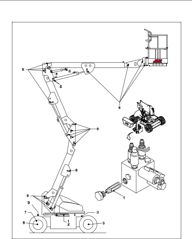
For machine identification, a serial number plate is affixed to the left rear of frame, in front of left rear wheel. If the serial number plate is damaged or missing, the machine
serial number is stamped on the top left side of the frame and the top left side of the turntable. In addition, the serial number is stamped on top of the end of the upper boom, mid boom, and lower boom at the left rear of the booms.
Figure 1-1. Serial Number Locations
3120884 |
– JLG Lift – |
1-5 |
SECTION 1 - SPECIFICATIONS
Figure 1-2. Lubrication Diagram
1-6 |
– JLG Lift – |
3120884 |
SECTION 1 - SPECIFICATIONS
Table 1-8. Lubrication Chart
|
|
|
Number/Type |
|
|
|
Interval |
Hours |
|
||||
|
Components |
|
Capacity |
Lube |
|
|
|
|
Comments |
||||
|
|
Lube Points |
3 Months |
6 Months |
1 Year |
2 Years |
|||||||
|
|
|
|
|
|
|
|||||||
|
|
|
|
|
|
|
|
|
150 hrs |
300 hrs |
600 hrs |
1200 hrs |
|
|
|
|
|
|
|
|
|
|
|
|
|
|
|
|
|
|
|
|
|
|
|
|
|
|
|
||
Lubrication |
|
|
|
|
|
|
|
|
|
|
|
||
|
|
|
|
|
|
|
|
|
|
|
|
||
1 |
Swing Bearing |
|
1 Grease Fitting or by |
|
A/R |
MPG |
X |
|
|
|
More frequent lubrication intervals may be |
||
|
|
|
brush |
|
|
|
|
|
|
|
required |
||
|
|
|
|
|
|
|
|
|
|
|
|
||
2 |
Swing Bearing / |
|
Spray On |
|
A/R |
Mobiltac |
X |
|
|
|
More frequent lubrication intervals may be |
||
|
Worm Gear Teeth* |
|
|
|
|
|
|
375NC |
|
|
|
|
required. |
|
|
|
|
|
|
|
|
|
|
|
|||
3 |
Hydraulic Fluid (Oil) |
|
Fill Cap |
15 liters (tank) |
HO |
|
|
|
X |
Check oil every 10 hours of operation. |
|||
|
|
|
|
|
|
|
|
|
|
|
|
|
Change oil every 1200 hours of operation. |
|
|
|
|
|
|
|
|
|
|
|
|
||
4 |
Hydraulic Filter |
|
N/A |
|
N/A |
N/A |
|
X |
|
|
Replace filter element after first 50 hours and |
||
|
|
|
|
|
|
|
|
|
|
|
|
|
every 300 hours thereafter.** |
|
|
|
|
|
|
|
|
|
|
|
|||
5 |
Wheel Drive Hub |
|
Fill Plug/Half Full |
0.5 liter (1/2 Full) |
EPGL |
|
|
|
X |
Check oil level at side plug on hub daily. |
|||
|
|
|
|
|
|
|
|
|
|
|
|
|
Change after first 150 hours then every 1200 |
|
|
|
|
|
|
|
|
|
|
|
|
|
hours of operation. |
|
|
|
|
|
|
|
|
|
|
|
|
||
6 |
Wheel Bearing |
|
Repack |
|
A/R |
MPG |
|
|
|
X |
|
||
|
|
|
|
|
|
|
|
|
|
|
|
||
7 |
Spindles/Bushing |
|
N/A |
|
A/R |
LL |
At Spindle/Bushing Replacement |
Coat I.D. of bushings prior to installing king |
|||||
|
|
|
|
|
|
|
|
|
|
|
|
|
pins. |
|
|
|
|
|
|
|
|
|
|||||
8 |
Boom Pivot Pins/ |
|
N/A |
|
A/R |
LL |
At boom pivot pins/bushing replacement |
Coat I.D. of bushings prior to installing pins. |
|||||
|
Bushing |
|
|
|
|
|
|
|
|
|
|
|
|
|
|
|
|
|
|
|
|
|
|
|
|||
9 |
Engine |
|
Fill Cap |
Refer to Engine |
EO |
|
|
|
|
Check daily. Change in accordance with |
|||
|
|
|
|
|
|
|
Manual |
|
|
|
|
|
engine manual. |
|
|
|
|
|
|
|
|
|
|
|
|
|
|
NOTES: |
|
|
|
|
|
|
|
|
|
|
KEY TO LUBRICANTS |
||
|
|
|
|
|
|
|
|
|
|
|
|
|
|
Lubrication intervals are based on machine operation under normal conditions. For machines used in multi shift operations and/or exposed to hostile |
EO |
Engine Oil |
|||||||||||
environments or conditions, lubrication frequencies must be increased accordingly. |
|
|
|
|
EPGL |
Extreme Pressure Gear Lube |
|||||||
|
|
|
|
|
|
|
|
|
|
|
|
HO |
Hydraulic Fluid (Mobil DTE-11M) |
|
|
|
|
|
|
|
|
|
|
|
|
MPG |
Multi-Purpose Grease |
|
|
|
|
|
|
|
|
|
|
|
|
||
* If necessary install grease fittings into worm gear housing and grease bearings. |
|
|
|
|
LL |
Synthetic Lithium Lubricant |
|||||||
|
|
|
|
|
|
|
|
|
|
|
|
|
|
|
|
|
|
|
|
|
|
|
|
|
|
|
|
DO NOT OVERGREASE BEARINGS. OVERGREASING BEARINGS WILL RESULT IN
BLOWING OUTER SEAL IN HOUSING.
** Under certain conditions, it may be necessary to replace the hydraulic filter on a more frequent basis. A common symptom of a dirty filter is sluggishness experienced in hydraulic functions.
3120884 |
– JLG Lift – |
1-7 |

SECTION 1 - SPECIFICATIONS
Figure 1-3. Torque Chart
|
|
|
|
|
|
|
|
|
|
|
|
|
|
|
|
|
|
|
|
|
|
|
|
|
|
|
|
|
|
|
|
|
|
|
|
|
|
|
|
|
|
|
|
|
|
|
|
|
|
|
|
|
|
|
|
|
|
|
|
|
|
|
|
|
|
|
|
|
|
|
|
|
|
|
|
|
|
|
|
|
|
|
|
|
|
|
|
|
|
|
|
|
|
|
|
|
|
|
|
1-8 |
|
|
|
|
|
|
|
|
|
|
|
– JLG Lift – |
3120884 |
|||||||||||
|
|
|
|
|
|
|
|
|
|
|
||||||||||||||
|
|
|
|
|
|
|
|
|
|
|
||||||||||||||

SECTION 2 - PROCEDURES
SECTION 2. PROCEDURES
2.1GENERAL
This section provides information necessary to perform maintenance on the aerial platform. Descriptions, techniques and specific procedures are designed to provide the safest and most efficient maintenance for use by personnel responsible for ensuring the correct installation and operation of machine components and systems.
WHEN AN ABNORMAL CONDITION IS NOTED AND PROCEDURES
CONTAINED HEREIN DO NOT SPECIFICALLY RELATE TO THE NOTED IRREGULARITY, WORK SHOULD BE STOPPED AND
TECHNICALLY QUALIFIED GUIDANCE OBTAINED BEFORE WORK IS RESUMED.
The maintenance procedures included consist of servicing and component removal and installation, disassembly, and assembly, inspection, lubrication and cleaning. Information on any special tools or test equipment is also provided where applicable.
2.2SERVICING AND MAINTENANCE GUIDELINES
General
The following information is provided to assist you in the use and application of servicing and maintenance procedures contained in this chapter.
Safety and Workmanship
Your safety and that of others is the first consideration when engaging in the maintenance of equipment. Always be conscious of weight. Never attempt to move heavy parts without the aid of a mechanical device. Do not allow heavy objects to rest in an unstable position. When raising a portion of the equipment, ensure that adequate support is provided.
Cleanliness
1.The most important single item in preserving the long service life of a machine is to keep dirt and foreign materials out of the vital components. Precautions have been taken to safeguard against this. Shields, covers, seals and filters are provided to keep oil supplies clean; however, these items must be maintained on a scheduled basis in order to function properly.
2.At any time when hydraulic oil lines are disconnected, clear adjacent areas as well as the openings
and fittings themselves. As soon as a line or component is disconnected, cap or cover all openings to prevent entry of foreign matter.
3.Clean and inspect all parts during servicing or maintenance, and assure that all passages and openings are unobstructed. Cover all parts to keep them clean. Be sure all parts are clean before they are installed. New parts should remain in their containers until they are ready to be used.
Component Removal and Installation
1.Use adjustable lifting devices, whenever possible, if mechanical assistance is required. All slings (chains, cables, etc.) should be parallel to each other and as near perpendicular as possible to top of part being lifted.
2.Should it be necessary to remove a component on an angle, keep in mind that the capacity of an eyebolt or similar bracket lessens, as the angle between the supporting structure and the component becomes less than 90 degrees.
3.If a part resists removal, check to see whether all nuts, bolts, cables, brackets, wiring, etc. have been removed and that no adjacent parts are interfering.
Component Disassembly and Reassembly
When disassembling or reassembling a component, complete the procedural steps in sequence. Do not partially disassemble or assemble one part, then start on another. Always recheck your work to assure that nothing has been overlooked. Do not make any adjustments, other than those recommended, without obtaining proper approval.
Pressure Fit Parts
When assembling pressure fit parts, use an “anti-seize” or molybdenum disulfide base compound to lubricate the mating surface.
3120884 |
– JLG Lift – |
2-1 |

SECTION 2 - PROCEDURES
Bearings |
|
Hydraulic Lines and Electrical Wiring |
1.When a bearing is removed, cover it to keep out dirt and abrasives. Clean bearings in nonflammable cleaning solvent and allow to drip dry. Compressed air can be used but do not spin the bearing.
2.Discard bearings if the races and balls (or rollers) are pitted, scored or burned.
3.If bearing is found to be serviceable, apply a light coat of oil and wrap it in clean (waxed) paper. Do not unwrap reusable or new bearings until they are ready to be installed.
4.Lubricate new or used serviceable bearings before installation. When pressing a bearing into a retainer or bore, apply pressure to the outer race. If the bearing is to be installed on a shaft, apply pressure to the inner race.
Gaskets
Check that holes in gaskets align with openings in the mating parts. If it becomes necessary to hand fabricate a gasket, use gasket material or stock of equivalent material and thickness. Be sure to cut holes in the right location as blank gaskets can cause serious system damage.
Bolt Usage and Torque Application
1.Use bolts of proper length. A bolt which is too long will bottom before the head is tight against its related part. If a bolt is too short, there will not be enough thread area to engage and hold the part properly. When replacing bolts, use only those having the same specifications of the original, or one which is equivalent.
2.Unless specific torque requirements are given within the text, standard torque values should be used on heat treated bolts, studs and steel nuts, in accordance with recommended shop practices.
Clearly mark or tag hydraulic lines and electrical wiring, as well as their receptacles, when disconnecting or removing them from the unit. This will assure that they are correctly reinstalled.
Hydraulic System
1.Keep the system clean. If evidence of metal or rubber particles are found in the hydraulic system, drain and flush the entire system.
2.Disassemble and reassemble parts on clean work surface. Clean all metal parts with non-flammable cleaning solvent. Lubricate components, as required, to aid assembly.
Lubrication
Service applicable components with the amount, type, and grade of lubricant recommended in this manual, at the specified interval. When recommended lubricants are not available, consult your local supplier for an equivalent that meets or exceeds the specifications listed.
Batteries
Clean batteries using a non-metallic brush and a solution of baking soda and water. Rinse with clean water. After cleaning, thoroughly dry batteries and coat terminals with an anti-corrosion compound.
Lubrication and Servicing
Components and assemblies requiring lubrication and servicing are shown in Lubrication Chart.
2-2 |
– JLG Lift – |
3120884 |
SECTION 2 - PROCEDURES
2.3 LUBRICATION INFORMATION
Hydraulic System
1.The primary enemy of a hydraulic system is contamination. Contaminants enter the system by various means, e.g.; inadequate hydraulic oil, allowing moisture, grease, filings, sealing components, sand, etc. to enter when performing maintenance, or by permitting the pump to cavitate due to insufficient system warm-up.
2.The design and manufacturing tolerances of the component working parts are very close, therefore, even the smallest amount of dirt or foreign matter entering a system can cause wear or damage to the components and generally results in faulty operation. Every precaution must be taken to keep hydraulic oil clean, including reserve oil in storage. Hydraulic system filters should be checked, cleaned, and/or replaced at the specified intervals required in Section 1. Always examine filters for evidence of metal particles.
3.Cloudy oils indicate a high moisture content which permits organic growth, resulting in oxidation or corrosion. If this condition occurs, the system must be drained, flushed, and refilled with clean oil.
4.It is not advisable to mix oils of different brands or types, as they may not contain the same required additives or be of comparable viscosities. Good grade mineral oils, with viscosities suited to the ambient temperatures in which the machine is operating, are recommended for use.
NOTE: Metal particles may appear in the oil or filters of new machines due to the wear-in of meshing components.
Hydraulic Oil
1.Refer to Section 1 for recommendations for viscosity ranges.
2.JLG recommends Mobil DTE-11 Hydraulic Oil, which has an SAE viscosity of 10W and a viscosity index of 140.
NOTE: Start-up of hydraulic system with oil temperatures below -29 degrees C. is not recommended. If it is necessary to start the system in a sub-zero environment, it will be necessary to heat the oil with a low density 100VAC heater to a minimum temperature of -29 degrees C.
3.Some machines may be specially equipped with Mobil EAL224H biodegradable and non-toxic hydraulic oil. This oil is vegetable oil based and pos-
sesses the same antiwear and rust protection characteristics as mineral oils, but will not adversely affect ground water or the environment when spilled or leaked in small amounts. Mobil EAL224H has a viscosity of 34 cST at 40° C and a viscosity index of 213. The operating range of this oil is -18° C to +83° C.
IT IS RECOMMENDED THAT MOBIL EAL224H HYDRAULIC OIL BE STORED ABOVE FREEZING (0 C) AS THE OIL MAY APPEAR CLOUDY AFTER EXPOSURE TO LOW TEMPERATURES FOR EXTENDED PERIODS OF TIME. THE CLOUDINESS WILL DISAPPEAR
WHEN THE OIL IS WARMED TO AT LEAST 10 C AND AGITATED. DO
NOT ATTEMPT TO "THIN" THE OIL WITH NO.2 DIESEL FUEL. FOR BEST RESULTS, STORE THE OIL ABOVE FREEZING.
NOTE: Accidentally mixing Mobil EAL224H hydraulic oil with other mineral oils will cause no loss of performance characteristics. However, biodegradability may be reduced and toxicity may be increased, depending on the oil and level of contamination.
Changing Hydraulic Oil
1.Use of any of the recommended hydraulic oils eliminates the need for changing the oil on a regular basis. However, filter elements must be changed after the first 50 hours of operation and every 300 hours thereafter. If it is necessary to change the oil, use only those oils meeting or exceeding the specifications appearing in this manual. If unable to obtain the same type of oil supplied with the machine, consult local supplier for assistance in selecting the proper equivalent. Avoid mixing petroleum and synthetic base oils. JLG Industries recommends changing the hydraulic oil every two years.
2.Use every precaution to keep the hydraulic oil clean. If the oil must be poured from the original container into another, be sure to clean all possible contaminants from the service container. Always clean the mesh element of the filter and replace the cartridge any time the system oil is changed.
3.While the unit is shut down, a good preventive maintenance measure is to make a thorough inspection of all hydraulic components, lines, fittings, etc., as well as a functional check of each system, before placing the machine back in service.
3120884 |
– JLG Lift – |
2-3 |

SECTION 2 - PROCEDURES
Lubrication Specifications
Specified lubricants, as recommended by the component manufacturers, are always the best choice, however, multi-purpose greases usually have the qualities which meet a variety of single purpose requirements. Should any question arise regarding the use of greases in maintenance stock, consult your local supplier for evaluation. Refer to Section 1 for an explanation of the lubricant key designations appearing in the Lubrication Chart.
2.4BATTERY MAINTENANCE AND CHARGING
Battery Maintenance, Quarterly
1.Open battery compartment cover to allow access to battery terminals and vent caps.
WHEN ADDING WATER TO BATTERIES, ADD WATER UNTIL ELEC-
TROLYTE COVERS PLATES. DO NOT CHARGE BATTERIES UNLESS ELECTROLYTE COVERS THE PLATES.
NOTE: When adding distilled water to batteries, non-metallic containers and/or funnels must be used.
To avoid electrolyte overflow, add distilled water to batteries after charging.
When adding water to the battery, fill only to level indicated or 9.5 mm above separators.
2.Remove all vent caps and inspect electrolyte level of each cell. Electrolyte level should be to the ring approximately one inch from top of battery. Fill batteries with distilled water only. Replace and secure all vent caps.
3.Remove battery cables from each battery post one at a time, negative first. Clean cables with acid neutralizing solution (e.g. baking soda and water or ammonia) and wire brush. Replace cables and/or cable clamp bolts as required.
4.Clean battery post with wire brush then re-connect cable to post. Coat non-contact surfaces with mineral grease or petroleum jelly.
5.When all cables and terminal posts have been cleaned, ensure all cables are properly positioned and do not get pinched. Close battery compartment cover.
6.Start hydraulic system and ensure that it functions properly.
Optional On Board Generator
EXHAUST GAS HAZARD. RUN THE GENERATOR IN A WELL VEN-
TILATED AREA ONLY.
WHEN THE GENERATOR ENABLE CONTROL LOCATED IN THE
PLATFORM CONTROL BOX IS IN THE ON POSITION AND THE GROUND EMERGENCY STOP SWITCH IS ON (PULLED OUT), THE
GENERATOR WILL START AUTOMATICALLY WHEN THE BAT-
TERIES REACH A LOW-CHARGE STATE, AUTOMATICALLY
CHARGING THE BATTERIES. THE GENERATOR WILL ALSO
AUTOMATICALLY START IF THE GENERATOR START BATTERY IS LOW.
2-4 |
– JLG Lift – |
3120884 |
SECTION 2 - PROCEDURES
Figure 2-1. On Board Generator
3120884 |
– JLG Lift – |
2-5 |
SECTION 2 - PROCEDURES
NOTE: The engine will automatically shut down under the following conditions:
High Engine Oil Temperature
Low Engine Oil Pressure
Engine Overspeed
Generator Overvoltage
Batteries fully charged
TO AVOID INJURY FROM AN EXPLOSION, DO NOT SMOKE OR ALLOW SPARKS OR A FLAME NEAR BATTERY DURING SERVICING. ALWAYS WEAR EYE AND HAND PROTECTION WHEN SER-
VICING BATTERIES.
Battery Charging (On Board Charger)
1.For maximum battery life:
a.Avoid completely discharging the batteries.
b.Fully charge the batteries each day the machine is used.
c.Charge the batteries at available times between charging.
d.Be sure the battery fluid covers the battery plates before charging, but to avoid overflow, do not top off the fluid level until charging.
2.To charge the batteries, connect the charger to a 115 volt source with a 15 amp minimum capacity.
3.The Charger will shut off automatically when the batteries are fully charged.
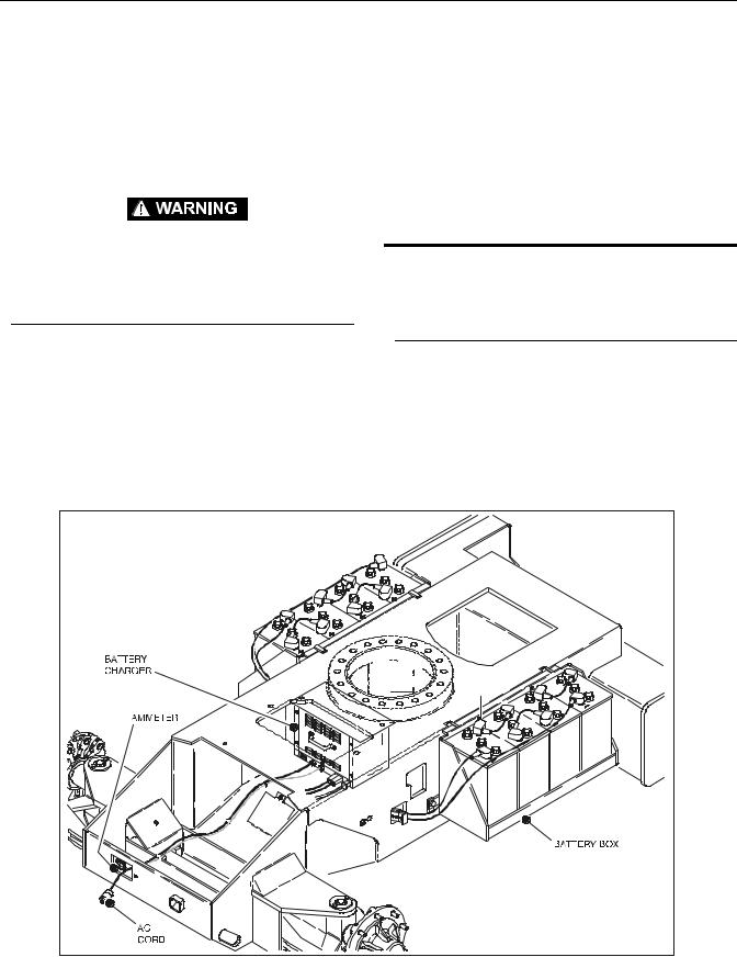
4.The charge cycle is complete when the ammeter reads 0 amps. Any reading indicates the charge cycle is not complete.
5.Depleted batteries will take approximately 17 hours to charge.
2.5CYLINDERS - THEORY OF OPERATION
Upper Boom Lift, Mid Boom Lift, Lower
Boom Lift, Telescope, Slave, Master, Rotator,
and Steer
A double acting cylinder is one that requires oil flow to operate the cylinder rod in both directions. Directing oil (by actuating the corresponding control valve to the piston side of the cylinder) forces the piston to travel toward the rod end of the barrel, extending the cylinder rod (piston attached to rod). When the oil flow is stopped, movement of the rod will stop. By directing oil to the rod side of the cylinder, the piston will be forced in the opposite direction and the cylinder rod will retract.
Figure 2-2. Batteries and Battery Charger
2-6 |
– JLG Lift – |
3120884 |
SECTION 2 - PROCEDURES
Holding valves are used in the Lift circuits to prevent retraction of the cylinder rod should a hydraulic line rupture or leak develop between the cylinder and its related control valve.
WHEN WORKING ON THE UPPER BOOM LIFT CYLINDER RAISE THE UPPER BOOM TO HORIZONTAL AND PLACE A BOOM PROP APPROXIMATELY 2.5 CM BELOW THE MAIN BOOM. IF WORKING
ON LOWER BOOM LIFT CYLINDER, RAISE LOWER BOOM HALF-
2.6CYLINDER CHECKING PROCEDURES WAY, FULLY ELEVATE UPPER BOOM AND ATTACH OVERHEAD
NOTE: Cylinder checks must be performed any time a cylinder component is replaced or when improper system operation is suspected.
Cylinder Without Counterbalance Valves
(Steer, Master, and Rotate)
1.Using all applicable safety precautions, activate hydraulic system and fully extend cylinder to be checked. Shut down hydraulic system.
2.Carefully disconnect hydraulic hose from retract port of cylinder. There will be initial weeping of hydraulic fluid which can be caught in a suitable container. After initial discharge, there should be no further leakage from the retract port.
3.Activate hydraulic system, and activate cylinder extend function.
4.If cylinder retract port leakage is less than 6-8 drops per minute, carefully reconnect hose to retract port and retract cylinder. If leakage continues at a rate of 6-8 drops per minute or more, cylinder repairs must be made.
5.With cylinder fully retracted, shut down motor and carefully disconnect hydraulic hose from cylinder extend port.
6.Activate hydraulic system and activate cylinder retract function. Check extend port for leakage.
7.If extend port leakage is less than 6-8 drops per minute, carefully reconnect hose to extend port, then activate cylinder through one complete cycle and check for leaks. If leakage continues at a rate of 6-8 drops per minute or more, cylinder repairs must be made.
Cylinders With Single Counterbalance Valve
(Upper Lift Cylinder)
OPERATE ALL FUNCTIONS FROM GROUND CONTROL STATION ONLY.
1.Using all applicable safety precautions, activate hydraulic system.
CRANE TO THE UPRIGHT FOR SUPPORT, LEAVING APPROXI-
MATELY 2.5 CM OF SLACK IN CHAIN OR SLING FOR TEST PUR-
POSES.
2.After completing the above, shut down hydraulic system and allow machine to sit for 10-15 minutes. This is done to relieve pressure in the hydraulic lines. Carefully remove hydraulic hoses from appropriate cylinder port block.
3.There will be initial weeping of hydraulic fluid, which can be caught in a suitable container. After the initial discharge, there should not be any further leakage from the ports. If leakage continues at a rate of 6-8 drops per minute or more, the following cylinder repairs must be made. If the retract port is leaking, the piston is leaking, the piston seals are defective and must be replaced. If the extend port is leaking, the counterbalance is defective and must be replaced.
4.If no repairs are necessary or when repairs have been made, carefully reconnect hydraulic hoses to the appropriate ports.
5.Remove boom prop/overhead crane, activate hydraulic system and run cylinder through complete cycle to check for leaks and operation.
Cylinders With Dual Counterbalance Valve
(Lower Lift, Mid Lift, Telescope, and Slave
Cylinders)
OPERATE ALL FUNCTIONS FROM GROUND CONTROL STATION
ONLY.
1.Using all applicable safety precautions, activate hydraulic system.
WHEN WORKING ON THE UPPER BOOM LIFT CYLINDER RAISE THE UPPER BOOM TO HORIZONTAL AND PLACE A BOOM PROP APPROXIMATELY 2.5 CM BELOW THE MAIN BOOM. IF WORKING ON LOWER BOOM LIFT CYLINDER, RAISE LOWER BOOM HALF-
WAY, FULLY ELEVATE UPPER BOOM AND ATTACH OVERHEAD
CRANE TO THE UPRIGHT FOR SUPPORT, LEAVING APPROXI-
MATELY 2.5 CM OF SLACK IN CHAIN OR SLING FOR TEST PUR-
POSES.
3120884 |
– JLG Lift – |
2-7 |
SECTION 2 - PROCEDURES
2.When working on the platform slave cylinder, stroke platform slave level cylinder forward until platform sits at a 45 degree angle.
3.After completing the above, shut down hydraulic system and allow machine to sit for 10-15 minutes. This is done to relieve pressure in the hydraulic lines. Carefully remove hydraulic hoses from appropriate cylinder port block.
4.There will be initial weeping of hydraulic fluid, which can be caught in a suitable container. After the initial discharge, there should not be any further leakage from the ports. If leakage continues at a rate of 6-8 drops per minute or more, the following cylinder repairs must be made. If the retract port is leaking, the piston is leaking, the piston seals are defective and must be replaced. If the extend port is leaking, the counterbalance is defective and must be replaced.
5.To check piston seals, carefully remove the counterbalance valve from the retract port. After initial discharge there should not be any further leakage from the ports. If leakage occurs at a rate of 6-8 drops per minute or more, the piston seals are defective and must be replaced.
6.If no repairs are necessary or when repairs have been made, carefully reconnect hydraulic hoses to the appropriate ports.
7.Remove boom prop/overhead crane, activate hydraulic system and run cylinder through complete cycle to check for leaks and operation.
2.7CYLINDER REPAIR
NOTE: The following are general procedures that apply to all of the cylinders on this machine. Procedures that apply to a specific cylinder will be so noted.
Disassembly
DISASSEMBLY OF THE CYLINDER SHOULD BE PERFORMED ON
A CLEAN WORK SURFACE IN A DIRT FREE WORK AREA.
1.Connect a suitable auxiliary hydraulic power source to the cylinder port block fitting.
DO NOT FULLY EXTEND CYLINDER TO THE END OF STROKE.
RETRACT CYLINDER SLIGHTLY TO AVOID TRAPPING PRES-
SURE.
2.Operate the hydraulic power source and extend the cylinder. Shut down and disconnect the power
source. Adequately support the cylinder rod, if applicable.
3.If applicable, remove the cartridge-type holding valve and fittings from the cylinder port block. Discard o-rings.
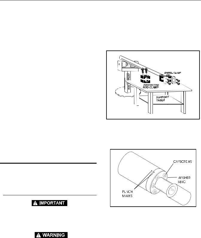
4.Place the cylinder barrel into a suitable holding fixture.
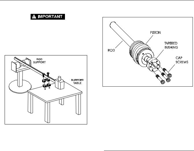
Figure 2-3. Cylinder Barrel Support
5.Mark cylinder head and barrel with a center punch for easy realignment. Using an allen wrench, loosen the cylinder head retainer cap screws, and remove cap screws from cylinder barrel.
Figure 2-4. Capscrew Removal
NOTE: Steps 6 applies only to the lower lift and telescope cylinders.
6.Using a spanner wrench, loosen the end cap or head retainer, and remove from cylinder barrel.
7.Attach a suitable pulling device to the cylinder rod port block end or cylinder rod end, as applicable.
2-8 |
– JLG Lift – |
3120884 |
SECTION 2 - PROCEDURES
EXTREME CARE SHOULD BE TAKEN WHEN REMOVING THE CYLINDER ROD, HEAD, AND PISTON. AVOID PULLING THE ROD OFF-
CENTER, WHICH COULD CAUSE DAMAGE TO THE PISTON AND
CYLINDER BARREL SURFACES.
8.With the barrel clamped securely, apply pressure to the rod pulling device and carefully withdraw the complete rod assembly from the cylinder barrel.
Figure 2-5. Cylinder Rod Support
9.Using suitable protection, clamp the cylinder rod in a vise or similar holding fixture as close to the piston as possible.
10.Loosen and remove the cap screw(s), if applicable, which attach the tapered bushing to the piston.
11.Insert the cap screw(s) in the threaded holes in the outer piece of the tapered bushing. Progressively tighten the cap screw(s) until the bushing is loose on the piston.
12. Remove the bushing from the piston.
Figure 2-6. Tapered Bushing Removal
13.Screw the piston CCW, by hand, and remove the piston from cylinder rod.
14.Remove and discard the piston o-rings, seal rings, and backup rings.
15.Remove piston spacer, if applicable, from the rod.
16.Remove the rod from the holding fixture. Remove the cylinder head gland and retainer plate, if applicable. Discard the o-rings, back-up rings, rod seals, and wiper seals.
Cleaning and Inspection
1.Clean all parts thoroughly in an approved cleaning solvent.
2.Inspect the cylinder rod for scoring, tapering, ovality, or other damage. If necessary, dress rod with Scotch Brite or equivalent. Replace rod if necessary.
3.Inspect threaded portion of rod for excessive damage. Dress threads as necessary.
4.Inspect inner surface of cylinder barrel tube for scoring or other damage. Check inside diameter for tapering or ovality. Replace if necessary.
5.Inspect threaded portion of barrel for damage. Dress threads as necessary.
6.Inspect piston surface for damage and scoring and for distortion. Dress piston surface or replace piston as necessary.
7.Inspect threaded portion of piston for damage. Dress threads as necessary.
8.Inspect seal and o-ring grooves in piston for burrs and sharp edges. Dress applicable surfaces as necessary.
3120884 |
– JLG Lift – |
2-9 |
SECTION 2 - PROCEDURES
9.Inspect cylinder head inside diameter for scoring or other damage and for ovality and tapering. Replace as necessary.
10.Inspect threaded portion of head for damage. Dress threads as necessary.
11.Inspect seal and o-ring grooves in head for burrs and sharp edges. Dress applicable surfaces as necessary.
12.Inspect cylinder head outside diameter for scoring or other damage and ovality and tapering. Replace as necessary.
13.If applicable, inspect rod and barrel bearings for signs of correct excessive wear or damage. Replace as necessary.
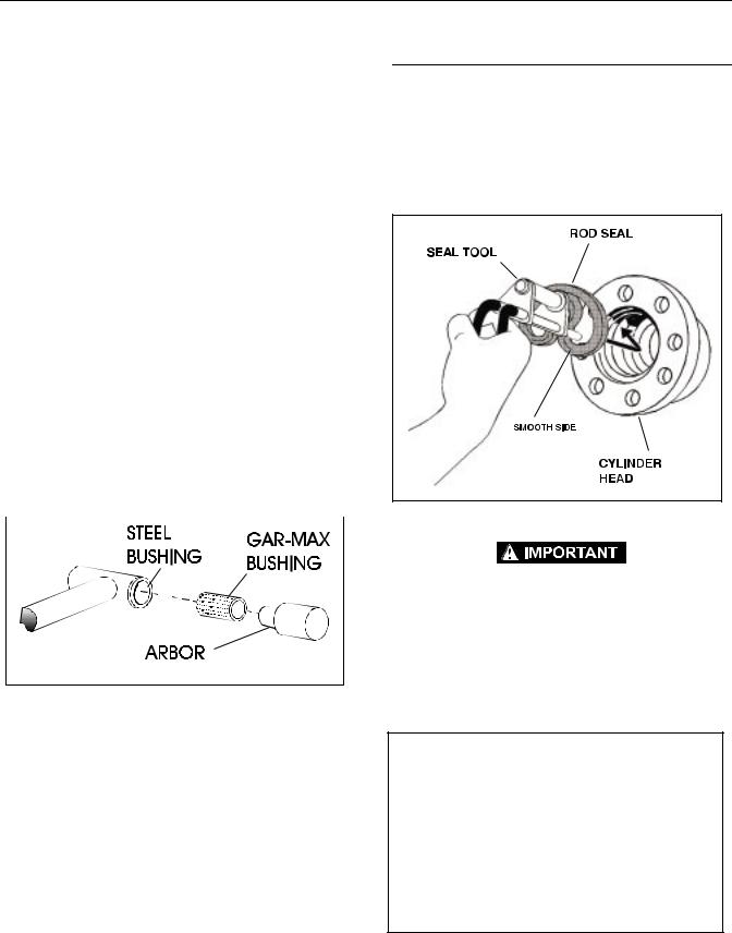
a.Thoroughly clean hole, (steel bushing) of burrs, dirt etc. to facilitate bearing installation.
b.Inspect steel bushing for wear or other damage. If steel bushing is worn or damaged, rod/barrel must be replaced.
c.Lubricate inside of the steel bushing with WD40 prior to bearing installation.
d.Using an arbor of the correct size, carefully press the bearing into steel bushing.
NOTE: Install pin into the Gar-Max bearing dry. Lubrication is not required with nickel plated pins and bearings.
Figure 2-7. Gar-Max Bearing Installation
14.Inspect travel limiting collar or spacer for burrs and sharp edges. If necessary, dress inside diameter surface with Scotch Brite or equivalent.
15.If applicable, inspect port block fittings and holding valve. Replace as necessary.
16.Inspect the oil ports for blockage or the presence of dirt or other foreign material. Repair as necessary.
17.If applicable, inspect piston rings for cracks or other damage. Replace as necessary.
Assembly
NOTE: Prior to cylinder assembly, ensure that the proper cylinder seal kit is used. See your JLG Parts Manual.
Apply a light film of hydraulic oil to all components prior to assembly.
1.A special tool is used to install a new rod seal into the applicable cylinder head gland groove.
Figure 2-8. Rod Seal Installation
WHEN INSTALLING "POLY-PAK" PISTON SEALS, ENSURE SEALS ARE INSTALLED PROPERLY. REFER TO WIPER SEAL INSTALLA-
TION FOR CORRECT SEAL ORIENTATION. IMPROPER SEAL
INSTALLATION COULD RESULT IN CYLINDER LEAKAGE AND
IMPROPER CYLINDER OPERATION.
2.Use a soft mallet to tap a new wiper seal into the applicable cylinder head gland groove. Install a new wear ring into the applicable cylinder head gland groove.
Figure 2-9. Wiper Seal Installation
2-10 |
– JLG Lift – |
3120884 |
SECTION 2 - PROCEDURES
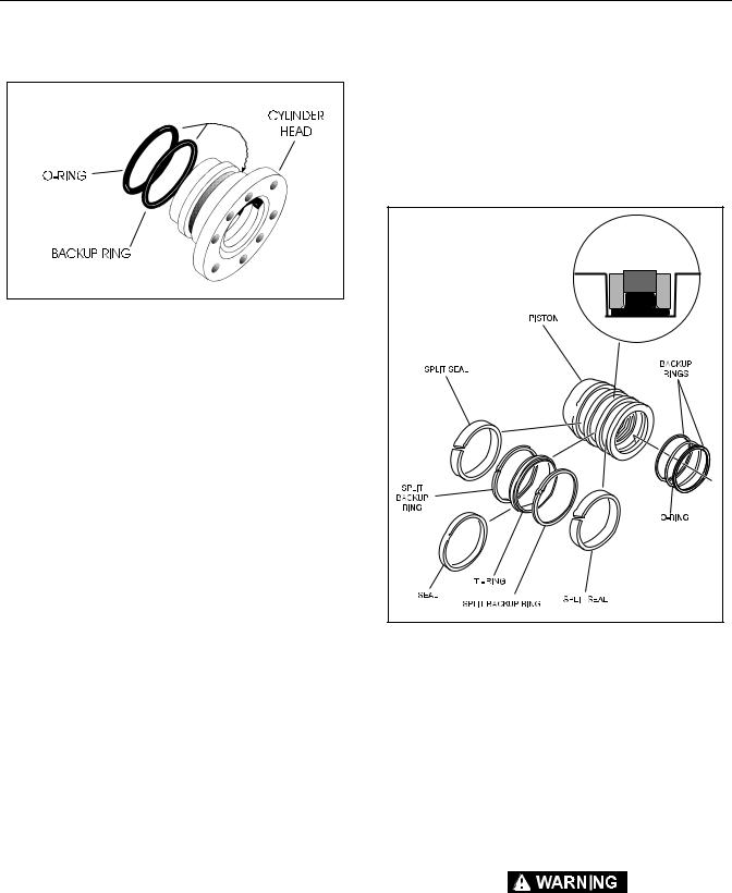
3.Place a new o-ring and back-up seal in the applicable outside diameter groove of the cylinder head.
Figure 2-10. Installation of Head Seal Kit
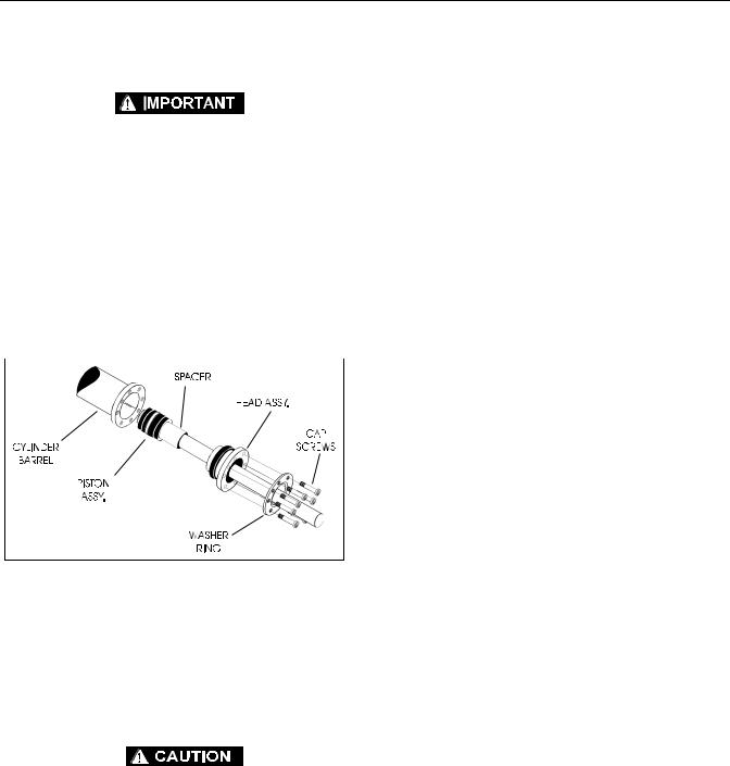
4.Install washer ring onto rod, carefully install the head gland on the rod, ensuring that the wiper and rod seals are not damaged or dislodged. Push the head along the rod to the rod end, as applicable.
5.Carefully slide the piston spacer on the rod.
6.If applicable, correctly place new o-ring in the inner piston diameter groove. (The backup ring side facing the O-ring is grooved.)
7.If applicable, correctly place new seals and guide lock rings in the outer piston diameter groove. (A tube, with I.D. slightly larger than the O.D.of the piston is recommended to install the solid seal.)
NOTE: The backup rings for the solid seal have a radius on one side. This side faces the solid seal.(See magnified insert in Figure 2-11.)The split of seals and backup rings are to be positioned so as not to be in alignment with each other.
Figure 2-11. Piston Seal Kit Installation
8.Using suitable protection, clamp the cylinder rod in a vise or similar holding fixture as close to piston as possible.
9.Carefully thread the piston on the cylinder rod hand tight, ensuring that the o-ring and back-up rings are not damaged or dislodged.
10.Thread piston onto rod until it abuts the spacer end and install the tapered bushing.
NOTE: When installing the tapered bushing, piston and mating end of rod must be free of oil.
WHEN REBUILDING THE STEER, LOWER LIFT, LEVEL CYLINDER,
OR UPPER LIFT CYLINDER, APPLY LOCTITE #242 TO TAPERED
BUSHING BOLTS, THEN TIGHTEN SECURELY.
3120884 |
– JLG Lift – |
2-11 |

SECTION 2 - PROCEDURES
11.Assemble the tapered bushing loosely into the piston and insert JLG capscrews (not vendor capscrews) through the drilled holes in the bushing and into the tapped holes in the piston.
b.Tap each space once; this means the tapered bushing is tapped 3 times as there are 3 spaces between the capscrews.
Figure 2-12. Tapered Bushing Installation
12.Tighten the capscrews evenly and progressively in rotation to the specified torque value. (See Table 2-1, Cylinder Head and Tapered Bushing Torque Specifications.)
13.After the screws have been torqued, tap the tapered bushing with a hammer (500 to 750 gram) and brass shaft (approximately 19 mm in diameter) as follows;
a.Place the shaft against the cylinder rod and in contact with the bushing in the spaces between the capscrews.
Figure 2-13. Seating the Tapered Bearing
14.Retorque the capscrews evenly and progressively in rotation to the specified torque value. (See Table 2-1, Cylinder Head and Tapered Bushing Torque Specifications.)
15.Remove the cylinder rod from the holding fixture.
16.Place new guide locks and seals in the applicable outside diameter grooves of the cylinder piston. (See Figure 2-11., Piston Seal Kit Installation)
Figure 2-14. Poly-Pak Piston Seal Installation
2-12 |
– JLG Lift – |
3120884 |
SECTION 2 - PROCEDURES
17.Position the cylinder barrel in a suitable holding fixture.
EXTREME CARE SHOULD BE TAKEN WHEN INSTALLING THE CYLINDER ROD, HEAD, AND PISTON. AVOID PULLING THE ROD OFF-CENTER, WHICH COULD CAUSE DAMAGE TO THE PISTON AND CYLINDER BARREL SURFACES.
18.With barrel clamped securely, and while adequately supporting the rod, insert the piston end into the barrel cylinder. Ensure that the piston loading o-ring and seal ring are not damaged or dislodged.
19.Continue pushing the rod into the barrel until the cylinder head gland can be inserted into the barrel cylinder.
20.Secure the cylinder head gland using the washer ring and socket head bolts.
Figure 2-15. Rod Assembly Installation
21.After the cylinder has been reassembled, the rod should be pushed all the way in (fully retracted) prior to the reinstallation of any holding valve or valves.
22.If applicable, install the cartridge-type holding valve and fittings in the rod port block, using new o-rings as applicable. (See Table 2-3, Holding Valve Torque Specifications).
IF THE CYLINDER IS TO BE TESTED PRIOR TO INSTALLATION ON
THE MACHINE, EXTREME CARE SHOULD BE USED TO INSURE
THAT THE OUTER END OF THE ROD IS SUPPORTED. USE EITHER A TRAVELING OVERHEAD HOIST, FORK-LIFT, OR OTHER MEANS TO SUPPORT THE OVERHANGING WEIGHT OF THE
EXTENDING ROD.
Table 2-1.Cylinder Head and Tapered Bushing Torque
Specifications
|
Description |
Head Torque Value |
|
Tapered Bushing |
|
|||
|
|
|
(Wet) |
|
Torque Value (Wet) |
|
||
|
|
|
|
|
|
|||
|
|
|
|
|
|
|
|
|
|
E.A.R. Cylinder |
|
|
30 ft. lbs |
|
|
5 ft. lbs. |
|
|
|
|
(41 Nm) |
|
|
(7 Nm) |
|
|
|
|
|
|
|
|
|
||
|
|
|
|
|
|
|
|
|
|
Level Cylinder (M45AJ) |
|
|
30 ft. lbs |
|
|
5 ft. lbs. |
|
|
|
|
(41 Nm) |
|
|
(7 Nm) |
|
|
|
|
|
|
|
|
|
||
|
|
|
|
|
|
|
|
|
|
Master Cylinder |
|
|
30 ft. lbs. |
|
|
5 ft. lbs. |
|
|
(M45AJ) |
|
|
(41 Nm) |
|
|
(7 Nm) |
|
|
|
|
|
|
|
|
||
|
Table 2-2. Cylinder Piston Nut Torque Specifications) |
|
||||||
|
|
|
|
|
|
|
|
|
|
|
|
|
Nut Torque |
|
Setscrew |
|
|
|
Description |
|
|
Valve (Wet) |
|
Torque Value |
|
|
|
|
|
|
|
|
|
(Dry) |
|
|
|
|
|
|
|
|
|
|
|
|
|
|
|
|
|
|
|
|
Upper |
|
|
200 ft. lbs. |
|
100 in. lbs. |
|
|
|
Lift Cylinder |
|
|
(270 Nm) |
|
(11 Nm) |
|
|
|
|
|
|
|
|
|
|
|
|
Mid |
|
|
400 ft. lbs. |
|
100 in. lbs. |
|
|
|
Lift Cylinder |
|
|
(542 Nm) |
|
(11 Nm) |
|
|
|
|
|
|
|
|
|
|
|
|
Lower |
|
|
400 ft. lbs. |
|
100 in. lbs. |
|
|
|
Lift Cylinder |
|
|
(542 Nm) |
|
(11 Nm) |
|
|
|
|
|
|
|
|
|
|
|
|
Level Cylinder (M45 A) |
|
80 ft. lbs. |
|
100 in. lbs. |
|
||
|
|
|
|
(108 Nm) |
|
(11 Nm) |
|
|
|
|
|
|
|
|
|
|
|
|
Master Cylinder |
|
|
80 ft. lbs. |
|
100 in. lbs. |
|
|
|
(M45A) |
|
|
(108 Nm) |
|
(11 Nm) |
|
|
|
|
|
|
|
|
|||
|
Table 2-3. Holding Valve Torque Specifications |
|
||||||
|
|
|
|
|
|
|
|
|
|
Description |
|
|
|
Torque Value |
|
||
|
|
|
|
|
|
|
|
|
|
|
|
|
|
|
|||
|
SUN - 7/8 HEX M20 X 1.5 THDS. |
|
|
30-35 ft. lbs. |
|
|||
|
|
|
|
|
|
|
(41-48 Nm) |
|
|
|
|
|
|
|
|||
|
SUN - 1 1/8 HEX 1 -14 UNS THDS. |
|
|
45-50 ft. lbs. |
|
|||
|
|
|
|
|
|
|
(61-68 Nm) |
|
|
|
|
|
|
|
|||
|
SUN - 1 1/4 HEX M36 X 2 THDS. |
|
|
150-160 ft. lbs. |
|
|||
|
|
|
|
|
|
|
(204-217 Nm) |
|
|
|
|
|
|
|
|||
|
RACINE - 1 1/8 HEX 1 1/16 - 12 THDS. |
|
|
50-55 ft. lbs. |
|
|||
|
|
|
|
|
|
|
(68-75 Nm) |
|
|
|
|
|
|
|
|||
|
RACINE - 1 3/8 HEX 1 3/16 - 12 THDS. |
|
|
75-80 ft. lbs. |
|
|||
|
|
|
|
|
|
|
(102-109 Nm) |
|
|
|
|
|
|
|
|||
|
RACINE - 1 7/8 HEX 1 5/8 - 12 THDS. |
|
|
100-110 ft. lbs. |
|
|||
|
|
|
|
|
|
|
(136-149 Nm) |
|
|
|
|
|
|
|
|
|
|
3120884 |
– JLG Lift – |
2-13 |
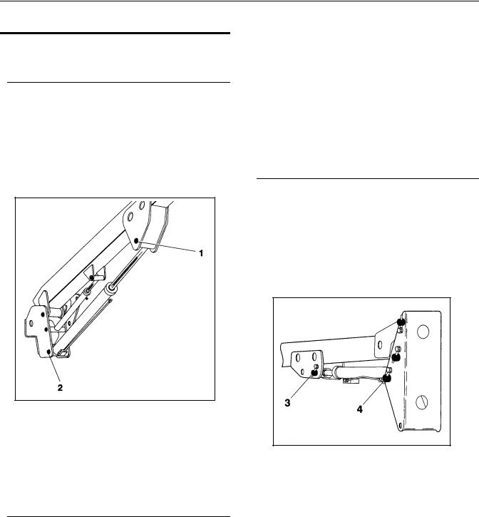
SECTION 2 - PROCEDURES
2.8CYLINDER REMOVAL AND INSTALLATION
Upper (Main) Boom Lift Cylinder Removal
1.Place the machine on a flat and level surface. Place the Upper Boom in a horizontal position. Place Lower and Mid Booms 5 degree above horizontal. Shut down machine and prop boom.
2.Tag, disconnect and cap the upper boom lift cylinder hydraulic lines and ports.
3.Remove the hardware securing the cylinder rod attach pin #1 to the boom. Using a suitable brass drift, drive out the cylinder rod attach pin #1.
Figure 2-16. Upper Boom Lift Cylinder Removal
4.Secure the cylinder with suitable slings or supports as required. Remove the hardware securing the barrel end attach pin #2. Using a suitable brass drift, drive out the barrel end attach pin #2.
5.Remove the cylinder from the boom and place in a suitable work area.
Upper (Main) Boom Lift Cylinder Installation
3.Remove cylinder port plugs and hydraulic line caps and correctly attach lines to cylinder ports.
4.With function speed switch at its slowest setting, extend the cylinder rod until attach pin hole aligns with those in boom. Using a suitable drift, drive the cylinder rod attach pin #1 through the aligned holes. Secure the pin in place with pin retaining hardware.
5.Cycle cylinder completely to check for proper functioning. Place boom in stowed position. Check hydraulic fluid level and adjust accordingly.
Mid Boom Lift Cylinder Removal
1.Place machine on flat and level surface. Place the Upper Boom in a horizontal position. Place the Mid Boom in a 10 degree elevated position. Support Upper Boom with a prop. Support upright with an overhead crane.
2.Using slings, restrain the lower lift cylinder.
3.Remove the hardware securing the cylinder rod attach pin #3 to the boom. Using an appropriate brass drift, drive out the cylinder rod attach pin #3.
Figure 2-17. Mid Boom Lift Cylinder Removal
4.Tag, disconnect and cap the lift cylinder hydraulic lines and ports.
5.Remove the hardware securing the barrel end attach pin #4 to the boom. Using an appropriate brass drift, drive out the cylinder barrel pin #4.
NOTE: Coat I.D. of bushings with specified lubricant prior to installing pins.
1.Install Lift Cylinder in place using suitable slings or supports, aligning attach pin mounting holes on upright.
2.Using a suitable drift, drive the barrel end attach pin #2 through the mounting holes in the lift cylinder and upright. Secure in place with pin retaining hardware.
6.Carefully remove cylinder from boom. Place in a suitable work area.
2-14 |
– JLG Lift – |
3120884 |
 Loading...