


Service and Maintenance Manual
Models 100SX 110SX 110SXJ 120SXJ
P/N - 3121810
July 29, 2004
INTRODUCTION
SECTION A. INTRODUCTION - MAINTENANCE SAFETY
PRECAUTIONS
A GENERAL
This section contains the general safety precautions which must be observed during maintenance of the aerial platform. It is of utmost importance that maintenance personnel pay strict attention to these warnings and precautions to avoid possible injury to themselves or others, or damage to the equipment. A maintenance program must be followed to ensure that the machine is safe to operate.
MODIFICATION OF THE MACHINE WITHOUT CERTIFICATION BY A RESPONSIBLE AUTHORITY THAT THE MACHINE IS AT LEAST
AS SAFE AS ORIGINALLY MANUFACTURED, IS A SAFETY VIOLA-
TION.
The specific precautions to be observed during maintenance are inserted at the appropriate point in the manual. These precautions are, for the most part, those that apply when servicing hydraulic and larger machine component parts.
Your safety, and that of others, is the first consideration when engaging in the maintenance of equipment. Always be conscious of weight. Never attempt to move heavy parts without the aid of a mechanical device. Do not allow heavy objects to rest in an unstable position. When raising a portion of the equipment, ensure that adequate support is provided.
SINCE THE MACHINE MANUFACTURER HAS NO DIRECT CONTROL OVER THE FIELD INSPECTION AND MAINTENANCE, SAFETY IN THIS AREA RESPONSIBILITY OF THE OWNER/OPERATOR.
feed lines to system components can then be disconnected with minimal fluid loss.
C MAINTENANCE
FAILURE TO COMPLY WITH SAFETY PRECAUTIONS LISTED IN THIS SECTION MAY RESULT IN MACHINE DAMAGE, PERSONNEL INJURY OR DEATH AND IS A SAFETY VIOLATION.
•NO SMOKING IS MANDATORY. NEVER REFUEL DURING ELECTRICAL STORMS. ENSURE THAT FUEL CAP IS CLOSED AND SECURE AT ALL OTHER TIMES.
•REMOVE ALL RINGS, WATCHES AND JEWELRY WHEN PERFORMING ANY MAINTENANCE.
•DO NOT WEAR LONG HAIR UNRESTRAINED, OR LOOSE-FITTING CLOTHING AND NECKTIES WHICH ARE APT TO BECOME CAUGHT ON OR ENTANGLED IN EQUIPMENT.
•OBSERVE AND OBEY ALL WARNINGS AND CAUTIONS ON MACHINE AND IN SERVICEMANUAL.
•KEEP OIL, GREASE, WATER, ETC. WIPED FROM STANDING SURFACES AND HAND HOLDS.
•USE CAUTION WHEN CHECKING A HOT, PRESSURIZED COOLANT SYSTEM.
•NEVER WORK UNDER AN ELEVATED BOOM UNTIL BOOM HAS BEEN SAFELY RESTRAINED FROM ANY MOVEMENT BY BLOCKING OR OVERHEAD SLING, OR BOOM SAFETY PROP HAS BEEN ENGAGED.
•BEFORE MAKING ADJUSTMENTS, LUBRICATING OR PERFORMING ANY OTHER MAINTENANCE, SHUT OFF ALL POWER CONTROLS.
•BATTERY SHOULD ALWAYS BE DISCONNECTEDDURING REPLACEMENT OF ELECTRICAL COMPONENTS.
B HYDRAULIC SYSTEM SAFETY
It should be noted that the machines hydraulic systems operate at extremely high potentially dangerous pressures. Every effort should be made to relieve any system pressure prior to disconnecting or removing any portion of the system.
Relieve system pressure by cycling the applicable control several times with the engine stopped and ignition on, to direct any line pressure back into the reservoir. Pressure
•KEEP ALL SUPPORT EQUIPMENT AND ATTACHMENTS STOWED IN THEIR PROPER PLACE.
•USE ONLY APPROVED, NONFLAMMABLE CLEANING SOLVENTS.
3121810 |
– JLG Lift – |
A-1 |

INTRODUCTION
|
REVISON LOG |
Original Issue |
- June 16, 2000 |
Revised |
- July 26, 2000 |
Revised |
- January 21, 2002 |
Revised |
- June 11, 2002 |
Revised |
- July 29, 2004 |
A-2 |
– JLG Lift – |
3121810 |

TABLE OF CONTENTS
TABLE OF CONTENTS |
|
SUBJECT - SECTION, PARAGRAPH |
PAGE NO. |
SECTION A - INTRODUCTION - MAINTENANCE SAFETY PRECAUTIONS |
|
A General . . . . . . . . . . . . . . . . . . . . . . . . . . . . . . . . . . . . . . . . . . . . . . . . . . . . . . . . . . . . . . . . . . . . . .A-1
B Hydraulic System Safety . . . . . . . . . . . . . . . . . . . . . . . . . . . . . . . . . . . . . . . . . . . . . . . . . . . . . . . . .A-1
C Maintenance . . . . . . . . . . . . . . . . . . . . . . . . . . . . . . . . . . . . . . . . . . . . . . . . . . . . . . . . . . . . . . . . . .A-1
SECTION 1 - SPECIFICATIONS
1.1 Capacities . . . . . . . . . . . . . . . . . . . . . . . . . . . . . . . . . . . . . . . . . . . . . . . . . . . . . . . . . . . . . . . . . . . .1-1 1.2 Component Data . . . . . . . . . . . . . . . . . . . . . . . . . . . . . . . . . . . . . . . . . . . . . . . . . . . . . . . . . . . . . . .1-1 Engine - Deutz F4L912 . . . . . . . . . . . . . . . . . . . . . . . . . . . . . . . . . . . . . . . . . . . . . . . . . . . . . 1-1 Torque Hub . . . . . . . . . . . . . . . . . . . . . . . . . . . . . . . . . . . . . . . . . . . . . . . . . . . . . . . . . . . . . . 1-1 Drive Motor. . . . . . . . . . . . . . . . . . . . . . . . . . . . . . . . . . . . . . . . . . . . . . . . . . . . . . . . . . . . . . . 1-1
1.3 Performance Data - 100SX, 110SX & 110SXJ . . . . . . . . . . . . . . . . . . . . . . . . . . . . . . . . . . . . . . . .1-1 Platform Height . . . . . . . . . . . . . . . . . . . . . . . . . . . . . . . . . . . . . . . . . . . . . . . . . . . . . . . . . . . 1-1 Horizontal Outreach. . . . . . . . . . . . . . . . . . . . . . . . . . . . . . . . . . . . . . . . . . . . . . . . . . . . . . . . 1-1 Below Ground Reach (110SX only). . . . . . . . . . . . . . . . . . . . . . . . . . . . . . . . . . . . . . . . . . . . 1-1 Swing . . . . . . . . . . . . . . . . . . . . . . . . . . . . . . . . . . . . . . . . . . . . . . . . . . . . . . . . . . . . . . . . . . . 1-1 Platform Capacity - Restricted (100SX & 110SX - Australia Spec Only). . . . . . . . . . . . . . . . 1-1 Platform Capacity - Unrestricted . . . . . . . . . . . . . . . . . . . . . . . . . . . . . . . . . . . . . . . . . . . . . . 1-1 Platform Rotator. . . . . . . . . . . . . . . . . . . . . . . . . . . . . . . . . . . . . . . . . . . . . . . . . . . . . . . . . . . 1-1 Jib Range of Articulation - 110SXJ . . . . . . . . . . . . . . . . . . . . . . . . . . . . . . . . . . . . . . . . . . . . 1-1 Overall Width - Axles Retracted . . . . . . . . . . . . . . . . . . . . . . . . . . . . . . . . . . . . . . . . . . . . . . . 1-1 Overall Width - Axles Extended . . . . . . . . . . . . . . . . . . . . . . . . . . . . . . . . . . . . . . . . . . . . . . . 1-1 Tailswing (Axles Extended) . . . . . . . . . . . . . . . . . . . . . . . . . . . . . . . . . . . . . . . . . . . . . . . . . . 1-1 Stowed Height . . . . . . . . . . . . . . . . . . . . . . . . . . . . . . . . . . . . . . . . . . . . . . . . . . . . . . . . . . . . 1-1 Stowed Length. . . . . . . . . . . . . . . . . . . . . . . . . . . . . . . . . . . . . . . . . . . . . . . . . . . . . . . . . . . . 1-1 Wheelbase . . . . . . . . . . . . . . . . . . . . . . . . . . . . . . . . . . . . . . . . . . . . . . . . . . . . . . . . . . . . . . . 1-2 Ground Clearance . . . . . . . . . . . . . . . . . . . . . . . . . . . . . . . . . . . . . . . . . . . . . . . . . . . . . . . . . 1-2 Gross Weight . . . . . . . . . . . . . . . . . . . . . . . . . . . . . . . . . . . . . . . . . . . . . . . . . . . . . . . . . . . . . 1-2 Max. Ground Bearing Pressure . . . . . . . . . . . . . . . . . . . . . . . . . . . . . . . . . . . . . . . . . . . . . . . 1-2 Drive Speed . . . . . . . . . . . . . . . . . . . . . . . . . . . . . . . . . . . . . . . . . . . . . . . . . . . . . . . . . . . . . . 1-2 Gradeability . . . . . . . . . . . . . . . . . . . . . . . . . . . . . . . . . . . . . . . . . . . . . . . . . . . . . . . . . . . . . . 1-2 Turning Radius (Inside) . . . . . . . . . . . . . . . . . . . . . . . . . . . . . . . . . . . . . . . . . . . . . . . . . . . . . 1-2 Turning Radius (Outside) . . . . . . . . . . . . . . . . . . . . . . . . . . . . . . . . . . . . . . . . . . . . . . . . . . . 1-2 Tire Size/Type . . . . . . . . . . . . . . . . . . . . . . . . . . . . . . . . . . . . . . . . . . . . . . . . . . . . . . . . . . . . 1-2
1.4 Performance Data - 120SXJ . . . . . . . . . . . . . . . . . . . . . . . . . . . . . . . . . . . . . . . . . . . . . . . . . . . . . .1-2 Platform Height . . . . . . . . . . . . . . . . . . . . . . . . . . . . . . . . . . . . . . . . . . . . . . . . . . . . . . . . . . . 1-2 Horizontal Outreach. . . . . . . . . . . . . . . . . . . . . . . . . . . . . . . . . . . . . . . . . . . . . . . . . . . . . . . . 1-2 Swing . . . . . . . . . . . . . . . . . . . . . . . . . . . . . . . . . . . . . . . . . . . . . . . . . . . . . . . . . . . . . . . . . . . 1-2 Platform Capacity. . . . . . . . . . . . . . . . . . . . . . . . . . . . . . . . . . . . . . . . . . . . . . . . . . . . . . . . . . 1-2 Platform Rotator. . . . . . . . . . . . . . . . . . . . . . . . . . . . . . . . . . . . . . . . . . . . . . . . . . . . . . . . . . . 1-2 Jib Range of Articulation . . . . . . . . . . . . . . . . . . . . . . . . . . . . . . . . . . . . . . . . . . . . . . . . . . . . 1-2 Overall Width - Axles Retracted . . . . . . . . . . . . . . . . . . . . . . . . . . . . . . . . . . . . . . . . . . . . . . . 1-2 Overall Width - Axles Extended . . . . . . . . . . . . . . . . . . . . . . . . . . . . . . . . . . . . . . . . . . . . . . . 1-2 Tailswing (Axles Extended) . . . . . . . . . . . . . . . . . . . . . . . . . . . . . . . . . . . . . . . . . . . . . . . . . . 1-2 Stowed Height . . . . . . . . . . . . . . . . . . . . . . . . . . . . . . . . . . . . . . . . . . . . . . . . . . . . . . . . . . . . 1-2 Stowed Length (Working) . . . . . . . . . . . . . . . . . . . . . . . . . . . . . . . . . . . . . . . . . . . . . . . . . . . 1-2 Stowed Length (Transport) . . . . . . . . . . . . . . . . . . . . . . . . . . . . . . . . . . . . . . . . . . . . . . . . . . 1-2 Wheelbase . . . . . . . . . . . . . . . . . . . . . . . . . . . . . . . . . . . . . . . . . . . . . . . . . . . . . . . . . . . . . . . 1-2 Ground Clearance . . . . . . . . . . . . . . . . . . . . . . . . . . . . . . . . . . . . . . . . . . . . . . . . . . . . . . . . . 1-2 Gross Weight . . . . . . . . . . . . . . . . . . . . . . . . . . . . . . . . . . . . . . . . . . . . . . . . . . . . . . . . . . . . . 1-2 Max. Ground Bearing Pressure . . . . . . . . . . . . . . . . . . . . . . . . . . . . . . . . . . . . . . . . . . . . . . . 1-2 Drive Speed . . . . . . . . . . . . . . . . . . . . . . . . . . . . . . . . . . . . . . . . . . . . . . . . . . . . . . . . . . . . . . 1-2 Gradeability . . . . . . . . . . . . . . . . . . . . . . . . . . . . . . . . . . . . . . . . . . . . . . . . . . . . . . . . . . . . . . 1-2 Turning Radius (Inside) . . . . . . . . . . . . . . . . . . . . . . . . . . . . . . . . . . . . . . . . . . . . . . . . . . . . . 1-2
3121810 |
– JLG Lift – |
i |

TABLE OF CONTENTS (Continued)
TABLE OF CONTENTS (continued)
SUBJECT - SECTION, PARAGRAPH |
PAGE NO. |
Turning Radius (Outside) . . . . . . . . . . . . . . . . . . . . . . . . . . . . . . . . . . . . . . . . . . . . . . . . . . . 1-2
Tire Size/Type . . . . . . . . . . . . . . . . . . . . . . . . . . . . . . . . . . . . . . . . . . . . . . . . . . . . . . . . . . . . 1-2
1.5 Torque Requirements . . . . . . . . . . . . . . . . . . . . . . . . . . . . . . . . . . . . . . . . . . . . . . . . . . . . . . . . . . .1-3
1.6 Lubrication. . . . . . . . . . . . . . . . . . . . . . . . . . . . . . . . . . . . . . . . . . . . . . . . . . . . . . . . . . . . . . . . . . . .1-3
Deutz F4L912 Engine . . . . . . . . . . . . . . . . . . . . . . . . . . . . . . . . . . . . . . . . . . . . . . . . . . . . . . 1-3
Lubrication Specifications . . . . . . . . . . . . . . . . . . . . . . . . . . . . . . . . . . . . . . . . . . . . . . . . . . . 1-4
1.7 Pressure Settings . . . . . . . . . . . . . . . . . . . . . . . . . . . . . . . . . . . . . . . . . . . . . . . . . . . . . . . . . . . . . .1-7
Main Valve . . . . . . . . . . . . . . . . . . . . . . . . . . . . . . . . . . . . . . . . . . . . . . . . . . . . . . . . . . . . . . . 1-7
1.8 Function Speeds (In Seconds) . . . . . . . . . . . . . . . . . . . . . . . . . . . . . . . . . . . . . . . . . . . . . . . . . . . .1-7
100SX. . . . . . . . . . . . . . . . . . . . . . . . . . . . . . . . . . . . . . . . . . . . . . . . . . . . . . . . . . . . . . . . . . . 1-7
110SX. . . . . . . . . . . . . . . . . . . . . . . . . . . . . . . . . . . . . . . . . . . . . . . . . . . . . . . . . . . . . . . . . . . 1-7
110SXJ. . . . . . . . . . . . . . . . . . . . . . . . . . . . . . . . . . . . . . . . . . . . . . . . . . . . . . . . . . . . . . . . . . 1-7
120SXJ. . . . . . . . . . . . . . . . . . . . . . . . . . . . . . . . . . . . . . . . . . . . . . . . . . . . . . . . . . . . . . . . . . 1-7
1.9 Cylinder Specifications . . . . . . . . . . . . . . . . . . . . . . . . . . . . . . . . . . . . . . . . . . . . . . . . . . . . . . . . . .1-8
1.10 Serial Number Locations. . . . . . . . . . . . . . . . . . . . . . . . . . . . . . . . . . . . . . . . . . . . . . . . . . . . . . . . .1-9
1.11 Critical Stability Weights . . . . . . . . . . . . . . . . . . . . . . . . . . . . . . . . . . . . . . . . . . . . . . . . . . . . . . . . .1-9
SECTION 2 - GENERAL
2.1 Machine Preparation, Inspection, and Maintenance . . . . . . . . . . . . . . . . . . . . . . . . . . . . . . . . . . .2-1
General . . . . . . . . . . . . . . . . . . . . . . . . . . . . . . . . . . . . . . . . . . . . . . . . . . . . . . . . . . . . . . . . . 2-1
Preparation, Inspection, and Maintenance . . . . . . . . . . . . . . . . . . . . . . . . . . . . . . . . . . . . . . 2-1
Pre-Start Inspection . . . . . . . . . . . . . . . . . . . . . . . . . . . . . . . . . . . . . . . . . . . . . . . . . . . . . . . . 2-1
Pre-Delivery Inspection and Frequent Inspection. . . . . . . . . . . . . . . . . . . . . . . . . . . . . . . . . 2-1
Annual Machine Inspection . . . . . . . . . . . . . . . . . . . . . . . . . . . . . . . . . . . . . . . . . . . . . . . . . . 2-1
Preventative Maintenance . . . . . . . . . . . . . . . . . . . . . . . . . . . . . . . . . . . . . . . . . . . . . . . . . . . 2-1
2.2 Service and Guidelines . . . . . . . . . . . . . . . . . . . . . . . . . . . . . . . . . . . . . . . . . . . . . . . . . . . . . . . . . .2-2
General . . . . . . . . . . . . . . . . . . . . . . . . . . . . . . . . . . . . . . . . . . . . . . . . . . . . . . . . . . . . . . . . . 2-2
Safety and Workmanship . . . . . . . . . . . . . . . . . . . . . . . . . . . . . . . . . . . . . . . . . . . . . . . . . . . 2-2
Cleanliness. . . . . . . . . . . . . . . . . . . . . . . . . . . . . . . . . . . . . . . . . . . . . . . . . . . . . . . . . . . . . . . 2-2
Components Removal and Installation . . . . . . . . . . . . . . . . . . . . . . . . . . . . . . . . . . . . . . . . . 2-3
Component Disassembly and Reassembly . . . . . . . . . . . . . . . . . . . . . . . . . . . . . . . . . . . . . 2-3
Pressure-Fit Parts . . . . . . . . . . . . . . . . . . . . . . . . . . . . . . . . . . . . . . . . . . . . . . . . . . . . . . . . . 2-3
Bearings. . . . . . . . . . . . . . . . . . . . . . . . . . . . . . . . . . . . . . . . . . . . . . . . . . . . . . . . . . . . . . . . . 2-3
Gaskets . . . . . . . . . . . . . . . . . . . . . . . . . . . . . . . . . . . . . . . . . . . . . . . . . . . . . . . . . . . . . . . . . 2-3
Bolt Usage and Torque Application . . . . . . . . . . . . . . . . . . . . . . . . . . . . . . . . . . . . . . . . . . . 2-3
Hydraulic Lines and Electrical Wiring . . . . . . . . . . . . . . . . . . . . . . . . . . . . . . . . . . . . . . . . . . 2-3
Hydraulic System. . . . . . . . . . . . . . . . . . . . . . . . . . . . . . . . . . . . . . . . . . . . . . . . . . . . . . . . . . 2-3
Lubrication . . . . . . . . . . . . . . . . . . . . . . . . . . . . . . . . . . . . . . . . . . . . . . . . . . . . . . . . . . . . . . . 2-3
Battery . . . . . . . . . . . . . . . . . . . . . . . . . . . . . . . . . . . . . . . . . . . . . . . . . . . . . . . . . . . . . . . . . . 2-3
Lubrication and Servicing . . . . . . . . . . . . . . . . . . . . . . . . . . . . . . . . . . . . . . . . . . . . . . . . . . . 2-3
2.3 Lubrication and Information . . . . . . . . . . . . . . . . . . . . . . . . . . . . . . . . . . . . . . . . . . . . . . . . . . . . . .2-4
Hydraulic System. . . . . . . . . . . . . . . . . . . . . . . . . . . . . . . . . . . . . . . . . . . . . . . . . . . . . . . . . . 2-4
Hydraulic Oil . . . . . . . . . . . . . . . . . . . . . . . . . . . . . . . . . . . . . . . . . . . . . . . . . . . . . . . . . . . . . 2-4
Changing Hydraulic Oil . . . . . . . . . . . . . . . . . . . . . . . . . . . . . . . . . . . . . . . . . . . . . . . . . . . . . 2-4
Lubrication Specifications . . . . . . . . . . . . . . . . . . . . . . . . . . . . . . . . . . . . . . . . . . . . . . . . . . . 2-4
2.4 Cylinder Drift Test . . . . . . . . . . . . . . . . . . . . . . . . . . . . . . . . . . . . . . . . . . . . . . . . . . . . . . . . . . . . . .2-5
Platform Drift . . . . . . . . . . . . . . . . . . . . . . . . . . . . . . . . . . . . . . . . . . . . . . . . . . . . . . . . . . . . . 2-5
Cylinder Drift . . . . . . . . . . . . . . . . . . . . . . . . . . . . . . . . . . . . . . . . . . . . . . . . . . . . . . . . . . . . . 2-5
2.5 Pins and Composite Bearing Repair Guidelines . . . . . . . . . . . . . . . . . . . . . . . . . . . . . . . . . . . . . .2-5
SECTION 3 - CHASSIS & TURNTABLE
3.1 Swing Bearing . . . . . . . . . . . . . . . . . . . . . . . . . . . . . . . . . . . . . . . . . . . . . . . . . . . . . . . . . . . . . . . . .3-1
Turntable Bearing Mounting Bolt Condition Check . . . . . . . . . . . . . . . . . . . . . . . . . . . . . . . 3-1
Bearing Wear Tolerance . . . . . . . . . . . . . . . . . . . . . . . . . . . . . . . . . . . . . . . . . . . . . . . . . . . . 3-1
ii |
– JLG Lift – |
3121810 |

TABLE OF CONTENTS
TABLE OF CONTENTS (continued)
SUBJECT - SECTION, PARAGRAPH |
PAGE NO. |
Bearing Replacement . . . . . . . . . . . . . . . . . . . . . . . . . . . . . . . . . . . . . . . . . . . . . . . . . . . . . . 3-3 Swing Bearing Torque Values . . . . . . . . . . . . . . . . . . . . . . . . . . . . . . . . . . . . . . . . . . . . . . . . 3-5 3.2 Swing Torque hub . . . . . . . . . . . . . . . . . . . . . . . . . . . . . . . . . . . . . . . . . . . . . . . . . . . . . . . . . . . . . .3-5 Disassembly. . . . . . . . . . . . . . . . . . . . . . . . . . . . . . . . . . . . . . . . . . . . . . . . . . . . . . . . . . . . . . 3-5 Cleaning and Inspection . . . . . . . . . . . . . . . . . . . . . . . . . . . . . . . . . . . . . . . . . . . . . . . . . . . . 3-5 Assembly . . . . . . . . . . . . . . . . . . . . . . . . . . . . . . . . . . . . . . . . . . . . . . . . . . . . . . . . . . . . . . . . 3-7
3.3 Swing Brake . . . . . . . . . . . . . . . . . . . . . . . . . . . . . . . . . . . . . . . . . . . . . . . . . . . . . . . . . . . . . . . . . .3-8 Cleaning and Inspection . . . . . . . . . . . . . . . . . . . . . . . . . . . . . . . . . . . . . . . . . . . . . . . . . . . . 3-10 Assembly . . . . . . . . . . . . . . . . . . . . . . . . . . . . . . . . . . . . . . . . . . . . . . . . . . . . . . . . . . . . . . . . 3-10
3.4 Tilt Alarm Switch Leveling . . . . . . . . . . . . . . . . . . . . . . . . . . . . . . . . . . . . . . . . . . . . . . . . . . . . . . . .3-11 Manual Adjustment . . . . . . . . . . . . . . . . . . . . . . . . . . . . . . . . . . . . . . . . . . . . . . . . . . . . . . . . 3-11 Voltmeter Adjustment . . . . . . . . . . . . . . . . . . . . . . . . . . . . . . . . . . . . . . . . . . . . . . . . . . . . . . 3-12
3.5 Load Management System . . . . . . . . . . . . . . . . . . . . . . . . . . . . . . . . . . . . . . . . . . . . . . . . . . . . . . .3-12 Platform Position Indication System . . . . . . . . . . . . . . . . . . . . . . . . . . . . . . . . . . . . . . . . . . . 3-12 Overmoment Control System . . . . . . . . . . . . . . . . . . . . . . . . . . . . . . . . . . . . . . . . . . . . . . . . 3-13 Overmoment Control Monitoring System . . . . . . . . . . . . . . . . . . . . . . . . . . . . . . . . . . . . . . . 3-14 Load Management System Daily Check . . . . . . . . . . . . . . . . . . . . . . . . . . . . . . . . . . . . . . . . 3-14
3.6 Load Management System Adjustment . . . . . . . . . . . . . . . . . . . . . . . . . . . . . . . . . . . . . . . . . . . . .3-15 3.7 Turntable Springs . . . . . . . . . . . . . . . . . . . . . . . . . . . . . . . . . . . . . . . . . . . . . . . . . . . . . . . . . . . . . .3-15 Removal . . . . . . . . . . . . . . . . . . . . . . . . . . . . . . . . . . . . . . . . . . . . . . . . . . . . . . . . . . . . . . . . . 3-15 Installation . . . . . . . . . . . . . . . . . . . . . . . . . . . . . . . . . . . . . . . . . . . . . . . . . . . . . . . . . . . . . . . 3-15
3.8 Drive and Steer Controller. . . . . . . . . . . . . . . . . . . . . . . . . . . . . . . . . . . . . . . . . . . . . . . . . . . . . . . .3-15 Controller Theory & Definitions . . . . . . . . . . . . . . . . . . . . . . . . . . . . . . . . . . . . . . . . . . . . . . . 3-15 Adjustment Procedures . . . . . . . . . . . . . . . . . . . . . . . . . . . . . . . . . . . . . . . . . . . . . . . . . . . . . 3-16
3.9 Lift and Swing Controller. . . . . . . . . . . . . . . . . . . . . . . . . . . . . . . . . . . . . . . . . . . . . . . . . . . . . . . . .3-17 Adjustment. . . . . . . . . . . . . . . . . . . . . . . . . . . . . . . . . . . . . . . . . . . . . . . . . . . . . . . . . . . . . . . 3-17 3.10 Function Control . . . . . . . . . . . . . . . . . . . . . . . . . . . . . . . . . . . . . . . . . . . . . . . . . . . . . . . . . . . . . . .3-18 Rotary Selector Controller Theory & Definitions . . . . . . . . . . . . . . . . . . . . . . . . . . . . . . . . . . 3-18 Adjustment Procedure. . . . . . . . . . . . . . . . . . . . . . . . . . . . . . . . . . . . . . . . . . . . . . . . . . . . . . 3-19
3.11 Throttle Checks and Adjustments - Deutz F4L-912 Engine . . . . . . . . . . . . . . . . . . . . . . . . . . . . . .3-19
SECTION 4 - BOOM & PLATFORM
4.1 Boom Maintenance . . . . . . . . . . . . . . . . . . . . . . . . . . . . . . . . . . . . . . . . . . . . . . . . . . . . . . . . . . . . .4-1
Removal . . . . . . . . . . . . . . . . . . . . . . . . . . . . . . . . . . . . . . . . . . . . . . . . . . . . . . . . . . . . . . . . . 4-1
Disassembly. . . . . . . . . . . . . . . . . . . . . . . . . . . . . . . . . . . . . . . . . . . . . . . . . . . . . . . . . . . . . . 4-1
Inspection . . . . . . . . . . . . . . . . . . . . . . . . . . . . . . . . . . . . . . . . . . . . . . . . . . . . . . . . . . . . . . . 4-5
Assembly . . . . . . . . . . . . . . . . . . . . . . . . . . . . . . . . . . . . . . . . . . . . . . . . . . . . . . . . . . . . . . . . 4-6
Installation . . . . . . . . . . . . . . . . . . . . . . . . . . . . . . . . . . . . . . . . . . . . . . . . . . . . . . . . . . . . . . . 4-7
4.2 Boom Chains. . . . . . . . . . . . . . . . . . . . . . . . . . . . . . . . . . . . . . . . . . . . . . . . . . . . . . . . . . . . . . . . . .4-8
Adjusting Procedures . . . . . . . . . . . . . . . . . . . . . . . . . . . . . . . . . . . . . . . . . . . . . . . . . . . . . . 4-8
Inspection Procedure . . . . . . . . . . . . . . . . . . . . . . . . . . . . . . . . . . . . . . . . . . . . . . . . . . . . . . 4-9
4.3 Wear Pads . . . . . . . . . . . . . . . . . . . . . . . . . . . . . . . . . . . . . . . . . . . . . . . . . . . . . . . . . . . . . . . . . . . .4-13
4.4 Limit Switch Adjustments . . . . . . . . . . . . . . . . . . . . . . . . . . . . . . . . . . . . . . . . . . . . . . . . . . . . . . . .4-13
Boom Limit Switch . . . . . . . . . . . . . . . . . . . . . . . . . . . . . . . . . . . . . . . . . . . . . . . . . . . . . . . . . 4-13
Horizontal Cut-Out Switch . . . . . . . . . . . . . . . . . . . . . . . . . . . . . . . . . . . . . . . . . . . . . . . . . . . 4-13
4.5 Boom Marking Tape Installation . . . . . . . . . . . . . . . . . . . . . . . . . . . . . . . . . . . . . . . . . . . . . . . . . . .4-14
4.6 BOOM LOAD RADIUS SETUP PROCEDURES - 100SX. . . . . . . . . . . . . . . . . . . . . . . . . . . . . . . . .4-15
Length Indicator Adjustment . . . . . . . . . . . . . . . . . . . . . . . . . . . . . . . . . . . . . . . . . . . . . . . . . 4-15
Boom Angle Sensor Adjustment . . . . . . . . . . . . . . . . . . . . . . . . . . . . . . . . . . . . . . . . . . . . . . 4-16
Radius Adjustment and Display Lights Setting Procedure . . . . . . . . . . . . . . . . . . . . . . . . . . 4-16
4.7 BOOM LOAD RADIUS SETUP PROCEDURES -110SXJ . . . . . . . . . . . . . . . . . . . . . . . . . . . . . . . .4-17
Length Indicator Adjustment . . . . . . . . . . . . . . . . . . . . . . . . . . . . . . . . . . . . . . . . . . . . . . . . . 4-17
Boom Angle Sensor Adjustment . . . . . . . . . . . . . . . . . . . . . . . . . . . . . . . . . . . . . . . . . . . . . . 4-17
Radius Adjustment and Display Lights Setting Procedure . . . . . . . . . . . . . . . . . . . . . . . . . . 4-18
3121810 |
– JLG Lift – |
iii |

TABLE OF CONTENTS (Continued)
TABLE OF CONTENTS (continued)
SUBJECT - SECTION, PARAGRAPH |
PAGE NO. |
4.8 BOOM LOAD RADIUS SETUP PROCEDURES - 110SX. . . . . . . . . . . . . . . . . . . . . . . . . . . . . . . . .4-19 Length Indicator Adjustment . . . . . . . . . . . . . . . . . . . . . . . . . . . . . . . . . . . . . . . . . . . . . . . . . 4-19 Boom Angle Sensor Adjustment . . . . . . . . . . . . . . . . . . . . . . . . . . . . . . . . . . . . . . . . . . . . . . 4-19 Radius Adjustment and Display Lights Setting Procedure . . . . . . . . . . . . . . . . . . . . . . . . . . 4-19
4.9 BOOM LOAD RADIUS SETUP PROCEDURES - 120SXJ . . . . . . . . . . . . . . . . . . . . . . . . . . . . . . . .4-20 Length Indicator Adjustment . . . . . . . . . . . . . . . . . . . . . . . . . . . . . . . . . . . . . . . . . . . . . . . . . 4-20 Boom Angle Sensor Adjustment . . . . . . . . . . . . . . . . . . . . . . . . . . . . . . . . . . . . . . . . . . . . . . 4-21 Radius Adjustment and Display Lights Setting Procedure . . . . . . . . . . . . . . . . . . . . . . . . . . 4-21
SECTION 5 - HYDRAULICS
5.1 |
Cylinders - Theory of Operation . . . . . . . . . . . . . . . . . . . . . . . . . . . . . . . . . . . . . . . . . . . . . . . . . . . |
5-1 |
5.2 |
Cylinder Checking Procedures . . . . . . . . . . . . . . . . . . . . . . . . . . . . . . . . . . . . . . . . . . . . . . . . . . . . |
5-1 |
|
Cylinder w/o Counterbalance Valves - Steer Cylinders, Master Level Cylinder, |
|
|
Frame Jack Cylinders |
5-1 |
|
Cylinders w/Single Counterbalance Valves - Lift Cylinder, Telescope Cylinder, |
|
|
Jib Cylinder |
5-1 |
|
Cylinders w/Dual Counterbalance Valve - Axle Extension Cylinders, |
|
|
Telescope Cylinder, Platform Slave Level Cylinder |
5-2 |
5.3 |
Cylinder Removal and Installation . . . . . . . . . . . . . . . . . . . . . . . . . . . . . . . . . . . . . . . . . . . . . . . . . |
5-2 |
|
Telescope Cylinder Removal. . . . . . . . . . . . . . . . . . . . . . . . . . . . . . . . . . . . . . . . . . . . . . . . . |
5-2 |
|
Telescope Cylinder Installation . . . . . . . . . . . . . . . . . . . . . . . . . . . . . . . . . . . . . . . . . . . . . . . |
5-3 |
|
Lift Cylinder Removal. . . . . . . . . . . . . . . . . . . . . . . . . . . . . . . . . . . . . . . . . . . . . . . . . . . . . . . |
5-4 |
|
Lift Cylinder Installation . . . . . . . . . . . . . . . . . . . . . . . . . . . . . . . . . . . . . . . . . . . . . . . . . . . . . |
5-4 |
|
Master Level Cylinder Removal . . . . . . . . . . . . . . . . . . . . . . . . . . . . . . . . . . . . . . . . . . . . . . . |
5-4 |
|
Master Level Cylinder Installation . . . . . . . . . . . . . . . . . . . . . . . . . . . . . . . . . . . . . . . . . . . . . |
5-4 |
5.4 |
Cylinder Repair . . . . . . . . . . . . . . . . . . . . . . . . . . . . . . . . . . . . . . . . . . . . . . . . . . . . . . . . . . . . . . . . |
5-5 |
|
Disassembly. . . . . . . . . . . . . . . . . . . . . . . . . . . . . . . . . . . . . . . . . . . . . . . . . . . . . . . . . . . . . . |
5-5 |
|
Cleaning and Inspection . . . . . . . . . . . . . . . . . . . . . . . . . . . . . . . . . . . . . . . . . . . . . . . . . . . . |
5-6 |
|
Assembly . . . . . . . . . . . . . . . . . . . . . . . . . . . . . . . . . . . . . . . . . . . . . . . . . . . . . . . . . . . . . . . . |
5-6 |
5.5 |
Pressure Setting Procedures . . . . . . . . . . . . . . . . . . . . . . . . . . . . . . . . . . . . . . . . . . . . . . . . . . . . . |
5-8 |
|
Main Valve . . . . . . . . . . . . . . . . . . . . . . . . . . . . . . . . . . . . . . . . . . . . . . . . . . . . . . . . . . . . . . . |
5-8 |
SECTION 6 - SCHEMATICS
6.1 General . . . . . . . . . . . . . . . . . . . . . . . . . . . . . . . . . . . . . . . . . . . . . . . . . . . . . . . . . . . . . . . . . . . . . .6-1
6.2 Troubleshooting . . . . . . . . . . . . . . . . . . . . . . . . . . . . . . . . . . . . . . . . . . . . . . . . . . . . . . . . . . . . . . .6-1
6.3 Hydraulic Circuit Checks. . . . . . . . . . . . . . . . . . . . . . . . . . . . . . . . . . . . . . . . . . . . . . . . . . . . . . . . .6-1
iv |
– JLG Lift – |
3121810 |

TABLE OF CONTENTS
LIST OF FIGURES
FIGURE NO. |
TITLE |
PAGE NO. |
1-1. Lubrication Point Location . . . . . . . . . . . . . . . . . . . . . . . . . . . . . . . . . . . . . . . . . . . . . . . . . . . . . . .1-5 1-2. Serial Number Locations. . . . . . . . . . . . . . . . . . . . . . . . . . . . . . . . . . . . . . . . . . . . . . . . . . . . . . . . .1-9 1-3. Torque Chart . . . . . . . . . . . . . . . . . . . . . . . . . . . . . . . . . . . . . . . . . . . . . . . . . . . . . . . . . . . . . . . . . .1-10 3-1. Swing Bearing Bolt Feeler Gauge Check . . . . . . . . . . . . . . . . . . . . . . . . . . . . . . . . . . . . . . . . . . . .3-1 3-2. Swing Bearing Tolerance Boom Placement . . . . . . . . . . . . . . . . . . . . . . . . . . . . . . . . . . . . . . . . . .3-2 3-3. Swing Bearing Tolerance Measuring Point. . . . . . . . . . . . . . . . . . . . . . . . . . . . . . . . . . . . . . . . . . .3-2 3-4. Swing Bearing Bolt Torquing Sequence. . . . . . . . . . . . . . . . . . . . . . . . . . . . . . . . . . . . . . . . . . . . .3-4 3-5. Swing Torque Hub . . . . . . . . . . . . . . . . . . . . . . . . . . . . . . . . . . . . . . . . . . . . . . . . . . . . . . . . . . . . .3-6 3-6. Torque Hub Carrier Timing . . . . . . . . . . . . . . . . . . . . . . . . . . . . . . . . . . . . . . . . . . . . . . . . . . . . . . .3-7 3-7. Swing Brake . . . . . . . . . . . . . . . . . . . . . . . . . . . . . . . . . . . . . . . . . . . . . . . . . . . . . . . . . . . . . . . . . .3-9 3-8. Tilt Switch Adjustment - Voltmeter . . . . . . . . . . . . . . . . . . . . . . . . . . . . . . . . . . . . . . . . . . . . . . . . .3-11 3-9. Tilt Switch Adjustment - Manual . . . . . . . . . . . . . . . . . . . . . . . . . . . . . . . . . . . . . . . . . . . . . . . . . . .3-11 3-10. Control Box Components . . . . . . . . . . . . . . . . . . . . . . . . . . . . . . . . . . . . . . . . . . . . . . . . . . . . . . . .3-13 3-11. Drive and Steer Adjustment . . . . . . . . . . . . . . . . . . . . . . . . . . . . . . . . . . . . . . . . . . . . . . . . . . . . . .3-16 3-12. Lift and Swing Adjustment . . . . . . . . . . . . . . . . . . . . . . . . . . . . . . . . . . . . . . . . . . . . . . . . . . . . . . .3-17 3-13. Function Control Card Adjustment . . . . . . . . . . . . . . . . . . . . . . . . . . . . . . . . . . . . . . . . . . . . . . . . .3-19 3-14. Throttle Checks and Adjustments - Deutz Engine . . . . . . . . . . . . . . . . . . . . . . . . . . . . . . . . . . . . .3-20 4-1. Boom Assembly - Sheet 1 of 2 . . . . . . . . . . . . . . . . . . . . . . . . . . . . . . . . . . . . . . . . . . . . . . . . . . . .4-2 4-2. Boom Assembly - Sheet 2 of 2 . . . . . . . . . . . . . . . . . . . . . . . . . . . . . . . . . . . . . . . . . . . . . . . . . . . .4-3 4-3. Typical Boom Assembly . . . . . . . . . . . . . . . . . . . . . . . . . . . . . . . . . . . . . . . . . . . . . . . . . . . . . . . . .4-9 4-4. Boom Chain Adjustments . . . . . . . . . . . . . . . . . . . . . . . . . . . . . . . . . . . . . . . . . . . . . . . . . . . . . . . .4-10 4-5. Broken Chain Limit Switch Adjustment. . . . . . . . . . . . . . . . . . . . . . . . . . . . . . . . . . . . . . . . . . . . . .4-12 4-6. Boom Marking Tape Installation - 110SXJ . . . . . . . . . . . . . . . . . . . . . . . . . . . . . . . . . . . . . . . . . . .4-14 4-7. Boom Marking Tape Installation - 100SX, 110SX, and 120SXJ . . . . . . . . . . . . . . . . . . . . . . . . . . .4-14 5-1. Cylinder Barrel Support. . . . . . . . . . . . . . . . . . . . . . . . . . . . . . . . . . . . . . . . . . . . . . . . . . . . . . . . . .5-5 5-2. Cylinder Rod Support . . . . . . . . . . . . . . . . . . . . . . . . . . . . . . . . . . . . . . . . . . . . . . . . . . . . . . . . . . .5-5 5-3. Poly-Pak Seal Installation . . . . . . . . . . . . . . . . . . . . . . . . . . . . . . . . . . . . . . . . . . . . . . . . . . . . . . . .5-6 5-4. Main Valve . . . . . . . . . . . . . . . . . . . . . . . . . . . . . . . . . . . . . . . . . . . . . . . . . . . . . . . . . . . . . . . . . . . .5-9 6-1. Electrical Components Installation - Sheet 1 . . . . . . . . . . . . . . . . . . . . . . . . . . . . . . . . . . . . . . . . .6-2 6-2. Electrical Components Installation - Sheet 2 . . . . . . . . . . . . . . . . . . . . . . . . . . . . . . . . . . . . . . . . .6-3 6-3. 100SX, 110SX Electrical Schematic - Platform - Sheet 1 of 2 . . . . . . . . . . . . . . . . . . . . . . . . . . . .6-4 6-4. 100SX, 110SX Electrical Schematic - Platform - Sheet 2 of 2 . . . . . . . . . . . . . . . . . . . . . . . . . . . .6-5 6-5. 100SX, 110SX Electrical Schematic - Boom, Turntable, Chassis - Sheet 1 of 2 . . . . . . . . . . . . . .6-6 6-6. 100SX, 110SX Electrical Schematic - Boom, Turntable, Chassis - Sheet 2 of 2 . . . . . . . . . . . . . .6-7 6-7. 110SXJ Electrical Schematic - Platform - Sheet 1 of 2 . . . . . . . . . . . . . . . . . . . . . . . . . . . . . . . . . .6-8 6-8. 110SXJ Electrical Schematic - Platform - Sheet 2 of 2 . . . . . . . . . . . . . . . . . . . . . . . . . . . . . . . . . .6-9 6-9. 110SXJ Electrical Schematic - Boom, Turntable, Chassis - Sheet 1 of 2. . . . . . . . . . . . . . . . . . . .6-10 6-10. 110SXJ Electrical Schematic - Boom, Turntable, Chassis - Sheet 2 of 2. . . . . . . . . . . . . . . . . . . .6-11 6-11. 120SXJ Electrical Schematic - Platform - Sheet 1 of 2 . . . . . . . . . . . . . . . . . . . . . . . . . . . . . . . . . .6-12 6-12. 120SXJ Electrical Schematic - Platform - Sheet 2 of 2 . . . . . . . . . . . . . . . . . . . . . . . . . . . . . . . . . .6-13 6-13. 120SXJ Electrical Schematic - Boom, Turntable, Chassis - Sheet 1 of 2. . . . . . . . . . . . . . . . . . . .6-14 6-14. 120SXJ Electrical Schematic - Boom, Turntable, Chassis - Sheet 2 of 2. . . . . . . . . . . . . . . . . . . .6-15 6-15. 100SX, 110SX, 110SXJ Hydraulic Schematic - Sheet 1 of 6 . . . . . . . . . . . . . . . . . . . . . . . . . . . . .6-16 6-16. 100SX, 110SX, 110SXJ Hydraulic Schematic - Sheet 2 of 6 . . . . . . . . . . . . . . . . . . . . . . . . . . . . .6-17 6-17. 100SX, 110SX, 110SXJ Hydraulic Schematic - Sheet 3 of 6 . . . . . . . . . . . . . . . . . . . . . . . . . . . . .6-18 6-18. 100SX, 110SX, 110SXJ Hydraulic Schematic - Sheet 4 of 6 . . . . . . . . . . . . . . . . . . . . . . . . . . . . .6-19 6-19. 100SX, 110SX, 110SXJ Hydraulic Schematic - Sheet 5 of 6 . . . . . . . . . . . . . . . . . . . . . . . . . . . . .6-20 6-20. 100SX, 110SX, 110SXJ Hydraulic Schematic - Sheet 6 of 6 . . . . . . . . . . . . . . . . . . . . . . . . . . . . .6-21 6-21. 120SXJ Hydraulic Schematic - Sheet 1 of 6 . . . . . . . . . . . . . . . . . . . . . . . . . . . . . . . . . . . . . . . . . .6-22 6-22. 120SXJ Hydraulic Schematic - Sheet 2 of 6 . . . . . . . . . . . . . . . . . . . . . . . . . . . . . . . . . . . . . . . . . .6-23 6-23. 120SXJ Hydraulic Schematic - Sheet 3 of 6 . . . . . . . . . . . . . . . . . . . . . . . . . . . . . . . . . . . . . . . . . .6-24 6-24. 120SXJ Hydraulic Schematic - Sheet 4 of 6 . . . . . . . . . . . . . . . . . . . . . . . . . . . . . . . . . . . . . . . . . .6-25 6-25. 120SXJ Hydraulic Schematic - Sheet 5 of 6 . . . . . . . . . . . . . . . . . . . . . . . . . . . . . . . . . . . . . . . . . .6-26 6-26. 120SXJ Hydraulic Schematic - Sheet 6 of 6 . . . . . . . . . . . . . . . . . . . . . . . . . . . . . . . . . . . . . . . . . .6-27
3121810 |
– JLG Lift – |
v |

TABLE OF CONTENTS (Continued)
LIST OF TABLES
TABLE NO. |
TITLE |
PAGE NO. |
1-1 Torque Requirements . . . . . . . . . . . . . . . . . . . . . . . . . . . . . . . . . . . . . . . . . . . . . . . . . . . . . . . . . . .1-3
1-2 Hydraulic Oil . . . . . . . . . . . . . . . . . . . . . . . . . . . . . . . . . . . . . . . . . . . . . . . . . . . . . . . . . . . . . . . . . .1-3
1-3 Mobil EAL Envirosyn H 46 Specs . . . . . . . . . . . . . . . . . . . . . . . . . . . . . . . . . . . . . . . . . . . . . . . . .1-4
1-4 Mobil EAL 224 H Specs . . . . . . . . . . . . . . . . . . . . . . . . . . . . . . . . . . . . . . . . . . . . . . . . . . . . . . . . .1-4
1-5 Mobil DTE 13M Specs . . . . . . . . . . . . . . . . . . . . . . . . . . . . . . . . . . . . . . . . . . . . . . . . . . . . . . . . . .1-4
1-6 Lubrication Specifications . . . . . . . . . . . . . . . . . . . . . . . . . . . . . . . . . . . . . . . . . . . . . . . . . . . . . . . .1-4
1-7 Lubrication Chart. . . . . . . . . . . . . . . . . . . . . . . . . . . . . . . . . . . . . . . . . . . . . . . . . . . . . . . . . . . . . . .1-6
1-8 Cylinder Specifications . . . . . . . . . . . . . . . . . . . . . . . . . . . . . . . . . . . . . . . . . . . . . . . . . . . . . . . . . .1-8
1-9 Critical Stability Weights . . . . . . . . . . . . . . . . . . . . . . . . . . . . . . . . . . . . . . . . . . . . . . . . . . . . . . . . .1-9
2-1 Inspection and Maintenance. . . . . . . . . . . . . . . . . . . . . . . . . . . . . . . . . . . . . . . . . . . . . . . . . . . . . .2-2
2-2 Cylinder Drift . . . . . . . . . . . . . . . . . . . . . . . . . . . . . . . . . . . . . . . . . . . . . . . . . . . . . . . . . . . . . . . . . .2-5
2-3 Inspection and Preventive Maintenance Schedule . . . . . . . . . . . . . . . . . . . . . . . . . . . . . . . . . . . .2-6
4-1 Chain Stretch Tolerance . . . . . . . . . . . . . . . . . . . . . . . . . . . . . . . . . . . . . . . . . . . . . . . . . . . . . . . . .4-12
4-2 Boom Marking Tape Installation . . . . . . . . . . . . . . . . . . . . . . . . . . . . . . . . . . . . . . . . . . . . . . . . . . .4-15
5-1 Cylinder Piston Nut Torque Specifications . . . . . . . . . . . . . . . . . . . . . . . . . . . . . . . . . . . . . . . . . . .5-7
5-2 Holding Valve Torque Specifications . . . . . . . . . . . . . . . . . . . . . . . . . . . . . . . . . . . . . . . . . . . . . . .5-8
vi |
– JLG Lift – |
3121810 |
SECTION 1 - SPECIFICATIONS
SECTION 1. SPECIFICATIONS
1.1CAPACITIES
Engine Crankcase
Deutz F4L912 w/Filter - 12.5 liters (13.2 quarts)
Fuel Tank
150 liters (40 gallons)
Hydraulic Tank
189 liters (50 gallons)
1.2COMPONENT DATA
NOTE: Tolerance on all engine rpm settings is plus or minus 10%.
Engine - Deutz F4L912
Fuel - Diesel
Oil Capacity (crankcase only) - 12 liters (12.7 quarts) Low (Mid) RPM - 1800
High RPM - 2400
Alternator - 55 Amp
Battery - 1000 cold cranking Amps, 210 minutes reserve capacity, 12 VDC
Fuel Consumption
Low RPM - 9.1 lph (2.4 gph)
High RPM - 14.2 lph (3.8 gph)
Horsepower - 70 @ 2400 RPM, no load
Torque Hub
Input Torque - 157 Nm (116 ft. lbs.)
Input Speed - 2734 rpm
Output Torque - 13878 Nm (10236 ft. lbs.)
Output Speed - 31 rpm
Static Brake Torque - 200 Nm (147.5 ft. lbs.)
Release Pressure - 18 Bar (261 psi)
Max. Release Pressure - 50 Bar (725 psi)
Drive Motor
Max. Displacement - 45 cc (2.75 in3)
Min. Displacement - 15.2 cc (0.93 in3)
Output Speed at Max. Displacement - 3000 rpm Output speed at Min. Displacement - 4000 rpm
1.3PERFORMANCE DATA - 100SX, 110SX & 110SXJ
Platform Height
100SX - 30.5 m (100ft.)
110SX & 110SXJ - 33.5 m (110 ft.)
Horizontal Outreach
16.7 m (55 ft.)
Below Ground Reach (110SX only)
3.6 m (12 ft.)
Swing
360° Continuous
Platform Capacity - Restricted (100SX &
110SX - Australia Spec Only)
450 kg (1000 lbs.)
Platform Capacity - Unrestricted
230 kg (500 lbs.)
Platform Rotator
180° Hydraulic
Jib Range of Articulation - 110SXJ
3.05 m (10 ft.) 95 degrees (+15, -80)
Overall Width - Axles Retracted
2.49 m (8 ft. 2 in.)
Overall Width - Axles Extended
3.3 m (10 ft. 10 in.)
Tailswing (Axles Extended)
86 cm (2 ft. 10 in.)
Stowed Height
3.0 m (9 ft. 10 in.)
Stowed Length
100SX - 11.55 m (37 ft. 10 in.) 110SX - 11.76 m (38 ft. 7 in.) 110SXJ - 13.46 m (44 ft. 2 in.)
3121810 |
– JLG Lift – |
1-1 |

SECTION 1 - SPECIFICATIONS
Wheelbase |
|
Jib Range of Articulation |
3.05 m (10 ft.) |
|
3.35 m (11 ft.) 95 degrees (+15, -80) |
Ground Clearance |
|
Overall Width - Axles Retracted |
|
|
|
32 cm (12.5 in.) |
|
2.49 m (8 ft. 2 in.) |
Gross Weight
100SX - 17,136 kg (37,700 lbs.) 110SX - 19,006 kg (41,900 lbs.) 110SXJ - 18,779 kg (41,400 lbs.)
Max. Ground Bearing Pressure
100SX & 110SXJ - 6.3 kg/cm2 (90 psi) 110SX - 7.0 kg/cm2 (100 psi)
Drive Speed
4.8 km/h (3 mph)
Gradeability
40%
Turning Radius (Inside)
Axles Retracted - 4.47 m (14 ft. 8 in.) Axles Extended - 3.66 m (12 ft.)
Overall Width - Axles Extended
3.3 m (10 ft. 10 in.)
Tailswing (Axles Extended)
86 cm (2 ft. 10 in.)
Stowed Height
3.05 m (10 ft.)
Stowed Length (Working)
15.95 m (52 ft. 4 in.)
Stowed Length (Transport)
10.95 m (35 ft. 11 in.)
Wheelbase
3.05 m (10 ft.)
Turning Radius (Outside)
Axles Retracted - 6.76 m (22 ft. 2 in.)
Axles Extended - 7.32 m (24 ft.)
Tire Size/Type
385/65R22.5 Foam Filled
1.4PERFORMANCE DATA - 120SXJ
Platform Height
36.58 m (120 ft.)
Horizontal Outreach
16.7 m (55 ft.)
Swing
360° Continuous
Platform Capacity
230 kg (500 lbs.)
Platform Rotator
180° Hydraulic
Ground Clearance
37 cm (14.5 in.)
Gross Weight
19,732 kg (43,500 lbs.)
Max. Ground Bearing Pressure
6.3 kg/cm2 (90 psi)
Drive Speed
4.8 km/h (3 mph)
Gradeability
40%
Turning Radius (Inside)
Axles Retracted - 3.91 m (12 ft. 10 in.) Axles Extended - 3.23 m (10 ft. 7 in.)
Turning Radius (Outside)
Axles Retracted - 5.28 m (17 ft. 4 in.) Axles Extended - 5.74 m (18 ft. 10 in.)
Tire Size/Type
445/65R22.5 Foam Filled
1-2 |
– JLG Lift – |
3121810 |

SECTION 1 - SPECIFICATIONS
1.5TORQUE REQUIREMENTS
Table 1-1.Torque Requirements
Description |
Torque Value |
Interval |
||
|
|
Hours |
||
Ft. Lbs. |
Nm |
|||
|
||||
|
|
|
|
|
Bearing to Chassis |
220 |
298 |
50/600* |
|
|
|
|
|
|
Bearing to Turntable |
220 |
298 |
50/600* |
|
|
|
|
|
|
Wheel Lugs |
180 |
245 |
100 |
|
|
|
|
|
|
Turntable Springs |
75 |
102 |
200 |
|
|
|
|
|
|
Boom Chains |
59 |
80 |
500 |
|
|
|
|
|
|
Rotator Bottom Bolt |
480 |
672 |
A/R |
|
|
|
|
|
|
* Check swing bearing bolts for security after first 50 hours of operation and every 600 hours thereafter.
NOTE: See Procedure Section for tightening sequence of turntable bearing bolts.
NOTE: When maintenance becomes necessary or a fastener has loosened, refer to the Torque Chart to determine proper torque value.
1.6 LUBRICATION
Deutz F4L912 Engine
Single Viscosity Oils (CD-SE, CD-SF)
When Outside Temp is Consistently |
Use SAE Viscosity |
|
Number |
||
|
||
|
|
|
-20° to +25° F (-29° to -4° C) |
*10W |
|
|
|
|
+15° to +50° F (-10° C to +10° C) |
20W-20 |
|
|
|
|
+40° to +85° F (+4° to +30° C) |
30 |
|
|
|
|
Above 75° F (+24° C) |
40 |
|
|
|
|
Multi-Viscosity Oils (CD-SE, CD-SF) |
|
|
|
|
|
When Outside Temp is Consistently |
Use SAE Viscosity |
|
Number |
||
|
||
|
|
|
-40° to +75° F(-40° to +24° C) |
*5W-20 |
|
|
(Synthetic) |
|
|
|
|
-5° to +70° F(-21° to +21° C) |
10W-30 |
|
|
|
|
-5° to +85° F(-21° to +30° C) |
10W-40 |
|
|
|
|
+15° to +75° F(-10° to +24° C) |
15W-30 |
|
|
|
|
Above +15° F(-10° C) |
15W-40 |
|
|
|
Table 1-2.Hydraulic Oil
Hydraulic System Operating |
SAE Viscosity |
Temperature Range |
Grade |
|
|
0° to +23° F(-18° to -5° C) |
10W |
|
|
0° to +210° F(-18° to +100° C) |
10W-20, 10W-30 |
|
|
+50° to +210° F(+10° to +99° C) |
20W-20 |
|
|
NOTE: Hydraulic oils must have anti-wear qualities at least to API Service Classification GL-3, and sufficient chemical stability for mobile hydraulic system service. JLG Industries recommends Mobilfluid 424 hydraulic oil, which has an SAE viscosity index of 152.
NOTE: When temperatures remain consistently below -7 degrees C. (20 degrees F), JLG Industries recommends the use of Mobil DTE13.
NOTE: Aside from JLG recommendations, it is not advisable to mix oils of different brands or types, as they may not contain the same required additives or be of comparable viscosities. If use of hydraulic oil other than Mobilfluid 424 is desired, contact JLG Industries for proper recommendations.
3121810 |
– JLG Lift – |
1-3 |

SECTION 1 - SPECIFICATIONS
Table 1-3. Mobil EAL Envirosyn H 46 Specs
Type |
|
Synthetic Biodegradable |
|
|
|
|
|
ISO Viscosity Grade |
|
46 |
|
|
|
|
|
Specific Gravity |
|
.910 |
|
|
|
|
|
Pour Point, Max |
|
-44°F (-44°C) |
|
|
|
|
|
Flash Point, Min. |
|
500°F (260°C) |
|
|
|
|
|
Weight |
|
7.64 lb. per gal. |
|
|
(0.9 kg per liter) |
|
|
|
|
|
|
|
|
|
|
|
Viscosity |
|
|
at 104° F (40° C) |
|
45 cSt |
|
|
|
|
|
at 212° F (100° C) |
|
8.0 cSt |
|
|
|
|
|
Viscosity Index |
|
153 |
|
|
|
|
|
Table 1-4. Mobil EAL 224 H Specs |
|
||
|
|
|
|
Type |
|
Biodegradable Vegetable Oil |
|
|
|
|
|
ISO Viscosity Grade |
|
32/46 |
|
|
|
|
|
Specific Gravity |
|
.922 |
|
|
|
|
|
Pour Point, Max |
|
-25°F (-32°C) |
|
|
|
|
|
Flash Point, Min. |
|
428°F (220°C) |
|
|
|
|
|
Weight |
|
7.64 lb. per gal. |
|
|
(0.9 kg per liter) |
|
|
|
|
|
|
|
|
|
|
|
Viscosity |
|
|
at 104° F (40° C) |
|
37 cSt |
|
|
|
|
|
at 212° F (100° C) |
|
8.4 cSt |
|
|
|
|
|
Viscosity Index |
|
213 |
|
|
|
|
|
Operating Temp |
|
0-180° F (-17 - -162°C) |
|
|
|
|
|
Note: Must be stored above 32° F (14° C)
Table 1-5. Mobil DTE 13M Specs
Type |
|
Petroleum Base |
|
|
|
ISO Viscosity Grade |
|
32 |
|
|
|
Specific Gravity |
|
.877 |
|
|
|
Pour Point, Max |
|
-40°F (-40°C) |
|
|
|
Flash Point, Min. |
|
330°F (166°C) |
|
|
|
|
Viscosity |
|
at 104° F (40° C) |
|
33 cSt |
|
|
|
at 212° F (100° C) |
|
6.5 cSt |
|
|
|
Viscosity Index |
|
140 |
|
|
|
Lubrication Specifications
|
Table 1-6.Lubrication Specifications |
|
|
KEY |
SPECIFICATIONS |
|
|
MPG |
Multipurpose Grease having a minimum dripping point of 350 |
|
degrees F. Excellent water resistance and adhesive qualities; |
|
and being of extreme pressure type (Timken OK 40 pounds |
|
minimum). |
|
|
EPGL |
Extreme Pressure Gear Lube (oil) meeting API Service Classi- |
|
fication GL-5 or Mil-Spec Mil-L-2105. |
|
|
HO |
Hydraulic Oil. API Service Classification GL-3, SAE 10W-20, |
|
Viscosity Index 152. |
|
|
EO |
Engine (crankcase) Oil. Gas - API SF/SG class, MIL-L-2104. |
|
Diesel - API CC/CD class, MIL-L-2104B/MIL-L-2104C. |
|
|
Refer to Lubrication Chart for specific lubrication procedures.
1-4 |
– JLG Lift – |
3121810 |
SECTION 1 - SPECIFICATIONS
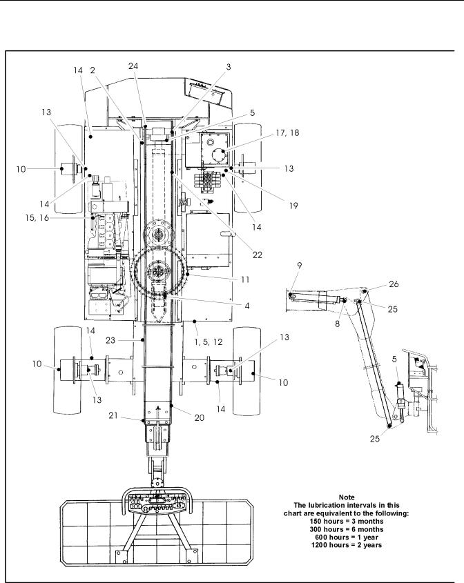
Figure 1-1. Lubrication Point Location
3121810 |
– JLG Lift – |
1-5 |

SECTION 1 - SPECIFICATIONS
Table 1-7. Lubrication Chart
|
Components |
Number/Type |
Lube & Method |
|
Interval |
Comments |
|
Lube Points |
|
Hours |
|||
|
|
|
|
|
||
|
|
|
|
|
|
|
|
|
|
|
|
|
|
1 |
Master Cylinder - Barrel End |
1 Grease Fitting |
MPG - Pressure Gun |
|
150 |
Remote Access |
|
|
|
|
|
|
|
2 |
Master Cylinder - Rod End |
1 Grease Fitting |
MPG - Pressure Gun |
|
150 |
|
|
|
|
|
|
|
|
3 |
Boom Pivot Bushings |
2 Grease Fittings |
MPG - Pressure Gun |
|
150 |
|
|
|
|
|
|
|
|
4 |
Lift Cylinder - Rod End |
1 Grease Fitting |
MPG - Pressure Gun |
|
150 |
|
|
|
|
|
|
|
|
5 |
Lift Cylinder - Barrel End |
1 Grease Fitting |
MPG - Pressure Gun |
|
150 |
Remote Access |
|
|
|
|
|
|
|
6 |
Slave Cylinder - Rod End |
1 Grease Fitting |
MPG - Pressure Gun |
|
150 |
|
|
|
|
|
|
|
|
7 |
Slave Cylinder - Barrel End |
2 Grease Fitting |
MPG - Pressure Gun |
|
150 |
|
|
|
|
|
|
|
|
8 |
Jib Cylinder - Rod End |
1 Grease Fitting |
MPGPressure Gun |
|
150 |
|
|
|
|
|
|
|
|
9 |
Jib Cylinder - Attach Pin |
2 Grease Fittings |
MPG - Pressure Gun |
|
150 |
|
|
|
|
|
|
|
|
10 |
Drive Hubs |
Fill Plug |
EPGL - SAE90 |
|
150/1200 |
Check every 150 hrs. /Change every 1200 hrs. |
|
|
|
|
|
|
|
11 |
Swing Bearing Gear |
N/A |
MPG - Brush |
|
150 |
|
|
|
|
|
|
|
|
12 |
Swing Bearing |
1 Grease Fitting |
MPG - Pressure Gun |
|
150 |
|
|
|
|
|
|
|
|
13 |
Steer Spindles |
2 Grease Fittings |
MPG - Pressure Gun |
|
150 |
|
|
|
|
|
|
|
|
14 |
Extending Axle Beams |
N/A |
MPG - Brush |
|
600 |
As needed |
|
|
|
|
|
|
|
15 |
Engine Crankcase |
Fill Cap |
EO-SAE30 |
|
10/300 |
Check daily/Change every 1000 hrs. or one |
|
|
|
|
|
|
year, whichever comes first. Adjust final level |
|
|
|
|
|
|
by mark on dipstick. |
|
|
|
|
|
|
|
16 |
Engine Oil Filter |
N/A |
Replaceable Cartridge |
|
300 |
|
|
|
|
|
|
|
|
17 |
Hydraulic Fluid |
Fill Cap |
HO |
|
10/1200 |
Check daily/Change every 1200 hrs. |
|
|
|
|
|
|
|
18 |
Hyd. Filter Element (Tank) |
N/A |
N/A |
|
50/300 |
Replace filter after first 50 hrs. of operation, |
|
|
|
|
|
|
then every 300 hrs. thereafter |
|
|
|
|
|
|
|
19 |
Hyd. Filter Element (Inline) |
N/A |
N/A |
|
50/300 |
Replace filter after first 50 hrs. of operation, |
|
|
|
|
|
|
then every 300 hrs. thereafter |
|
|
|
|
|
|
|
20 |
Telescope Cylinder Sheave |
1 Grease Fitting |
MPG - Pressure Gun |
|
150 |
|
|
|
|
|
|
|
|
21 |
Extend Chain Sheave |
1 Grease Fitting |
MPG - Pressure Gun |
|
150 |
|
|
|
|
|
|
|
|
22 |
Retract Chain Sheave |
1 Grease Fitting |
MPG - Pressure Gun |
|
150 |
|
|
|
|
|
|
|
|
23 |
Boom Chains |
N/A |
Chain Lube/Hot Oil Dip |
|
1200 |
Includes extend and retract chains |
|
|
|
|
|
|
|
24 |
Turntable Pivot Pin |
2 Grease Fittings |
MPG - Pressure Gun |
|
150 |
|
|
|
|
|
|
|
|
25 |
Jib Link Attach Pin |
1 Grease Fitting |
MPG - Pressure Gun |
|
150 |
|
|
|
|
|
|
|
|
26 |
Jib Pivot Pin |
2 Grease Fittings |
MPG - Pressure Gun |
|
150 |
|
|
|
|
|
|
|
|
NOTES: |
|
|
Key to Lubricants: |
|
||
|
|
|
|
|
|
|
|
|
|
|
EO |
|
Engine Oil |
|
|
|
|
EPGL |
Extreme Pressure Gear Lube |
|
|
|
|
|
HO |
|
Hydraulic Fluid (Mobil #424 or equivalent) |
|
|
|
|
MPG t |
Multi-Purpose Grease |
|
|
|
|
|
|
|
|
1-6 |
– JLG Lift – |
3121810 |

SECTION 1 - SPECIFICATIONS
1.7PRESSURE SETTINGS
Main Valve
Main - 238 bar (3450 psi)
Lift Down - 103 bar (1500 psi)
Jib (Up) - 207 bar (3000 psi)
Jib (Down) - 97 bar (1400 psi)
Swing - 83 bar (1200 psi)
Platform Level Up - 152 bar (2200 psi)
Platform Level Down - 172 bar (2500 psi)
Drive - 310 bar (4500 psi)
Steer - 197 bar (2850 psi)
Platform Rotate - 172 bar (2500 psi)
Extendable Axles In - 172 bar (2500 psi)
Extendable Axles Out - 172 bar (2500 psi)
NOTE: Refer to Section 2 for pressure setting procedures.
1.8FUNCTION SPEEDS (IN SECONDS)
100SX
Lift Up - 100-85
Lift Down - 100-75
Swing Right & Left - 200-140
Telescope Out - 93-74
Platform Rotate Right & Left - 20-10
Drive (61 m) - 57-47
Drive above Horizontal (15.2 m) - 89-96
110SX
Lift Up - 100-85
Lift Down - 100-75
Swing Right & Left - 200-140
Telescope Out - 100-80
Platform Rotate Right & Left - 20-10
Drive (61 m) - 57-47
Drive above Horizontal (15.2 m) - 89-96
110SXJ
Lift Up - 100-85
Lift Down - 100-75
Swing Right & Left - 200-140
Telescope Out - 93-74
Platform Rotate Right & Left - 24-36
Articulated Jib Up - 15-20
Articulated Jib Down - 45-55
Drive (61 m) - 56-46
Drive above Horizontal (15.2 m) - 89-96
120SXJ
Lift Up - 100-85
Lift Down - 100-75
Swing Right & Left - 200-140
Telescope Out - 100-80
Platform Rotate Right & Left - 24-36
Articulated Jib Up - 15-20
Articulated Jib Down - 45-55
Drive (61 m) - 56-46
Drive above Horizontal (15.2 m) - 89-96
3121810 |
– JLG Lift – |
1-7 |

SECTION 1 - SPECIFICATIONS
1.9CYLINDER SPECIFICATIONS
NOTE: All cylinder dimensions are given in inches (in), with the metric equivalent, centimeters (cm) in parentheses.
Table 1-8.Cylinder Specifications
Cylinder |
Bore |
Stroke |
Rod Dia. |
|
|
|
|
Lift |
9.0 |
43.375 |
4.0 |
|
(22.9) |
(120.3) |
(10.2) |
|
|
|
|
Master Level |
2.5 |
14.5 |
1.25 |
(100SX, 110SX) |
(6.4) |
(36.8) |
(3.2) |
|
|
|
|
Master Level |
2.5 |
15.1 |
1.25 |
(110SXJ) |
(6.4) |
(38.4) |
(3.2) |
|
|
|
|
Slave Level |
2.5 |
13.875 |
1.25 |
(100SX, 110SX) |
(6.4) |
(35.2) |
(3.2) |
|
|
|
|
Slave Level |
3.5 |
6.94 |
1.75 |
(110SXJ) |
(8.9) |
(17.6) |
(4.4) |
|
|
|
|
Steer |
3 |
10.31 |
1.5 |
|
(7.6) |
(26.2) |
(3.8) |
|
|
|
|
Telescope |
5 |
247.81 |
3.5 |
(100SX, 110SXJ |
(12.7) |
(629.4) |
(8.9) |
|
|
|
|
Telescope |
5 |
266 |
3.5 |
(110SX) |
(12.7) |
(675.6) |
(8.9) |
|
|
|
|
Axle Extension |
2.5 |
28.19 |
1.25 |
|
(6.4) |
(71.6) |
(3.2) |
|
|
|
|
Jib |
3.5 |
18.31 |
2.5 |
(110SXJ) |
(8.9 |
(46.5) |
(6.4) |
|
|
|
|
1-8 |
– JLG Lift – |
3121810 |
SECTION 1 - SPECIFICATIONS
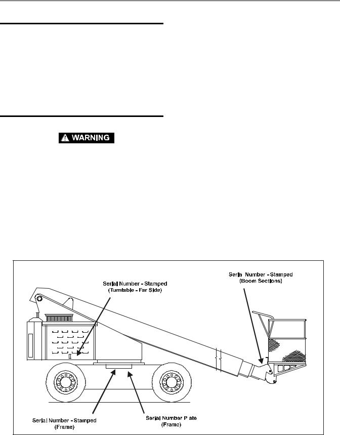
1.10 SERIAL NUMBER LOCATIONS
For machine identification, a serial number plate is affixed to the left side of the frame, below the battery compartment. If the serial number plate is damaged or missing, the machine serial number is stamped on the left side of the frame between the front and rear wheels, below the turntable bearing and on the right side of the turntable in the bottom of the valve compartment. In addition, the last five digits of the serial number are stamped on top of the fly end of the base boom section.
1.11 CRITICAL STABILITY WEIGHTS
DO NOT REPLACE ITEMS CRITICAL TO STABILITY, SUCH AS THE COUNTERWEIGHT OR FOAM-FILLED TIRES, WITH ITEMS OF DIF-
FERENT WEIGHT OR SPECIFICATION. DO NOT MODIFY UNIT IN
ANY WAY TO AFFECT STABILITY.
Table 1-9.Critical Stability Weights
Component |
100SX |
110SX |
110SXJ |
120SXJ |
|||
|
|
|
|
|
|||
Counterweight |
6150 lbs. |
10,350 lbs. |
9,850 lbs. |
9,050 lbs. |
|||
(1.5:1) |
|
(2790 kg) |
(4695 kg) |
(4468 kg) |
(4,105 kg) |
||
|
|
|
|
|
|||
Foam-Filled Tires |
700 lbs. |
700 lbs. |
700 lbs. |
932 lbs. |
|||
(each) |
(318 kg) |
(318 kg) |
(318 kg) |
(423 kg) |
|||
|
|
|
|
|
|||
Deutz Engine |
837 lbs. |
837 lbs. |
837 lbs. |
837 lbs. |
|||
|
|
|
(380 kg) |
(380 kg) |
(380 kg) |
(380 kg) |
|
|
|
|
|
|
|||
36x72 Platform |
205 lbs. |
205 lbs. |
205 lbs. |
205 lbs. |
|||
|
|
|
93 kg |
93 kg |
93 kg |
93 kg |
|
|
|
|
|
|
|||
36x96 Platform |
238 lbs. |
238 lbs. |
238 lbs. |
238 lbs. |
|||
|
|
|
(108 kg) |
(108 kg) |
(108 kg) |
(108 kg) |
|
|
|
|
|
|
|
|
|
|
|
|
|
|
|
|
|
|
|
|
|
|
|
|
|
|
|
|
|
|
|
|
|
|
|
|
|
|
|
|
|
|
|
|
|
|
|
|
|
|
|
|
|
|
|
|
|
Figure 1-2. Serial Number Locations
3121810 |
– JLG Lift – |
1-9 |

SECTION 1 - SPECIFICATIONS
UNPLATED CAP SCREWS
VALUES FOR ZINC PLATED BOLTS ONLY
UNBRAKO1960SERIES SOCKETHEADCAPSCREW |
WITHLOC-WELPATCH |
TORQUE |
(asreceived) |
NM |
CLAMPLOAD (KG) |
||||
8NUTS |
TORQUE |
(LOCTITE |
)242OR271 |
NM |
BOLTS8&GRADE |
ORY(DR |
263).LOC |
MNMN NM |
|
|
|
(LOCTITE |
262) |
|
|
|
(LUB.) |
|
|
SAEGRADE |
|
|
|
|
CLAMP |
LOAD (KG) |
|||
2NUTS |
TORQUE |
(LOCTITE |
)242OR271 |
NM |
BOLTS5&GRADE |
ORY(DR |
263).LOC |
MNMN NM |
|
|
|
(LOCTITE |
262) |
|
|
|
(LUB.) |
|
|
SAEGRADE |
|
|
|
|
CLAMP |
LOAD (KG) |
|||
THREAD |
STRESS AREA |
(SQ.CM) |
|
|
BOLT DIA. (CM) |
|
|||
|
THD |
|
|
|
|
SIZE |
|
|
|
|
|
|
|
|
1 1 |
|
2 2 |
|
245 |
272 |
1 1 |
|
1 1 |
|
172 |
191 |
0.0153 |
0.0168 |
0.2845 |
|
40 |
48 |
|
|
4 |
|
2 2 4 4 |
|||
3 3 5 5 |
|||
372 |
417 |
572 |
599 |
2 |
2 3 |
|
3 |
|
2 |
2 4 |
|
4 |
|
263 |
277 |
408 |
|
426 |
0.0232 |
0.0258 |
0.0356 |
|
0.0374 |
0.3505 |
0.4166 |
|||
32 |
40 |
32 |
|
36 |
|
|
|
|
|
6 |
8 |
|
||
5 6 |
|
7 8 |
|
717 |
817 |
4 4 |
||
5 6 |
||
508 |
|
583 |
0.0445 |
|
0.0508 |
0.4826 |
||
24 |
|
32 |
|
|
|
10 |
|
|
18 |
19 |
1442 |
1651 |
18 |
21 |
12 |
14 |
16 |
19 |
1297 |
1488 |
12 |
16 |
9 |
|
10 |
11 |
|
14 |
916 |
|
1052 |
0.0808 |
|
0.0925 |
0.6350 |
||
20 |
|
28 |
|
|
|
1/4 |
|
|
34 |
37 |
61 |
68 |
95 |
102 |
149 |
156 |
210 |
224 |
2377 |
2631 |
3493 |
3983 |
4822 |
5384 |
6437 |
7253 |
8256 |
9208 |
41 |
41 |
68 |
75 |
109 |
122 |
163 |
183 |
224 |
258 |
30 |
34 |
54 |
61 |
85 |
95 |
130 |
146 |
188 |
209 |
25 |
27 |
48 |
48 |
75 |
81 |
109 |
122 |
149 |
176 |
34 |
34 |
61 |
68 |
95 |
109 |
149 |
163 |
204 |
231 |
2141 |
2821 |
3175 |
3583 |
4332 |
4854 |
5783 |
6532 |
7539 |
8278 |
26 |
29 |
48 |
54 |
75 |
81 |
115 |
136 |
163 |
183 |
22 |
23 |
38 |
43 |
61 |
68 |
92 |
108 |
133 |
148 |
18 |
19 |
31 |
34 |
48 |
68 |
75 |
88 |
109 |
122 |
23 |
26 |
41 |
48 |
68 |
75 |
102 |
122 |
149 |
163 |
1515 |
1678 |
2241 |
2540 |
3085 |
3425 |
4105 |
4854 |
5262 |
5874 |
0.1331 |
0.1473 |
0.1969 |
0.2230 |
0.2700 |
0.3015 |
0.3604 |
0.4061 |
0.4623 |
0.5156 |
0.7938 |
0.9525 |
1.1112 |
1.2700 |
1.4288 |
|||||
18 |
24 |
16 |
24 |
14 |
20 |
13 |
20 |
12 |
18 |
|
|
|
|
|
|
|
|
|
|
5/16 |
3/8 |
7/16 |
1/2 |
9/16 |
|||||
285 |
298 |
10251 |
11612 |
326 |
359 |
244 |
277 |
231 |
244 |
298 |
326 |
9231 |
10433 |
224 |
258 |
183 |
207 |
149 |
176 |
204 |
231 |
6532 |
7394 |
0.5740 |
0.6502 |
1.5875 |
|
11 |
18 |
|
|
5/8 |
|
495 |
542 |
793 |
861 |
15150 |
16919 |
20956 |
23088 |
570 |
631 |
895 |
983 |
408 |
456 |
658 |
724 |
380 |
434 |
624 |
678 |
515 |
570 |
814 |
895 |
13653 |
15241 |
18870 |
20775 |
387 |
448 |
644 |
705 |
325 |
363 |
523 |
576 |
271 |
298 |
434 |
475 |
353 |
407 |
583 |
637 |
9662 |
10796 |
13336 |
14697 |
0.8484 |
0.9474 |
1.1735 |
1.2929 |
1.9050 |
2.2225 |
||
10 |
16 |
9 |
14 |
|
|
|
|
3/4 |
7/8 |
||
1173 |
1241 |
27488 |
30074 |
1342 |
1492 |
931 |
1079 |
922 |
1003 |
1220 |
1356 |
23360 |
27080 |
915 |
997 |
785 |
858 |
651 |
719 |
868 |
949 |
17509 |
19142 |
1.5392 |
1.6840 |
2.5400 |
|
8 |
|
12 |
|
|
|
1 |
|
1681 |
1871 |
2373 |
2549 |
3145 |
3308 |
4122 |
4433 |
34610 |
38828 |
43954 |
48671 |
52391 |
59648 |
63731 |
71669 |
1898 |
2136 |
2712 |
2983 |
3559 |
4068 |
4712 |
5322 |
1396 |
1566 |
1970 |
2183 |
2586 |
2935 |
3430 |
3856 |
1302 |
1464 |
1844 |
2034 |
2413 |
2766 |
3200 |
3607 |
1736 |
1953 |
2468 |
2712 |
3227 |
3688 |
4284 |
4827 |
31162 |
34927 |
38554 |
43818 |
47174 |
53570 |
57380 |
142200 |
1139 |
1254 |
1593 |
1762 |
2068 |
2373 |
2746 |
3118 |
968 |
1087 |
1368 |
1516 |
1792 |
2042 |
2379 |
2676 |
814 |
895 |
1139 |
1247 |
1492 |
1708 |
1980 |
2224 |
1085 |
1193 |
1519 |
1681 |
1980 |
2278 |
2630 |
2983 |
19187 |
21546 |
24404 |
27035 |
29076 |
33113 |
35381 |
39781 |
1.9380 |
2.1742 |
2.4613 |
2.7254 |
2.9337 |
3.3401 |
3.5687 |
4.0132 |
2.8575 |
3.1750 |
3.4925 |
3.8100 |
||||
7 |
12 |
7 |
12 |
6 |
12 |
6 |
12 |
|
|
|
|
|
|
|
|
1-1/8 |
1-1/4 |
1-1/2 |
1-1/2 |
||||
Note: These torque values do not apply to cadium plated fasteners.
SAE GRADE 5 SAE GRADE 8
Figure 1-3. Torque Chart
1-10 |
– JLG Lift – |
3121810 |
SECTION 2 - GENERAL
SECTION 2. GENERAL
2.1MACHINE PREPARATION, INSPECTION, AND MAINTENANCE
General
This section provides the necessary information needed by those personnel that are responsible to place the machine in operation readiness and maintain its safe operating condition. For maximum service life and safe operation, ensure that all the necessary inspections and maintenance have been completed before placing the machine into service.
Preparation, Inspection, and Maintenance
It is important to establish and conform to a comprehensive inspection and preventive maintenance program. The following table outlines the periodic machine inspections and maintenance recommended by JLG Industries, Inc. Consult your national, regional, or local regulations for further requirements for aerial work platforms. The frequency of inspections and maintenance must be increased as environment, severity and frequency of usage requires.
Pre-Start Inspection
It is the User’s or Operator’s primary responsibility to perform a Pre-Start Inspection of the machine prior to use daily or at each change of operator. Reference the Operator’s and Safety Manual for completion procedures for the Pre-Start Inspection. The Operator and Safety Manual must be read in its entirety and understood prior to performing the Pre-Start Inspection.
Pre-Delivery Inspection and Frequent
Inspection
The Pre-Delivery Inspection and Frequent Inspection shall be performed by a qualified JLG equipment mechanic. JLG Industries, Inc. recognizes a qualified JLG equipment mechanic as a person who, by possession of a recognized degree, certificate, extensive knowledge, training, or experience, has successfully demonstrated the ability and proficiency to service, repair, and maintain the subject JLG product model.
The Pre-Delivery Inspection and Frequent Inspection procedures are performed in the same manner, but at different times. The Pre-Delivery Inspection shall be performed prior to each sale, lease, or rental delivery. The Frequent Inspection shall be accomplished for each machine in service for 3 months or 150 hours (whichever comes first); out of service for a period of more than 3 months; or when purchased used. The frequency of this inspection must be increased as environment, severity and frequency of usage requires.
Reference the JLG Pre-Delivery and Frequent Inspection Form and the Inspection and Preventative Maintenance Schedule for items requiring inspection during the performance of these inspections. Reference the appropriate areas of this manual for servicing and maintenance procedures.
Annual Machine Inspection
The Annual Machine Inspection must be performed by a Factory-Certified Service Technician on an annual basis, no later than thirteen (13) months from the date of the prior Annual Machine Inspection. JLG Industries, Inc. recognizes a Factory-Certified Service Technician as a person who has successfully completed the JLG Service Training School for the subject JLG product model. Reference the machine Service and Maintenance Manual and appropriate JLG inspection form for performance of this inspection.
Reference the JLG Annual Machine Inspection Form and the Inspection and Preventative Maintenance Schedule for items requiring inspection during the performance of this inspection. Reference the appropriate areas of this manual for servicing and maintenance procedures.
For the purpose of receiving safety-related bulletins, it is important that JLG Industries, Inc. has updated ownership information for each machine. When performing each Annual Machine Inspection, notify JLG Industries, Inc. of the current machine ownership.
Preventative Maintenance
In conjunction with the specified inspections, maintenance shall be performed by a qualified JLG equipment mechanic. JLG Industries, Inc. recognizes a qualified JLG equipment mechanic as a person who, by possession of a recognized degree, certificate, extensive knowledge, training, or experience, has successfully demonstrated the ability and proficiency to service, repair, and maintain the subject JLG product model.
Reference the Preventative Maintenance Schedule and the appropriate areas of this manual for servicing and maintenance procedures. The frequency of service and maintenance must be increased as environment, severity and frequency of usage requires.
3121810 |
– JLG Lift – |
2-1 |

SECTION 2 - GENERAL
Table 2-1. Inspection and Maintenance
Type |
Frequency |
Primary |
Service |
Reference |
|
Responsibility |
Qualification |
||||
|
|
|
|||
|
|
|
|
|
|
Pre-Start Inspec- |
Prior to use each day; or |
User or Operator |
User or Operator |
Operator and Safety Manual |
|
tion |
At each Operator change. |
|
|
|
|
|
|
|
|
|
|
Pre-Delivery |
Prior to each sale, lease, or |
Owner, Dealer, or User |
Qualified JLG |
Service and Maintenance |
|
Inspection |
rental delivery. |
|
Mechanic |
Manual and applicable JLG |
|
|
|
|
|
inspection form. |
|
|
|
|
|
|
|
Frequent Inspec- |
In service for 3 months or 150 hours, which- |
Owner, Dealer, or User |
Qualified JLG |
Service and Maintenance |
|
tion |
ever comes first; or |
|
Mechanic |
Manual and applicable JLG |
|
|
Out of service for a period of more than 3 |
|
|
inspection form. |
|
|
months; or |
|
|
|
|
|
Purchased used. |
|
|
|
|
|
|
|
|
|
|
Annual Machine |
Annually, no later than 13 months from the |
Owner, Dealer, or User |
Factory-Certified |
Service and Maintenance |
|
Inspection |
date of the prior inspection. |
|
Service Technician |
Manual and applicable JLG |
|
|
|
|
|
inspection form. |
|
|
|
|
|
|
|
Preventative |
At intervals as specified in the Service and |
Owner, Dealer, or User |
Qualified JLG |
Service and Maintenance |
|
Maintenance |
Maintenance Manual. |
|
Mechanic |
Manual |
|
|
|
|
|
|
2.2SERVICE AND GUIDELINES
General
The following information is provided to assist you in the use and application of servicing and maintenance procedures contained in this book.
Safety and Workmanship
Your safety, and that of others, is the first consideration when engaging in the maintenance of equipment. Always be conscious of weight. Never attempt to move heavy parts without the aid of a mechanical device. Do not allow heavy objects to rest in an unstable position. When raising a portion of the equipment, ensure that adequate support is provided.
MAKE SURE THAT PERSONNEL ARE CLEAR OF CHASSIS AT ALL TIMES WHEN JACKS ARE EXTENDED.
JACKS RETRACT AUTOMATICALLY, LOWERING THE CHASSIS.
THE JACKS ARE TO BE USED FOR EXTENDING AND RETRACTING THE AXLES. THEY ARE NOT TO BE USED AS A MAINTE-
NANCE TOOL.
The jacks (if equipped) provided for extending and retracting the axles are not to be used as a maintenance tool. When performing maintenance on the machine which requires lifting, use adequate hydraulic jacks for lifting the machine, not the axle jacks.
Cleanliness
1.The most important single item in preserving the long service life of a machine is to keep dirt and foreign materials out of the vital components. Precautions have been taken to safeguard against this. Shields, covers, seals, and filters are provided to keep air, fuel, and oil supplies clean; however, these items must be maintained on a scheduled basis in order to function properly.
2.At any time when air, fuel, or oil lines are disconnected, clear adjacent areas as well as the openings and fittings themselves. As soon as a line or component is disconnected, cap or cover all openings to prevent entry of foreign matter.
3.Clean and inspect all parts during servicing or maintenance, and assure that all passages and openings are unobstructed. Cover all parts to keep them clean. Be sure all parts are clean before they are installed. New parts should remain in their containers until they are ready to be used.
2-2 |
– JLG Lift – |
3121810 |

SECTION 2 - GENERAL
Components Removal and Installation
1.Use adjustable lifting devices, whenever possible, if mechanical assistance is required. All slings (chains, cables, etc.) should be parallel to each other and as near perpendicular as possible to top of part being lifted.
2.Should it be necessary to remove a component on an angle, keep in mind that the capacity of an eyebolt or similar bracket lessens, as the angle between the supporting structure and the component becomes less than 90 degrees.
3.If a part resists removal, check to see whether all nuts, bolts, cables, brackets, wiring, etc., have been removed and that no adjacent parts are interfering.
Component Disassembly and Reassembly
When disassembling or reassembling a component, complete the procedural steps in sequence. Do not partially disassemble or assemble one part, then start on another. Always recheck your work to assure that nothing has been overlooked. Do not make any adjustments, other than those recommended, without obtaining proper approval.
Pressure-Fit Parts
When assembling pressure-fit parts, use an anti-seize or molybdenum disulfide base compound to lubricate the mating surface.
Bearings
1.When a bearing is removed, cover it to keep out dirt and abrasives. Clean bearings in nonflammable cleaning solvent and allow to drip dry. Compressed air can be used but do not spin the bearing.
2.Discard bearings if the races and balls (or rollers) are pitted, scored, or burned.
3.If bearing is found to be serviceable, apply a light coat of oil and wrap it in clean (waxed) paper. Do not unwrap reusable or new bearings until they are ready to install.
4.Lubricate new or used serviceable bearings before installation. When pressing a bearing into a retainer or bore, apply pressure to the outer race. If the bearing is to be installed on a shaft, apply pressure to the inner race.
Gaskets
Check that holes in gaskets align with openings in the mating parts. If it becomes necessary to hand-fabricate a gasket, use gasket material or stock of equivalent material and thickness. Be sure to cut holes in the right location, as blank gaskets can cause serious system damage.
Bolt Usage and Torque Application
1.Use bolts of proper length. A bolt which is too long will bottom before the head is tight against its related part. If a bolt is too short, there will not be enough thread area to engage and hold the part properly. When replacing bolts, use only those having the same specifications of the original, or one which is equivalent.
2.Unless specific torque requirements are given within the text, standard torque values should be used on heat-treated bolts, studs, and steel nuts, in accordance with recommended shop practices. (See Torque Chart Section 1.)
Hydraulic Lines and Electrical Wiring
Clearly mark or tag hydraulic lines and electrical wiring, as well as their receptacles, when disconnecting or removing them from the unit. This will assure that they are correctly reinstalled.
Hydraulic System
1.Keep the system clean. If evidence of metal or rubber particles are found in the hydraulic system, drain and flush the entire system.
2.Disassemble and reassemble parts on clean work surface. Clean all metal parts with non-flammable cleaning solvent. Lubricate components, as required, to aid assembly.
Lubrication
Service applicable components with the amount, type, and grade of lubricant recommended in this manual, at the specified intervals. When recommended lubricants are not available, consult your local supplier for an equivalent that meets or exceeds the specifications listed.
Battery
Clean battery, using a non-metallic brush and a solution of baking soda and water. Rinse with clean water. After cleaning, thoroughly dry battery and coat terminals with an anti corrosion compound.
Lubrication and Servicing
Components and assemblies requiring lubrication and servicing are shown in the Lubrication Chart in Section 1.
3121810 |
– JLG Lift – |
2-3 |

SECTION 2 - GENERAL
2.3 LUBRICATION AND INFORMATION
Hydraulic System
1.The primary enemy of a hydraulic system is contamination. Contaminants enter the system by various means, e.g., using inadequate hydraulic oil, allowing moisture, grease, filings, sealing components, sand, etc., to enter when performing maintenance, or by permitting the pump to cavitate due to insufficient system warm-up or leaks in the pump supply (suction) lines.
2.The design and manufacturing tolerances of the component working parts are very close, therefore, even the smallest amount of dirt or foreign matter entering a system can cause wear or damage to the components and generally results in faulty operation. Every precaution must be taken to keep hydraulic oil clean, including reserve oil in storage. Hydraulic system filters should be checked, cleaned, and/or replaced as necessary, at the specified intervals required in the Lubrication Chart in Section 1. Always examine filters for evidence of metal particles.
3.Cloudy oils indicate a high moisture content which permits organic growth, resulting in oxidation or corrosion. If this condition occurs, the system must be drained, flushed, and refilled with clean oil.
4.It is not advisable to mix oils of different brands or types, as they may not contain the same required additives or be of comparable viscosities. Good grade mineral oils, with viscosities suited to the ambient temperatures in which the machine is operating, are recommended for use.
NOTE: Metal particles may appear in the oil or filters of new machines due to the wear-in of meshing components.
Hydraulic Oil
1.Refer to Section 1 for recommendations for viscosity ranges.
2.JLG recommends Mobilfluid 424 hydraulic oil, which has an SAE viscosity of 10W-30 and a viscosity index of 152.
NOTE: Start-up of hydraulic system with oil temperatures below -15 degrees F (-26 degrees C) is not recommended. If it is necessary to start the system in a sub-zero environment, it will be necessary to heat the oil with a low density, 100VAC heater to a minimum temperature of -15 degrees F (-26 degrees C).
3.The only exception to the above is to drain and fill the system with Mobil DTE 13 oil or its equivalent. This will allow start up at temperatures down to -20 degrees F (-29 degrees C). However, use of this oil will give poor performance at temperatures above 120 degrees F (49 degrees C). Systems using DTE 13 oil should not be operated at temperatures above 200 degrees F (94 degrees C) under any condition.
Changing Hydraulic Oil
1.Use of any of the recommended crankcase or hydraulic oils eliminates the need for changing the oil on a regular basis. However, filter elements must be changed after the first 50 hours of operation and every 300 hours thereafter. If it is necessary to change the oil, use only those oils meeting or exceeding the specifications appearing in this manual. If unable to obtain the same type of oil supplied with the machine, consult local supplier for assistance in selecting the proper equivalent. Avoid mixing petroleum and synthetic base oils. JLG Industries recommends changing the hydraulic oil annually.
2.Use every precaution to keep the hydraulic oil clean. If the oil must be poured from the original container into another, be sure to clean all possible contaminants from the service container. Always clean the mesh element of the filter and replace the cartridge any time the system oil is changed.
3.While the unit is shut down, a good preventive maintenance measure is to make a thorough inspection of all hydraulic components, lines, fittings, etc., as well as a functional check of each system, before placing the machine back in service.
Lubrication Specifications
Specified lubricants, as recommended by the component manufacturers, are always the best choice, however, multi-purpose greases usually have the qualities which meet a variety of single purpose grease requirements. Should any question arise, regarding the use of greases in maintenance stock, consult your local supplier for evaluation. Refer to Section 1 for an explanation of the lubricant key designations appearing in the Lubrication Chart.
2-4 |
– JLG Lift – |
3121810 |

SECTION 2 - GENERAL
2.4CYLINDER DRIFT TEST
Maximum acceptable cylinder drift is to be measured using the following methods.
Platform Drift
Measure the drift of the platform to the ground. Lower booms (if equipped) slightly elevated, upper boom fully extended with the rated load in the platform and power off. Maximum allowable drift is 2 inches (5 cm) in 10 minutes. If the machine does not pass this test, proceed with the following.
Cylinder Drift
Table 2-2. Cylinder Drift
Cylinder Bore Diameter |
Max. Acceptable Drift |
|
in 10 Minutes |
||
|
||
|
|
inches |
mm |
inches |
mm |
|
|
|
|
3 |
76.2 |
0.026 |
0.66 |
|
|
|
|
3.5 |
89 |
0.019 |
0.48 |
|
|
|
|
4 |
101.6 |
0.015 |
0.38 |
|
|
|
|
5 |
127 |
0.009 |
0.22 |
|
|
|
|
6 |
152.4 |
0.006 |
0.15 |
|
|
|
|
7 |
177.8 |
0.005 |
0.13 |
Drift is to be measured at the cylinder rod with a calibrated dial indicator. The cylinder oil must be at ambient temperature and temperature stabilized.
The cylinder must have the normal load, which is the normal platform load applied.
If the cylinder passes this test, it is acceptable.
NOTE: This information is based on 6 drops per minute cylinder leakage.
2.5PINS AND COMPOSITE BEARING REPAIR GUIDELINES
Filament wound bearings.
1.Pinned joints should be disassembled and inspected if the following occurs:
a.Excessive sloppiness in joints.
b.Noise originating from the joint during operation.
2.Filament wound bearings should be replaced if any of the following is observed:
a.Frayed or separated fibers on the liner surface.
b.Cracked or damaged liner backing.
c.Bearings that have moved or spun in their housing.
d.Debris embedded in liner surface.
3.Pins should be replaced if any of the following is observed (pin should be properly cleaned prior to inspection):
a.Detectable wear in the bearing area.
b.Flaking, pealing, scoring, or scratches on the pin surface.
c.Rusting of the pin in the bearing area.
4.Re-assembly of pinned joints using filament wound bearings.
a.Housing should be blown out to remove all dirt and debris...bearings and bearing housings must be free of all contamination.
b.Bearing / pins should be cleaned with a solvent to remove all grease and oil...filament wound bearing are a dry joint and should not be lubricated.
c.Pins should be inspected to ensure it is free of burrs, nicks, and scratches which would damage the bearing during installation and operation.
3121810 |
– JLG Lift – |
2-5 |

SECTION 2 - GENERAL
Table 2-3. Inspection and Preventive Maintenance Schedule
|
|
|
INTERVAL |
|
|
||
|
|
|
|
|
|
|
|
AREA |
Pre-Start1 |
Weekly |
Monthly |
Pre-Delivery2 |
Annual4 |
Every 2 |
|
Preventive |
Preventive |
or Frequent3 |
(Yearly) |
||||
|
Inspection |
Years |
|||||
|
Maintenance |
Maintenance |
Inspection |
Inspection |
|||
|
|
|
|||||
Boom Assembly |
9 |
|
|
|
|
|
|
|
|
|
|
|
|
|
|
Boom Weldments |
|
|
|
1,2,4 |
1,2,4 |
|
|
|
|
|
|
|
|
|
|
Hose/Cable Carrier Installations |
|
|
|
1,2,9,12 |
1,2,9,12 |
|
|
|
|
|
|
|
|
|
|
Pivot Pins and Pin Retainers |
|
|
|
1,2 |
1,2 |
|
|
|
|
|
|
|
|
|
|
Sheaves, Sheave Pins |
|
|
|
1,2 |
1,2 |
|
|
|
|
|
|
|
|
|
|
Bearings |
|
|
|
1,2 |
1,2 |
|
|
|
|
|
|
|
|
|
|
Wear Pads |
|
|
|
1,2 |
1,2 |
|
|
|
|
|
|
|
|
|
|
Covers or Shields |
|
|
|
1,2 |
1,2 |
|
|
|
|
|
|
|
|
|
|
Extend/Retract Chain or Cable Systems |
|
|
|
1,2,3 |
1,2,3 |
|
|
|
|
|
|
|
|
|
|
Platform Assembly |
9 |
|
|
|
|
|
|
|
|
|
|
|
|
|
|
Platform |
1,2 |
|
|
|
1,2 |
|
|
|
|
|
|
|
|
|
|
Railing |
1,2 |
|
|
1 |
1,2 |
|
|
|
|
|
|
|
|
|
|
Gate |
|
|
5 |
1 |
1,5 |
|
|
|
|
|
|
|
|
|
|
Floor |
1,2 |
|
|
1 |
1,2 |
|
|
|
|
|
|
|
|
|
|
Rotator |
|
9,5 |
|
|
|
|
|
|
|
|
|
|
|
|
|
Lanyard Anchorage Point |
2 |
|
|
1,2,10 |
1,2,10 |
|
|
|
|
|
|
|
|
|
|
Turntable Assembly |
9 |
|
|
|
|
|
|
|
|
|
|
|
|
|
|
Swing Bearing or Worm Gear |
|
|
|
1,2,14 |
1,2,3,13,14 |
|
|
|
|
|
|
|
|
|
|
Oil Coupling |
|
9 |
|
|
|
|
|
|
|
|
|
|
|
|
|
Swing Drive System |
|
|
|
|
|
|
|
|
|
|
|
|
|
|
|
Turntable Lock |
|
|
|
1,2,5 |
1,2,5 |
|
|
|
|
|
|
|
|
|
|
Hood, Hood Props, Hood Latches |
|
|
|
5 |
1,2,5 |
|
|
|
|
|
|
|
|
|
|
Chassis Assembly |
9 |
|
|
|
|
|
|
|
|
|
|
|
|
|
|
Tires |
1 |
16,17 |
|
16,17,18 |
16,17,18 |
|
|
|
|
|
|
|
|
|
|
Wheel Nuts/Bolts |
1 |
15 |
|
15 |
15 |
|
|
|
|
|
|
|
|
|
|
Wheel Bearings |
|
|
|
|
|
14,24 |
|
|
|
|
|
|
|
|
|
Oscillating Axle/Lockout Cylinder Systems |
|
|
|
|
5,8 |
|
|
|
|
|
|
|
|
|
|
Outrigger or Extendable Axle Systems |
|
|
|
5,8 |
5,8 |
|
|
|
|
|
|
|
|
|
|
Steer Components |
|
|
|
|
|
|
|
|
|
|
|
|
|
|
|
Drive Motors |
|
|
|
|
|
|
|
|
|
|
|
|
|
|
|
Torque Hubs |
|
|
|
11 |
11 |
|
|
|
|
|
|
|
|
|
|
Functions/Controls |
9 |
|
|
|
|
|
|
|
|
|
|
|
|
|
|
Platform Controls |
5 |
5 |
|
6 |
6 |
|
|
|
|
|
|
|
|
|
|
Ground Controls |
5 |
5 |
|
6 |
6 |
|
|
|
|
|
|
|
|
|
|
2-6 |
– JLG Lift – |
3121810 |

SECTION 2 - GENERAL
Table 2-3. Inspection and Preventive Maintenance Schedule
|
|
|
INTERVAL |
|
|
||
|
|
|
|
|
|
|
|
AREA |
Pre-Start1 |
Weekly |
Monthly |
Pre-Delivery2 |
Annual4 |
Every 2 |
|
Preventive |
Preventive |
or Frequent3 |
(Yearly) |
||||
|
Inspection |
Years |
|||||
|
Maintenance |
Maintenance |
Inspection |
Inspection |
|||
|
|
|
|||||
Function Control Locks, Guards, or Detents |
1,5 |
1,5 |
|
5 |
5 |
|
|
|
|
|
|
|
|
|
|
Footswitch |
1,5 |
|
|
5 |
5 |
|
|
|
|
|
|
|
|
|
|
Emergency Stop Switches (Ground & Platform) |
5 |
|
|
5 |
5 |
|
|
|
|
|
|
|
|
|
|
Function Limit or Cutout Switch Systems |
|
|
|
5 |
5 |
|
|
|
|
|
|
|
|
|
|
Capacity Indicator |
|
|
|
|
5 |
|
|
|
|
|
|
|
|
|
|
Drive Brakes |
|
|
|
5 |
|
|
|
|
|
|
|
|
|
|
|
Swing Brakes |
|
|
|
5 |
|
|
|
|
|
|
|
|
|
|
|
Boom Synchronization/Sequencing Systems |
|
|
|
|
5 |
|
|
|
|
|
|
|
|
|
|
Manual Descent or Auxiliary Power |
|
|
|
5 |
5 |
|
|
|
|
|
|
|
|
|
|
Power System |
9 |
|
|
|
|
|
|
|
|
|
|
|
|
|
|
Engine Idle, Throttle, and RPM |
|
|
|
3 |
3 |
|
|
|
|
|
|
|
|
|
|
Engine Fluids (Oil, Coolant, Fuel) |
11 |
9,11 |
|
11 |
11 |
|
|
|
|
|
|
|
|
|
|
Air/Fuel Filter |
|
1,7 |
|
7 |
7 |
|
|
|
|
|
|
|
|
|
|
Exhaust System |
|
|
1,9 |
9 |
9 |
|
|
|
|
|
|
|
|
|
|
Batteries |
5 |
1,9 |
|
|
19 |
|
|
|
|
|
|
|
|
|
|
Battery Fluid |
|
11 |
|
11 |
11 |
|
|
|
|
|
|
|
|
|
|
Battery Charger |
|
5 |
|
|
5 |
|
|
|
|
|
|
|
|
|
|
Fuel Reservoir, Cap, and Breather |
11,9 |
|
2 |
1,5 |
1,5 |
|
|
|
|
|
|
|
|
|
|
Hydraulic/Electric System |
9 |
|
|
|
|
|
|
|
|
|
|
|
|
|
|
Hydraulic Pumps |
|
1,9 |
|
1,2,9 |
|
|
|
|
|
|
|
|
|
|
|
Hydraulic Cylinders |
|
1,9,7 |
2 |
1,2,9 |
1,2,9 |
|
|
|
|
|
|
|
|
|
|
Cylinder Attachment Pins and Pin Retainers |
|
1,9 |
|
1,2 |
1,2 |
|
|
|
|
|
|
|
|
|
|
Hydraulic Hoses, Lines, and Fittings |
|
1,9 |
12 |
1,2,9,12 |
1,2,9,12 |
|
|
|
|
|
|
|
|
|
|
Hydraulic Reservoir, Cap, and Breather |
11 |
1,9 |
2 |
1,5 |
1,5 |
24 |
|
|
|
|
|
|
|
|
|
Hydraulic Filter |
|
1,9 |
|
7 |
7 |
|
|
|
|
|
|
|
|
|
|
Hydraulic Fluid |
11 |
|
|
7,11 |
7,11 |
|
|
|
|
|
|
|
|
|
|
Electrical Connections |
|
1 |
|
20 |
20 |
|
|
|
|
|
|
|
|
|
|
Instruments, Gauges, Switches, Lights, Horn |
|
1 |
|
|
5,23 |
|
|
|
|
|
|
|
|
|
|
General |
|
|
|
|
|
|
|
|
|
|
|
|
|
|
|
Operators and Safety Manuals in Storage Box |
21 |
|
|
21 |
21 |
|
|
|
|
|
|
|
|
|
|
ANSI and EMI Manuals/Handbooks Installed |
|
|
|
|
21 |
|
|
|
|
|
|
|
|
|
|
Capacity Decals Installed, Secure, Legible |
21 |
|
|
21 |
21 |
|
|
|
|
|
|
|
|
|
|
All Decals/Placards Installed, Secure, Legible |
21 |
|
|
21 |
21 |
|
|
|
|
|
|
|
|
|
|
Walk-Around Inspection Performed |
21 |
|
|
|
|
|
|
|
|
|
|
|
|
|
|
3121810 |
– JLG Lift – |
2-7 |

SECTION 2 - GENERAL
Table 2-3. Inspection and Preventive Maintenance Schedule
|
|
|
INTERVAL |
|
|
||
|
|
|
|
|
|
|
|
AREA |
Pre-Start1 |
Weekly |
Monthly |
Pre-Delivery2 |
Annual4 |
Every 2 |
|
Preventive |
Preventive |
or Frequent3 |
(Yearly) |
||||
|
Inspection |
Years |
|||||
|
Maintenance |
Maintenance |
Inspection |
Inspection |
|||
|
|
|
|||||
Annual Machine Inspection Due |
|
|
|
21 |
|
|
|
|
|
|
|
|
|
|
|
No Unauthorized Modifications or Additions |
|
|
|
21 |
21 |
|
|
|
|
|
|
|
|
|
|
All Relevant Safety Publications Incorporated |
|
|
|
21 |
21 |
|
|
|
|
|
|
|
|
|
|
General Structural Condition and Welds |
|
|
|
2,4 |
2,4 |
|
|
|
|
|
|
|
|
|
|
All Fasteners, Pins, Shields, and Covers |
|
|
|
1,2 |
1,2 |
|
|
|
|
|
|
|
|
|
|
Grease and Lubricate to Specifications |
|
|
|
22 |
22 |
|
|
|
|
|
|
|
|
|
|
Function Test of All Systems |
21 |
|
|
21 |
21, 22 |
|
|
|
|
|
|
|
|
|
|
Paint and Appearance |
|
|
|
7 |
7 |
|
|
|
|
|
|
|
|
|
|
Stamp Inspection Date on Frame |
|
|
|
|
22 |
|
|
|
|
|
|
|
|
|
|
Notify JLG of Machine Ownership |
|
|
|
|
22 |
|
|
|
|
|
|
|
|
|
|
Footnotes:
1Prior to use each day; or at each Operator change
2Prior to each sale, lease, or delivery
3In service for 3 months or 150 Hours; or Out of service for 3 months or more; or Purchased used
4Annually, no later than 13 months from the date of the prior inspection
Performance Codes:
1 - Check for proper and secure installation
2 - Visual inspection for damage, cracks, distortion or excessive wear 3 - Check for proper adjustment
4 - Check for cracked or broken welds
5 - Operates Properly
6 - Returns to neutral or "off" position when released 7 - Clean and free of debris
8 - Interlocks function properly
9 - Check for signs of leakage
10 - Decals installed and legible
11 - Check for proper fluid level
12 - Check for chafing and proper routing
13 - Check for proper tolerances
14 - Properly lubricated
15 - Torqued to proper specification
16 - No gouges, excessive wear, or cords showing
17 - Properly inflated and seated around rim
18 - Proper and authorized components
19 - Fully charged
20 - No loose connections, corrosion, or abrasions
21 - Verify
22 - Perform
23 - Sealed Properly
24 - Drain, Clean, Refill
2-8 |
– JLG Lift – |
3121810 |
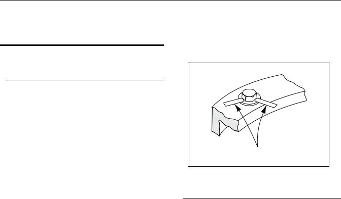
SECTION 3 - CHASSIS & TURNTABLE
SECTION 3. CHASSIS & TURNTABLE
3.1SWING BEARING
Turntable Bearing Mounting Bolt Condition
Check
NOTE: This check is designed to replace the existing bearing bolt torque checks on JLG Lifts in service. This check must be performed after the first 50 hours of machine operation and every 600 hours of machine operation thereafter. If during this check any bolts are found to be missing or loose, replace missing or loose bolts with new bolts and torque to the value specified in the torque chart, after lubricating the bolt threads with loctite #271. After replacing and retorquing bolt or bolts recheck all existing bolts for looseness.
Check the frame to bearing. Attach bolts as follows:
1.Elevate the fully retracted boom to 70 degrees (full elevation).
2.At the positions indicated on Figure 3-1., Swing Bearing Bolt Feeler Gauge Check, try and insert the 0.0015" feeler gauge between the bolt head and hardened washer at the arrow indicated position.
3.Assure that the 0.0015" feeler gauge will not penetrate under the bolt head to the bolt shank.
4.Swing the turntable 90 degrees, and check some selected bolts at the new position.
5.Continue rotating the turntable at 90 degrees intervals until a sampling of bolts have been checked in all quadrants.
Check the turntable to bearing. Attach bolts as follows:
1.Elevate the fully retracted boom to 70 degrees (full elevation).
2.At the positions indicated on Figure 3-1., Swing Bearing Bolt Feeler Gauge Check, try and insert the 0.0015" feeler gauge between the bolt head and hardened washer at the arrow indicated position.
3.Lower the boom to horizontal and fully extend the boom.
4.At the position indicated on Figure 3-1., Swing Bearing Bolt Feeler Gauge Check, try and insert the
0.0015" feeler gauge between the bolt head and hardened washer at the arrow indicated position.
.0015" Feeler Gauge
Figure 3-1. Swing Bearing Bolt Feeler Gauge Check
Bearing Wear Tolerance
1.From the underside of the machine, at rear center, with the boom fully elevated and fully retracted (Figure 3-2., Swing Bearing Tolerance Boom Placement), measure and record the distance between the swing bearing and the frame using a magnetic base dial indicator. (Figure 3-2., Swing Bearing Tolerance Boom Placement)
2.At the same point, with the boom at horizontal and extended until red marking band on mid section is exposed, measure and record the distance between the swing bearing and frame using a magnetic base dial indicator. (Figure 3-2., Swing Bearing Tolerance Boom Placement)
3.If a difference greater than 1.625 mm (0.064 in.) is determined, the swing bearing should be replaced.
4.If a difference less than 1.625 mm (0.064 in.) is determined, and any of the following conditions exist, the bearing should be removed, disassembled, and inspected for the following:
a.Metal particles in the grease.
b.Increased drive power required.
c.Noise.
d.Rough rotation.
3121810 |
– JLG Lift – |
3-1 |
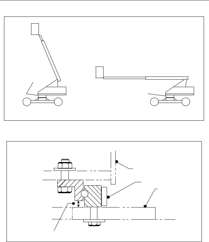
SECTION 3 - CHASSIS & TURNTABLE
 FORWARD

MEASURING POINT |
|
|
MEASURING POINT |
a. BOOM FULLY ELEVATED |
b. BOOM AT HORIZONTAL |
AND FULLY RETRACTED |
AND FULLY EXTENDED |
Figure 3-2. Swing Bearing Tolerance Boom Placement
TURNTABLE REF.
SWING BEARING
FRAME REF.
MEASURING POINT
Figure 3-3. Swing Bearing Tolerance Measuring Point
3-2 |
– JLG Lift – |
3121810 |
 Loading...