


 Loading...
Operation and Safety Manual
Original Instructions - Keep this manual with the machine at all times.
Model - 10MSP
ANSI
P/N - 3121227
®
April 9, 2013

SECTION - FOREWORD
FOREWORD
This manual is a very important tool! Keep it with the machine at all times.
The purpose of this manual is to provide owners, users, operators, lessors, and lessees with the precautions and operating procedures essential for the safe and proper machine operation for its intended purpose.
Due to continuous product improvements, JLG Industries, Inc. reserves the right to make specification changes without prior notification. Contact JLG Industries, Inc. for updated information.
Other Publications Available:
Service Manual . . . . . . . . . . . . . . . . . . . . . . . . . . .3121228
Illustrated Parts Manual . . . . . . . . . . . . . . . . . . . .3121229
3121227 |
– JLG Lift – |
a |

SECTION - SAFETY ALERT SYMBOLS AND SAFETY SIGNAL WORDS
SAFETY ALERT SYMBOLS AND SAFETY SIGNAL WORDS
This is the Safety Alert Symbol. It is used to alert you to the potential personal injury hazards. Obey all safety messages that follow this symbol to avoid possible injury or death
INDICATES AN IMMINENTLY HAZARDOUS SITUATION. IF NOT AVOIDED, WILL RESULT IN SERIOUS INJURY OR DEATH. THIS DECAL WILL HAVE A RED BACKGROUND.
INDICATES A POTENTIALITY HAZARDOUS SITUATION. IF NOT AVOIDED, COULD RESULT IN SERIOUS INJURY OR DEATH. THIS DECAL WILL HAVE AN ORANGE BACKGROUND.
INDICATES A POTENTIALITY HAZARDOUS SITUATION. IF NOT AVOIDED, MAY RESULT IN MINOR OR MODERATE INJURY. IT MAY ALSO ALERT AGAINST UNSAFE PRACTICES. THIS DECAL WILL HAVE A YELLOW BACKGROUND.
INDICATES INFORMATION OR A COMPANY POLICY THAT RELATES DIRECTLY OR INDIRECTLY TO THE SAFETY OF PERSONNEL OR PROTECTION OF PROPERTY.
b |
– JLG Lift – |
3121227 |

SECTION - SAFETY ALERT SYMBOLS AND SAFETY SIGNAL WORDS
THIS PRODUCT MUST COMPLY WITH ALL SAFETY RELATED BULLETINS. CONTACT JLG INDUSTRIES, INC. OR THE LOCAL AUTHORIZED JLG REPRESENTATIVE FOR INFORMATION REGARDING SAFETY RELATED BULLETINS WHICH MAY HAVE BEEN ISSUED FOR THIS PRODUCT.
JLG INDUSTRIES, INC. SENDS SAFETY RELATED BULLETINS TO THE OWNER OF RECORD OF THIS MACHINE. CONTACT JLG INDUSTRIES, INC. TO ENSURE THAT THE CURRENT OWNER RECORDS ARE UPDATED AND ACCURATE.
JLG INDUSTRIES, INC. MUST BE NOTIFIED IMMEDIATELY IN ALL INSTANCES WHERE JLG PRODUCTS HAVE BEEN INVOLVED IN AN ACCIDENT INVOLVING BODILY INJURY OR DEATH OF PERSONNEL OR WHEN SUBSTANTIAL DAMAGE HAS OCCURRED TO PERSONAL PROPERTY OR THE JLG PRODUCT.
For :
• Accident Reporting |
• Standards and Regulations |
|
• Product Safety Publica- |
Compliance Information |
|
|
||
tions |
• Questions Regarding Spe- |
|
• Current Owner Updates |
cial Product Applications |
|
|
||
• Questions Regarding |
• Questions Regarding Prod- |
|
uct Modifications |
||
Product Safety |
||
|
Contact :
Product Safety and Reliability Department
JLG Industries, Inc.
1 JLG Drive
McConnellsburg, PA 17233
or Your Local JLG Office
(See addresses on manual rear cover)
In USA:
Toll Free: 877-JLG-SAFE (877-554-7233)
Outside USA:
Phone: 717-485-5161
E-mail: ProductSafety@JLG.com
3121227 |
– JLG Lift – |
c |

SECTION - REVISION LOG
REVISION LOG
Original Issue of Manual . . . . . . . . . . . . . . November 14, 2005
Manual Revised . . . . . . . . . . . . . . . . . . . . . . . . October 4, 2006
Manual Revised . . . . . . . . . . . . . . . . . . . . . . . . . . . April 2, 2007
Manual Revised . . . . . . . . . . . . . . . . . . . . . .December 22, 2009
Manual Revised . . . . . . . . . . . . . . . . . . . . . . . . February 1, 2011
Manual Revised . . . . . . . . . . . . . . . . . . . . . . . February 28, 2012
Manual Revised . . . . . . . . . . . . . . . . . . . . . . . . . . . April 9, 2013
d |
– JLG Lift – |
3121227 |

TABLE OF CONTENTS
SECTION - PARAGRAPH, SUBJECT |
PAGE |
FOREWORD. . . . . . . . . . . . . . . . . . . . . . . . . . . . . . . . . . . A
SAFETY ALERT SYMBOLS AND
SAFETY SIGNAL WORDS . . . . . . . . . . . . . . . . . . . . . . . . B Contact : . . . . . . . . . . . . . . . . . . . . . . . . . . . . . . . . . . . .C In USA: . . . . . . . . . . . . . . . . . . . . . . . . . . . . . . . . . . . . .C Outside USA: . . . . . . . . . . . . . . . . . . . . . . . . . . . . . . . .C
REVISION LOG . . . . . . . . . . . . . . . . . . . . . . . . . . . . . . . .D
SECTION - 1 - SAFETY PRECAUTIONS
1.1 GENERAL. . . . . . . . . . . . . . . . . . . . . . . . . . . . . . . . . . . 1-1
1.2 PRE-OPERATION. . . . . . . . . . . . . . . . . . . . . . . . . . . . . 1-1
Operator Training And Knowledge. . . . . . . . . . . . . . 1-1
Workplace Inspection . . . . . . . . . . . . . . . . . . . . . . . . 1-2
Machine Inspection. . . . . . . . . . . . . . . . . . . . . . . . . . 1-2
1.3 OPERATION. . . . . . . . . . . . . . . . . . . . . . . . . . . . . . . . . 1-3
General . . . . . . . . . . . . . . . . . . . . . . . . . . . . . . . . . . . 1-3
Trip and Fall Hazards . . . . . . . . . . . . . . . . . . . . . . . . 1-3
Electrocution Hazards. . . . . . . . . . . . . . . . . . . . . . . . 1-4
Tipping Hazards . . . . . . . . . . . . . . . . . . . . . . . . . . . . 1-6
Crushing And Collision Hazards. . . . . . . . . . . . . . . . 1-7
1.4 LIFTING, AND HAULING . . . . . . . . . . . . . . . . . . . . . . . 1-8
General . . . . . . . . . . . . . . . . . . . . . . . . . . . . . . . . . . . 1-8
SECTION - PARAGRAPH, SUBJECT |
PAGE |
SECTION - 2 - PREPARATION AND INSPECTION
2.1 PERSONNEL TRAINING. . . . . . . . . . . . . . . . . . . . . . . . 2-1
Operator Training . . . . . . . . . . . . . . . . . . . . . . . . . . . 2-1
Training Supervision . . . . . . . . . . . . . . . . . . . . . . . . . 2-2
Operator Responsibility . . . . . . . . . . . . . . . . . . . . . . . 2-2
2.2PREPARATION, INSPECTION, AND
MAINTENANCE . . . . . . . . . . . . . . . . . . . . . . . . . . . . . . 2-2 2.3 PRE-START INSPECTION . . . . . . . . . . . . . . . . . . . . . . 2-4
2.4 DAILY WALK-AROUND INSPECTION . . . . . . . . . . . . . 2-5 Walk-Around Inspection Components . . . . . . . . . . . 2-7
2.5 FUNCTION CHECK . . . . . . . . . . . . . . . . . . . . . . . . . . . 2-8 Function Check Items:. . . . . . . . . . . . . . . . . . . . . . . . 2-8
SECTION - 3 - MACHINE OPERATION
3.1 GENERAL . . . . . . . . . . . . . . . . . . . . . . . . . . . . . . . . . . . 3-1 3.2 MACHINE DESCRIPTION. . . . . . . . . . . . . . . . . . . . . . . 3-1
3.3 MACHINE OPERATION . . . . . . . . . . . . . . . . . . . . . . . . 3-2 Getting Started. . . . . . . . . . . . . . . . . . . . . . . . . . . . . . 3-2
3.4 HOOD - (CARRY DECK). . . . . . . . . . . . . . . . . . . . . . . . 3-4 Removal: . . . . . . . . . . . . . . . . . . . . . . . . . . . . . . . . . . 3-4 Installation:. . . . . . . . . . . . . . . . . . . . . . . . . . . . . . . . . 3-4
3.5 BATTERY CHARGING . . . . . . . . . . . . . . . . . . . . . . . . . 3-5 Battery Low Voltage Warning Indicators . . . . . . . . . . 3-5
3121227 |
– JLG Lift – |
i |

TABLE OF CONTENTS
SECTION - PARAGRAPH, SUBJECT |
PAGE |
To Charge Batteries. . . . . . . . . . . . . . . . . . . . . . . . . . 3-6
Battery Charging Status Indicators . . . . . . . . . . . . . . 3-7
3.6 GROUND CONTROL STATION - OPERATION . . . . . 3-10
Platform/Off/Ground Selector Switch . . . . . . . . . . . 3-11
Emergency Stop/Shut Down Button . . . . . . . . . . . 3-11
Brake Release Button . . . . . . . . . . . . . . . . . . . . . . . 3-12
Platform Up and Down Buttons. . . . . . . . . . . . . . . . 3-12
Machine Status LCD Display. . . . . . . . . . . . . . . . . . 3-13
Tilt Alarm Warning . . . . . . . . . . . . . . . . . . . . . . . . . . 3-14
LCD Display Fault Conditions . . . . . . . . . . . . . . . . . 3-14
3.7 PLATFORM CONTROL CONSOLE-OPERATION . . . 3-17
General . . . . . . . . . . . . . . . . . . . . . . . . . . . . . . . . . . 3-18
Platform On/Off Key Switch. . . . . . . . . . . . . . . . . . . 3-18
Platform Emergency Stop/Shut Down Button . . . . 3-19
Platform Control Display Panel . . . . . . . . . . . . . . . . 3-19
Drive/Lift Mode Selector Switch . . . . . . . . . . . . . . . 3-21
Joystick Function Enable Lever . . . . . . . . . . . . . . . 3-21
Multifunction Joystick Control . . . . . . . . . . . . . . . . . 3-22
Horn Button . . . . . . . . . . . . . . . . . . . . . . . . . . . . . . . 3-23
Drive Speed Setting Controls . . . . . . . . . . . . . . . . . 3-24
3.8 PLATFORM FUNCTION ENABLE FOOT SWITCH. . . 3-25
3.9PLATFORM MANUAL DESCENT CONTROL
VALVE. . . . . . . . . . . . . . . . . . . . . . . . . . . . . . . . . . . . . 3-26
Activating the Manual Descent Valve . . . . . . . . . . . 3-26
SECTION - PARAGRAPH, SUBJECT |
PAGE |
|
3.10 |
PLATFORM CONFIGURATION. . . . . . . . . . . . . . . . |
. . 3-27 |
|
Platform Lanyard Anchorage Point . . . . . . . . . . . . |
3-27 |
|
Material Handling Tray - Height Adjustment . . . . . |
3-28 |
|
Material Handling Tray - Cargo Strap-OPTION . . . |
3-29 |
3.11 |
PARKING MACHINE . . . . . . . . . . . . . . . . . . . . . . . . . |
. 3-29 |
3.12 |
TRANSPORTING, LIFTING AND TIE-DOWN PROCE- |
|
|
DURES . . . . . . . . . . . . . . . . . . . . . . . . . . . . . . . . . . . |
. 3-30 |
|
General. . . . . . . . . . . . . . . . . . . . . . . . . . . . . . . . . . |
3-30 |
|
Fork-Lift Truck Transport . . . . . . . . . . . . . . . . . . . . |
3-30 |
|
Vehicle Transport - Tied-Down Using the |
|
|
Tie-Down Loops . . . . . . . . . . . . . . . . . . . . . . . . . . . |
3-31 |
3.13 |
PROGRAMMABLE SECURITY LOCK (PSL™) |
|
|
(OPTION). . . . . . . . . . . . . . . . . . . . . . . . . . . . . . . . . . |
. 3-32 |
|
PSL™ Box Location . . . . . . . . . . . . . . . . . . . . . . . . |
3-32 |
|
Machine - Power Up using the PSL™ . . . . . . . . . . |
3-33 |
|
Machine - Power Down . . . . . . . . . . . . . . . . . . . . . |
3-33 |
|
Changing the Operator’s Code . . . . . . . . . . . . . . . |
3-33 |
3.14 |
PLATFORM HANGER ACCESSORY - (OPTION) . . . |
. 3-34 |
|
Hanger Accessory - Pre-Start Inspection . . . . . . . |
3-35 |
|
Loading and Transporting an Item using the |
|
|
Hanger Accessory . . . . . . . . . . . . . . . . . . . . . . . . . |
3-35 |
3.15 |
RUG CARRIER ACCESSORY - (OPTION) . . . . . . . . |
. 3-35 |
|
Pre-Start Inspection . . . . . . . . . . . . . . . . . . . . . . . . |
3-35 |
|
Hanging a Rug . . . . . . . . . . . . . . . . . . . . . . . . . . . . |
3-36 |
ii |
– JLG Lift – |
3121227 |

TABLE OF CONTENTS
SECTION - PARAGRAPH, SUBJECT |
PAGE |
Removing a Rug . . . . . . . . . . . . . . . . . . . . . . . . . . . 3-38
3.16 FLOURSCENT TUBE CADDY - (OPTION). . . . . . . . . 3-40
Pre-Start Inspection . . . . . . . . . . . . . . . . . . . . . . . . 3-40
3.17 DECAL INSTALLATION . . . . . . . . . . . . . . . . . . . . . . . 3-41
SECTION - 4 - EMERGENCY PROCEDURES
4.1 GENERAL INFORMATION. . . . . . . . . . . . . . . . . . . . . . 4-1
4.2 EMERGENCY OPERATION . . . . . . . . . . . . . . . . . . . . . 4-1 Operator Unable to Control Machine . . . . . . . . . . . . 4-1 Platform Caught Overhead . . . . . . . . . . . . . . . . . . . . 4-1
4.3 INCIDENT NOTIFICATION. . . . . . . . . . . . . . . . . . . . . . 4-1
SECTION - 5 - GENERAL SPECIFICATIONS AND OPERATOR
MAINTENANCE
5.1 INTRODUCTION . . . . . . . . . . . . . . . . . . . . . . . . . . . . . 5-1
5.2 GENERAL SPECIFICATIONS . . . . . . . . . . . . . . . . . . . 5-2
Machine Specifications. . . . . . . . . . . . . . . . . . . . . . . 5-2
Electrical Specifications . . . . . . . . . . . . . . . . . . . . . . 5-3
Platform Data . . . . . . . . . . . . . . . . . . . . . . . . . . . . . . 5-3
Machine Component Weights . . . . . . . . . . . . . . . . . 5-4
Serial Number Location . . . . . . . . . . . . . . . . . . . . . . 5-4
5.3 OPERATOR MAINTENANCE . . . . . . . . . . . . . . . . . . . . 5-5
Lubrication . . . . . . . . . . . . . . . . . . . . . . . . . . . . . . . . 5-5
SECTION - PARAGRAPH, SUBJECT |
PAGE |
5.4 BATTERY MAINTENANCE . . . . . . . . . . . . . . . . . . . . . . 5-8
5.5 TIRES AND WHEELS . . . . . . . . . . . . . . . . . . . . . . . . . . 5-8 Tire Wear and Damage . . . . . . . . . . . . . . . . . . . . . . . 5-8 Wheel and Tire Replacement . . . . . . . . . . . . . . . . . . 5-8 Wheel Installation. . . . . . . . . . . . . . . . . . . . . . . . . . . . 5-8
5.6 GROUND CONTROL STATION-PROGRAMMING . . . 5-10 General . . . . . . . . . . . . . . . . . . . . . . . . . . . . . . . . . . 5-10 Programming Levels . . . . . . . . . . . . . . . . . . . . . . . . 5-10 Operator Programming Mode . . . . . . . . . . . . . . . . . 5-10 Tilt Sensor . . . . . . . . . . . . . . . . . . . . . . . . . . . . . . . . 5-10 Programming Items . . . . . . . . . . . . . . . . . . . . . . . . . 5-11 Activating Programming Mode . . . . . . . . . . . . . . . . 5-13 Entering Password . . . . . . . . . . . . . . . . . . . . . . . . . 5-14 Programming Mode Selection . . . . . . . . . . . . . . . . 5-14 Selecting Programmable Item to Adjust . . . . . . . . . 5-15 Adjusting Programmable Setting . . . . . . . . . . . . . . 5-15
5.7DRIVE MOTOR BRUSH WEAR -
WARNING INDICATION . . . . . . . . . . . . . . . . . . . . . . . 5-16 5.8 SUPPLEMENTAL INFORMATION . . . . . . . . . . . . . . . 5-17
SECTION - 6 - INSPECTION AND REPAIR LOG
3121227 |
– JLG Lift – |
iii |

TABLE OF CONTENTS
SECTION - PARAGRAPH, SUBJECT |
PAGE |
SECTION - PARAGRAPH, SUBJECT |
PAGE |
|||
|
LIST OF FIGURES |
|
|
Specification) . . . . . . . . . . . . . . . . . . . . . . . . . . . |
. . 3-42 |
|
2-1. |
Daily Walk-Around Inspection for 10MSP |
|
3-18. |
10MSP Decal Installation Chart - |
|
|
|
|
(See Table 3-4 (ANSI) and (CE) for |
|
|||
|
Machines |
2-6 |
|
|
||
|
|
Specification) |
3-43 |
|||
3-1. |
10MSP - Machine Operating Specifications |
3-2 |
|
|||
5-1. |
Wheel Lug Nut Tightening Sequence |
5-9 |
||||
3-2. |
Machine Operating Component Locations |
3-3 |
||||
|
|
|
||||
3-3. |
Carry Deck - Hood Removal. . . . . . . . . . . . . . . . |
. . 3-4 |
|
|
|
|
3-4. |
Battery Charger Location (Hood Removed - |
3-7 |
|
LIST OF TABLES |
|
|
|
For Hood Removal, See page 3-4). . . . . . . . . . . |
|
|
|
||
3-5. |
Ground Control Station. . . . . . . . . . . . . . . . . . . . |
. 3-10 |
1-1 |
Minimum Approach Distances (M.A.D.) . . . . . . . |
. 1-5 |
|
3-6. |
Platform Control Console.. . . . . . . . . . . . . . . . . . . 3-17 |
2-1 |
Inspection and Maintenance Table . . . . . . . . . . . |
. 2-3 |
||
3-7. |
Platform Control Display Panel. . . . . . . . . . . . . . |
. 3-19 |
3-1 |
Battery Low Voltage Warning Indicators. . . . . . . |
. 3-5 |
|
3-8. |
Manual Descent Valve Location . . . . . . . . . . . . . |
. 3-26 |
3-2 |
LCD Display - Operating Fault Conditions . . . . . |
3-15 |
|
3-9. |
Standard Platform (10MSP) . . . . . . . . . . . . . . . . |
. 3-27 |
3-3 |
Platform Maximum Capacity . . . . . . . . . . . . . . . . |
3-27 |
|
3-10. |
Material Handling Tray Height Adjustment. . . . . |
. 3-28 |
3-4 |
10MSP - (ANSI and CE) Decal Installation |
|
|
3-11. |
Material Handling Tray - Cargo Strap - Option. . |
. 3-29 |
|
Chart (See Figure 3-16., Figure 3-17. and |
|
|
3-12. |
Forklift Truck Lifting Pockets. . . . . . . . . . . . . . . . |
. 3-30 |
|
Figure 3-18.). . . . . . . . . . . . . . . . . . . . . . . . . . . . . |
3-44 |
|
3-13. |
Front and Rear Tie-Down Loop. . . . . . . . . . . . . . |
. 3-31 |
5-1 |
Lubrication Specifications . . . . . . . . . . . . . . . . . . |
. 5-5 |
|
3-14. |
PSL™ Switch Location . . . . . . . . . . . . . . . . . . . . |
. 3-32 |
5-2. |
Lubrication Intervals for Various Components . . |
. 5-7 |
|
3-15. |
PSL™ Switch Controls & Indicators.. . . . . . . . . . . 3-32 |
5-3 |
Wheel Torque Chart. . . . . . . . . . . . . . . . . . . . . . . |
. 5-9 |
||
3-16. |
10MSP Decal Installation Chart - |
|
5-4 |
Ground Control Station - Level 3 - |
|
|
|
(See Table 3-4 (ANSI) and (CE) for |
|
|
Programmable Settings and Factory Presets.. . . .5-12 |
||
|
Specification) . . . . . . . . . . . . . . . . . . . . . . . . . . . |
. 3-41 |
6-1 |
Inspection and Repair Log. . . . . . . . . . . . . . . . . . |
. 6-1 |
|
3-17. |
10MSP Decal Installation Chart - |
|
|
|
|
|
|
(See Table 3-4 (ANSI) and (CE) for |
|
|
|
|
|
|
|
|
|
|
|
|
iv |
– JLG Lift – |
3121227 |
SECTION 1 - SAFETY PRECAUTIONS
SECTION 1. SAFETY PRECAUTIONS
1.1GENERAL
This section outlines the necessary precautions for proper and safe machine usage and maintenance. For proper machine use, it is mandatory that a daily routine is established based on the content of this manual. A maintenance program, using the information provided in this manual and the Service and Maintenance Manual, must also be established by a qualified person and must be followed to ensure that the machine is safe to operate.
The owner/user/operator/lessor/lessee of the machine should not accept operating responsibility until this manual has been read, training is accomplished, and operation of the machine has been completed under the supervision of an experienced and qualified operator.
If there are any questions with regard to safety, training, inspection, maintenance, application, and operation, please contact JLG Industries, Inc. (“JLG”).
FAILURE TO COMPLY WITH THE SAFETY PRECAUTIONS LISTED IN THIS MANUAL COULD RESULT IN MACHINE DAMAGE, PROPERTY DAMAGE, PERSONAL INJURY OR DEATH.
THE FOLLOWING INFORMATION IS PROVIDED IN ACCORDANCE WITH THE REQUIREMENTS OF THE EUROPEAN MACHINERY DIRECTIVE 2006/42/EC AND IS ONLY APPLICABLE TO CE MACHINES:
FOR ELECTRIC POWERED MACHINES, THE EQUIVALENT CONTINUOUS A-WEIGHTED SOUND PRESSURE LEVEL AT THE WORK PLATFORM IS LESS THAN 70DB(A).
FOR COMBUSTION ENGINE POWERED MACHINES, GUARANTEED SOUND POWER LEVEL (LWA) PER EUROPEAN DIRECTIVE 2000/ 14/EC (NOISE EMISSION IN THE ENVIRONMENT BY EQUIPMENT FOR USE OUTDOORS) BASED ON TEST METHODS IN ACCORDANCE WITH ANNEX III, PART B, METHOD 1 AND 0 OF THE DIRECTIVE, IS 109 DB.
THE VIBRATION TOTAL VALUE TO WHICH THE HAND-ARM SYSTEM IS SUBJECTED DOES NOT EXCEED 2,5 M/S2. THE HIGHEST ROOT MEAN SQUARE VALUE OF WEIGHTED ACCELERATION TO WHICH THE WHOLE BODY IS SUBJECTED DOES NOT EXCEED 0,5 M/S2.
3121227 |
– JLG Lift – |
1-1 |

SECTION 1 - SAFETY PRECAUTIONS
1.2PRE-OPERATION
Operator Training And Knowledge
•Read and understand this manual before operating the machine.
•Do not operate this machine until complete training is performed by authorized persons.
•Only authorized and qualified personnel can operate the machine.
•Read, understand, and obey all DANGERS, WARNINGS, CAUTIONS, and operating instructions on the machine and in this manual.
•Use the machine in a manner which is within the scope of its intended application set by JLG.
•All operating personnel must be familiar with the emergency controls and emergency operation of the machine as specified in this manual.
•Read, understand, and obey all applicable employer, local, and governmental regulations as they pertain to operation of the machine.
Workplace Inspection
•The operator is to take safety measures to avoid all hazards in the work area prior to machine operation.
•Do not operate or raise the platform while on trucks, trailers, railway cars, floating vessels, scaffolds or other equipment unless approved in writing by JLG.
•This machine can be operated in temperatures of 0° F to 104° F (-20° C to 40° C). Consult JLG for operation outside this range.
Machine Inspection
•Before machine operation, perform inspections and functional checks. Refer to Section 2 of this manual for detailed instructions.
•Do not operate this machine until it has been serviced and maintained according to requirements specified in the Service and Maintenance Manual.
•Ensure all safety devices are operating properly. Modification of these devices is a safety violation.
1-2 |
– JLG Lift – |
3121227 |

SECTION 1 - SAFETY PRECAUTIONS
MODIFICATION OR ALTERATION OF AN AERIAL WORK PLATFORM SHALL BE MADE ONLY WITH PRIOR WRITTEN PERMISSION FROM THE MANUFACTURER
•Do not operate any machine on which the safety or instruction placards or decals are missing or illegible.
•Avoid any build up of debris on platform floor. Keep mud, oil, grease, and other slippery substances from footwear and platform floor.
1.3OPERATION
General
•Do not use the machine for any purpose other than positioning personnel, their tools and equipment, or for hand stock picking.
•Never operate a machine that is not working properly. If a malfunction occurs, shut down the machine.
•Never slam a control switch or lever through neutral to an opposite direction. Always return switch to neutral and stop before moving the switch to the next function. Operate controls with slow and even pressure.
•Do not allow personnel to tamper with or operate the machine from the ground with personnel in the platform, except in an emergency.
•Do not carry materials directly on platform railing unless approved by JLG.
•Always ensure that power tools are properly stowed and never left hanging by their cord from the platform work area.
•Fully lower mast assembly and shut off all power before leaving machine.
•No riders are permitted on machine. Operator only in machine during operation.
3121227 |
– JLG Lift – |
1-3 |
SECTION 1 - SAFETY PRECAUTIONS
•When performing welding operations at elevation, precautions must be taken to protect all machine components from contact with weld splatter or molten metal.
•Battery fluid is highly corrosive. Avoid contact with skin and clothing at all times.
•Charge batteries on in a well ventilated area.
Trip and Fall Hazards
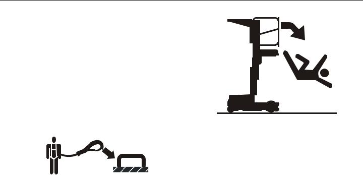
•JLG Industries, Inc. recommends that the operator utilize a fall restraint system in the platform with a maximum 30 inch (76 cm) lanyard attached to an authorized lanyard anchorage point. For further information regarding fall protection requirements on JLG products, contact JLG Industries, Inc.
•Before operating the machine, make sure all railing and gates are fastened in their proper position.
•Keep both feet firmly positioned on the platform floor at all times. Never use ladders, boxes, steps, planks, or similar items on platform to provide additional reach.
•Never use the mast assembly to enter or leave the platform.
•Use extreme caution when entering or leaving platform. Ensure that the mast assembly is fully lowered. Face the machine when entering or leaving the platform. Always maintain “three point contact” with the machine, using two hands and one foot or two feet and one hand at all times during entry and exit.
1-4 |
– JLG Lift – |
3121227 |
SECTION 1 - SAFETY PRECAUTIONS
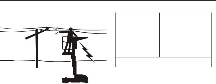
Electrocution Hazards
•This machine is not insulated and does not provide protection from contact or proximity to electrical current.
•Maintain distance from electrical lines, apparatus, or any energized (exposed or insulated) parts according to the Minimum Approach Distance (MAD) as shown in Table 1- 1.
•Allow for machine movement and electrical line swaying.
Table 1-1. Minimum Approach Distances (M.A.D.)
Voltage Range |
MINIMUM APPROACH DISTANCE |
(Phase to Phase) |
in Feet (Meters) |
|
|
0 to 50 KV |
10 (3) |
|
|
Over 50KV to 200 KV |
15 (5) |
|
|
Over 200 KV to 350 KV |
20 (6) |
|
|
Over 350 KV to 500 KV |
25 (8) |
|
|
Over 500 KV to 750 KV |
35 (11) |
|
|
Over 750 KV to 1000 KV |
45 (14) |
NOTE: This requirement shall apply except where employer, local or governmental regulations are more stringent.
•Maintain a clearance of at least 10 ft. (3m) between any part of the machine and its occupants, their tools, and their equipment from any electrical line or apparatus carrying up to 50,000 volts. One foot additional clearance is required for every additional 30,000 volts or less.
•The minimum approach distance may be reduced if insulating barriers are installed to prevent contact, and the barriers are rated for the voltage of the line being guarded. These barriers shall not be part of (or attached to) the machine. The minimum approach distance shall be reduced to a distance within the designed working dimensions of the insulating barrier. This determination shall be
3121227 |
– JLG Lift – |
1-5 |
SECTION 1 - SAFETY PRECAUTIONS
made by a qualified person in accordance with the employer, local, or governmental requirements for work practices near energized equipment
DO NOT MANEUVER MACHINE OR PERSONNEL INSIDE PROHIBITED ZONE (MAD). ASSUME ALL ELECTRICAL PARTS AND WIRING ARE ENERGIZED UNLESS KNOWN OTHERWISE.
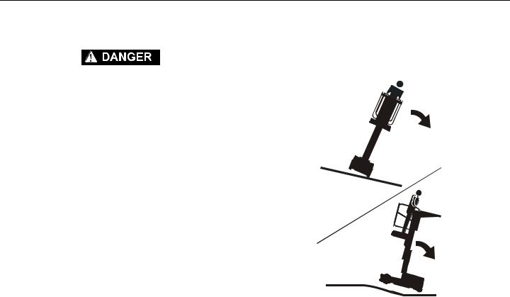
Tipping Hazards
•The user should be familiar with the surface before driving. Do not exceed the allowable sideslope and grade while driving.
1-6 |
– JLG Lift – |
3121227 |
SECTION 1 - SAFETY PRECAUTIONS
•Do not elevate platform or drive with platform elevated while on a slope, or on an uneven or soft surface.
•Before driving on floors, bridges, trucks, and other surfaces, check allowable capacity of the surfaces.
•Never exceed the maximum platform capacity. Distribute loads evenly on platform floor and material tray.
•Keep the chassis of the machine a minimum of 2 ft. (0.6m) from holes, bumps, drop-offs, obstructions, debris, concealed holes, and other potential hazards at the ground level.
•Never attempt to use the machine as a crane. Do not tieoff machine to any adjacent structure.
•Do not increase the platform size with unauthorized deck extensions or attachments, increasing the area exposed to wind will decrease stability.
•If mast assembly or platform is caught so that one or more wheels are off the ground, the operator must be removed before attempting to free the machine. Use cranes, forklift trucks, or other appropriate equipment to stabilize machine and remove personnel.
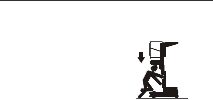
Crushing And Collision Hazards
•Personal protection equipment must be worn by all operating and ground personnel.
•Check work area clearances above, on sides, and bottom of platform while driving and lifting or lowering platform.
•During operation, keep all body parts inside platform railing.
•Always post a lookout when driving in areas where vision is obstructed.
3121227 |
– JLG Lift – |
1-7 |

SECTION 1 - SAFETY PRECAUTIONS
• Keep non-operating personnel at least 6 ft. (1.8m) away |
1.4 LIFTING, AND HAULING |
from machine during all driving operations. |
|
•Limit travel speed according to conditions of ground surface, congestion, visibility, slope, location of personnel, and other factors causing hazards of collision or injury to personnel.
•Be aware of stopping distances in all drive speeds.
•Do not drive at high speeds in restricted or close quarters or when driving in reverse.
•Exercise extreme caution at all times to prevent obstacles from striking or interfering with operating controls and persons in the platform.
•Ensure that operators of other overhead and floor level machines are aware of the aerial work platform’s presence. Disconnect power to overhead cranes.
•Warn personnel not to work, stand, or walk under a raised platform. Position barricades on floor as necessary.
General
•Never allow personnel in platform while lifting, or hauling.
•This machine should not be towed in the event of emergency, malfunction, power failure, or loading/unloading. Lift only with a fork lift truck using the designated fork lift pockets in the machine’s base frame.
•Ensure platform is fully retracted and completely empty of tools prior to lifting or hauling.
•When lifting machine with a forklift, position forks only at designated areas of the machine. Lift with a forklift of adequate capacity.
•Refer to the Machine Operation section of this manual for lifting information.
1-8 |
– JLG Lift – |
3121227 |

SECTION 2 - PREPARATION AND INSPECTION
SECTION 2. PREPARATION AND INSPECTION
2.1PERSONNEL TRAINING
The aerial platform is a personnel handling device; so it is necessary it be operated and maintained only by trained personnel.
Persons under the influence of drugs or alcohol or who are subject to seizures, dizziness or loss of physical control must not operate this machine.
Operator Training
Operator training must cover:
1.Use and limitations of the controls in the platform and at the ground, emergency controls and safety systems.
2.Control labels, instructions, and warnings on the machine.
3.Rules of the employer and government regulations.
4.Use of approved fall protection device.
5.Enough knowledge of the mechanical operation of the machine to recognize a malfunction or potential malfunction.
6.The safest means to operate the machine where overhead obstructions, other moving equipment, and obstacles, depressions, holes, drop-offs are present.
7.Means to avoid the hazards of unprotected electrical conductors.
8.Specific job requirements or machine application.
3121227 |
– JLG Lift – |
2-1 |

SECTION 2 - PREPARATION AND INSPECTION
Training Supervision
Training must be done under the supervision of a qualified person in an open area free of obstructions until the trainee has developed the ability to safely control and operate the machine.
Operator Responsibility
The operator must be instructed that he/she has the responsibility and authority to shut down the machine in case of a malfunction or other unsafe condition of either the machine or the job site.
NOTE: The Manufacturer or Distributor will provide qualified people for training assistance with the first unit(s) delivered and from that time forward as requested by the user or his/her personnel.
2.2PREPARATION, INSPECTION, AND MAINTENANCE
The following Table 2-1 on page 2-3, covers the periodic machine inspections and maintenance recommended by JLG Industries, Inc. Consult local regulations for further requirements for aerial work platforms.
The frequency of inspections and maintenance must be increased as necessary when the machine is used in a harsh or hostile environment, if the machine is used with increased frequency, or if the machine is used in a severe manner.
2-2 |
– JLG Lift – |
3121227 |
SECTION 2 - PREPARATION AND INSPECTION
Table 2-1. Inspection and Maintenance Table
TYPE |
FREQUENCY |
PRIMARY |
SERVICE |
REFERENCE |
|
RESPONSIBILITY |
QUALIFICATION |
||||
|
|
|
|||
|
|
|
|
|
|
Pre-Start Inspection |
Before using each day; or |
User or Operator |
User or Operator |
Operator and Safety |
|
|
whenever there’s an Opera- |
|
|
Manual |
|
|
tor change. |
|
|
|
|
|
|
|
|
|
|
Pre-Delivery |
Before each sale, lease, or |
Owner, Dealer, or User |
Qualified JLG Mechanic |
Service and Maintenance |
|
Inspection |
rental delivery. |
|
|
Manual and applicable JLG |
|
(See Note) |
|
|
|
inspection form |
|
|
|
|
|
|
|
Frequent |
In service for 3 months or |
Owner, Dealer, or User |
Qualified JLG Mechanic |
Service and Maintenance |
|
Inspection |
150 hours, whichever |
|
|
Manual and applicable JLG |
|
|
comes first; or; |
|
|
inspection form |
|
|
Out of service for a period of |
|
|
|
|
|
more than 3 months; or |
|
|
|
|
|
Purchased used. |
|
|
|
|
|
|
|
|
|
|
Annual Machine Inspec- |
Annually, no later than 13 |
Owner, Dealer, or User |
Qualified JLG Mechanic |
Service and Maintenance |
|
tion |
months from the date of prior |
|
(Recommended) |
Manual and applicable JLG |
|
|
inspection. |
|
|
inspection form |
|
|
|
|
|
|
|
Preventative |
At intervals as specified in |
Owner, Dealer, or User |
Qualified JLG Mechanic |
Service and Maintenance |
|
Maintenance |
the Service and Maintenance |
|
|
Manual |
|
|
Manual. |
|
|
|
NOTE: Inspection forms are available from JLG. Use the Service and Maintenance Manual to perform inspections.
3121227 |
– JLG Lift – |
2-3 |
SECTION 2 - PREPARATION AND INSPECTION
2.3 PRE-START INSPECTION |
|
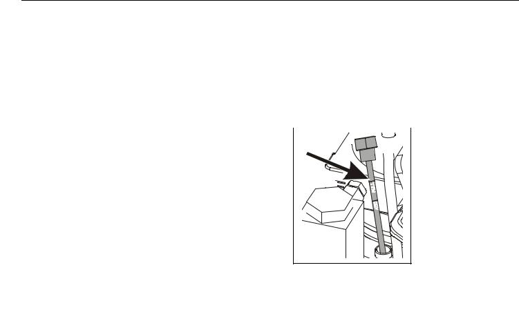
|
a more accurate reading on the dipstick. Once the |
||||||||||
|
|
|
hydraulic oil is warmed check the dipstick reading, it |
||||||||||
The Pre-Start Inspection should include each of the following: |
|
|
should be up to or close to the FULL line on the dipstick. |
||||||||||
|
|
|
|
|
|
|
|
|
|
|
|
||
1. Cleanliness – Check all surfaces for leakage (hydraulic |
|
|
• DO NOT FILL PAST THE FULL LINE. |
||||||||||
|
|
|
|
|
|
|
|
|
|
|
|
||
oil or battery fluid) or foreign objects. Report any leak- |
|
|
• ALWAYS ADD oil if level is at or below the ADD line. |
||||||||||
age to the proper maintenance personnel. |
NOTE: If hydraulic oil is to be added, CHECK THE HYDRAULIC |
||||||||||||
2. Decals and Placards – Check all for cleanliness and |
|||||||||||||
|
|
OIL DECAL located on the right side frame, opposite the |
|||||||||||
legibility. Make sure no decals or placards are missing. |
|
|
|||||||||||
|
|
pump assembly, for hydraulic oil type and specification. |
|||||||||||
Make sure all illegible decals and placards are cleaned |
|
|
|||||||||||
|
|
DO NOT OVERFILL. |
|||||||||||
or replaced. (Reference "Decal Installations" in Section |
|
|
|||||||||||
|
|
|
|
|
|
|
|
|
|
|
|
||
3). |
|
|
|
|
|
|
|
|
|
|
|
The hydraulic oil level in |
|
|
|
|
|
|
|
|
|
|
|
|
|||
|
|
|
|
|
|
|
|
|
|
|
|
||
3. Operation and Safety Manuals – Make sure a copy of |
|
|
|
|
|
|
|
|
|
|
|
the reservoir located on |
|
|
|
|
|
|
|
|
|
|
|
|
|||
the Operator and Safety Manual, EMI Safety Manual |
|
|
|
|
|
|
|
|
|
|
|
the hydraulic pump |
|
|
|
|
|
|
|
|
|
|
|
|
|||
(ANSI/CSA Spec only), and ANSI Manual of Responsi- |
|
|
|
|
|
|
|
|
|
|
|
assembly should read to |
|
|
|
|
|
|
|
|
|
|
|
|
|||
bilities (ANSI/CSA Spec only) is enclosed in the weather |
|
|
|
|
|
|
|
|
|
|
|
or close to the FULL LINE |
|
resistant storage container. |
|
|
|
|
|
|
|
|
|
|
|
on the Hydraulic Reser- |
|
|
|
|
|
|
|
|
|
|
|
|
|||
|
|
|
|
|
|
|
|
|
|
|
|||
4. Daily Walk-Around Inspection – (See Section 2.4 on |
|
|
|
|
|
|
|
|
|
|
|
voir dip stick when |
|
|
|
|
|
|
|
|
|
|
|
|
hydraulic oil is at operat- |
||
page 2-5) |
|
|
|
|
|
|
|
|
|
|
|
ing temperature. |
|
|
|
|
|
|
|
|
|
|
|
|
|||
|
|
|
|
|
|
|
|
|
|
|
|
||
5. Battery – Charge as required (See Section 3.5 on page 3-5).
6. Hydraulic Oil – The hydraulic oil level in the pump reservoir can vary with oil temperature, i.e a machine that is cold the oil level may not be up to the FULL line on the dipstick. Cycle the mast up and down a few times to get
2-4 |
– JLG Lift – |
3121227 |

SECTION 2 - PREPARATION AND INSPECTION
7.Function Check - Check all machine controls for operation. (See Section 2.5 on page 2-8)
If optional equipment is installed on this machine refer to Section 3 for specific Pre-Start Inspection and Operation instructions.
2.4DAILY WALK-AROUND INSPECTION
Begin the “Walk-Around Inspection” at item one (1) as noted on the diagram (See Figure 2-1. on page 2-6). Continue around machine checking each item in sequence for the conditions listed in the following check list.
TO AVOID POSSIBLE INJURY, BE SURE MACHINE POWER IS “OFF” DURING “WALK-AROUND INSPECTION”.
DO NOT OPERATE MACHINE UNTIL ALL MALFUNCTIONS HAVE BEEN CORRECTED.
DO NOT OVERLOOK VISUAL INSPECTION OF THE BASE FRAME UNDERSIDE. CHECK THIS AREA FOR OBJECTS OR DEBRIS WHICH COULD CAUSE EXTENSIVE MACHINE DAMAGE.
3121227 |
– JLG Lift – |
2-5 |

SECTION 2 - PREPARATION AND INSPECTION
9
10
8
7
6
5
4
3
2
1
Figure 2-1. Daily Walk-Around Inspection for 10MSP Machines.
2-6 |
– JLG Lift – |
3121227 |

SECTION 2 - PREPARATION AND INSPECTION
Walk-Around Inspection Components
Reference - Figure 2-1. on page 2-6
NOTE: On all components, make sure there are no loose or missing parts, they are securely fastened, no visible damage, leaks or excessive wear exists in addition to any other criteria mentioned.
1.Front Caster Wheels - Check for any debris stuck to or around wheels.
2.Base Frame - Check for loose wires or cables dangling below the base.
3.Batteries (one each side of machine) - Not leaking; battery cables secure to posts; no corrosion.
4.Rear Drive Wheels - Check for any debris stuck to or around wheels.
5.Mast Assembly - Mast sections; slide pads; mast chains; sequencing cables; platform control and power cables (on side of mast); power cables properly tensioned and seated in sheaves; cable sheaves rotating freely.
6.Motor/Pump/Reservoir Unit - No evidence of hydraulic leaks. Hydraulic oil level should be filled level with the full line on the dip stick.
7.Ground Control Station - Main Power Switch (Key) operable; placards secure and legible; emergency stop switch operates properly.
8.Manual Descent Control Valve - See note before item- 1.
9.Platform Control Console - Platform control; placards secure and legible; emergency stop switch reset for operation; Control markings legible.
10.Platform Assembly and Gate - Platform railings; entry gate in proper working order, closing properly.
3121227 |
– JLG Lift – |
2-7 |
SECTION 2 - PREPARATION AND INSPECTION
2.5FUNCTION CHECK
Once the “Walk-Around” Inspection is complete, perform a function check of all systems in an area free of overhead and ground level obstructions. Refer to Section 3 this manual, for more specific operating instructions.
IF THE MACHINE DOES NOT OPERATE PROPERLY, TURN OFF THE MACHINE IMMEDIATELY! REPORT THE PROBLEM TO THE PROPER MAINTENANCE PERSONNEL. DO NOT OPERATE THE MACHINE UNTIL IT IS DECLARED SAFE FOR OPERATION.
Function Check Items:
1.From the ground controls with no load in the platform:
a.Operate ground control functions, platform lift up and lower.
b.Ensure all machine functions are disabled when the Emergency Stop Button is activated (pressed in).
c.Check Manual Descent Control valve is operating properly. (Located under hood)
2.From the platform control console:
a.Ensure the control console is properly mounted and secure.
b.Raise and lower platform 2 ft. to 3 ft. (.61m to.92 m) several times. Check for smooth elevation and lowering of platform.
c.Operate all functions, check all limit, cut-out, and enable switches are functioning properly:
•Machine Brakes - Drive the machine on a grade, (do not exceed the rated gradeability), and stop to ensure the brakes hold.
•Tilt Warning Limit - With the platform completely lowered, drive the machine onto a surface with a tilt of more than 1.5° in any direction
(do not exceed rated gradeability). The machine will indicate a tilt condition if any attempt is made to elevate the platform.
•Drive Speed Reduction Limit - When platform is elevated more than 1.5 to 2 ft. (.5m) drive speed is cut to 1/4 of platform lowered drive speed.
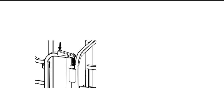
•Platform Gate Open Limit - If either side platform gate is open during machine operation, the machine will stop and will display a fault code at the Ground Control Module and Platform Con-
2-8 |
– JLG Lift – |
3121227 |
SECTION 2 - PREPARATION AND INSPECTION
sole. (Australian Spec machines also include a platform gate lock/release lever mechanism on top of each gate that must be pressed down to open the platform gate. Check that the lock/ release on each gate is latching properly when gate is closed, and releasing when the handle lever is depressed.)
Platform Gate Lock/Release Lever
(Australian Spec Machines Only)
•Platform Joystick Enable and Footswitch Enable - The machine will not operate (drive or lift) unless both of these switches are pressed and held during drive or lift operation.
d.Ensure all machine functions are disabled when the Emergency Stop Button is activated (pressed in).
3121227 |
– JLG Lift – |
2-9 |

SECTION 2 - PREPARATION AND INSPECTION
 NOTES:
2-10 |
– JLG Lift – |
3121227 |

SECTION 3 - MACHINE OPERATION
SECTION 3. MACHINE OPERATION
3.1 GENERAL
THE MANUFACTURER HAS NO DIRECT CONTROL OVER MACHINE APPLICATION AND OPERATION. THE USER AND OPERATOR ARE RESPONSIBLE FOR CONFORMING WITH GOOD SAFETY PRACTICES.
This section provides the necessary information needed to understand control function and operation.
3.2 MACHINE DESCRIPTION
The JLG 10MSP Lift is an electric powered self-propelled machine with an aerial work platform mounted to an elevating mast mechanism. The personnel lift’s intended purpose is to provide personnel access to areas above ground level.
The primary control console is located in the platform. From the Platform Control Console the operator can drive the machine and raise or lower the platform.
The machine is rear wheel drive and provide steering with freewheeling front caster wheels.
The controls of the programmable Ground Control Station are to be used during machine power-up, maintenance, function checks, or in case of emergency, should the operator in the platform be unable to lower the platform.
Vibrations emitted by these machines are not hazardous to an operator working in the platform.
The continuous A-Weighted sound pressure level at the work platform is less than 70db (A).
3121227 |
– JLG Lift – |
3-1 |
Loading...