


10MSP
Table of contents
 Loading...

3121229 10MSP 3


TABLE OF CONTENTS
3121229 10MSP 5
SECTION 1 - BASE.............................................................................................................................................................................. 7
FIGURE 1-1. BASE MOUNTED COMPONENTS INSTALLATION .................................................................................................. 8
FIGURE 1-2. DRIVE ASSEMBLY ................................................................................................................................................... 12
FIGURE 1-3. COVERS AND TIE-DOWNS INSTALLATION .......................................................................................................... 14
SECTION 2 - CONTROLS ................................................................................................................................................................. 17
FIGURE 2-1. PUMP MOTOR ASSEMBLY AND INSTALLATION .................................................................................................. 18
FIGURE 2-2. BATTERY CHARGER AND PLUG INSTALLATION (Prior to SN 0130010886) ....................................................... 22
FIGURE 2-3. BATTERY CHARGER AND PLUG INSTALLATION (SN 0130010886 to Present) .................................................. 24
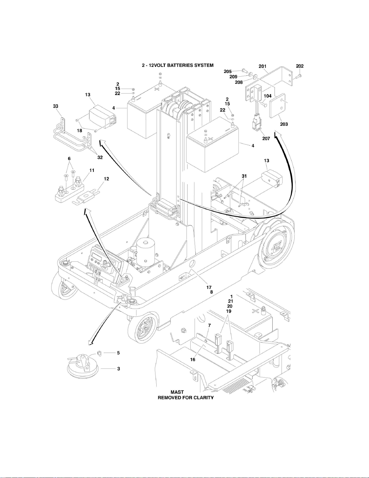
FIGURE 2-4. BATTERIES, SWITCHES, HORN AND BEACON LIGHT INSTALLATION .............................................................. 28
FIGURE 2-5. GROUND COMPONENTS INSTALLATIONS ........................................................................................................... 32
FIGURE 2-6. PLATFORM CABLES AND CONTROLS INSTALLATION ........................................................................................ 34
FIGURE 2-7. CONTROL BOX ASSEMBLY .................................................................................................................................... 36
SECTION 3 - MAST ........................................................................................................................................................................... 39
FIGURE 3-1. MAST ASSEMBLY AND INSTALLATION ................................................................................................................. 40
SECTION 4 - PLATFORM .................................................................................................................................................................. 43
FIGURE 4-1. PLATFORM INSTALLATION (ALL SPECS TO PRESENT AND AUSTRALIAN SPEC) (Prior to SN 0130018678) . 44
FIGURE 4-2. PLATFORM INSTALLATION (AUSTRALIAN SPEC ONLY) (SN 0130018678 to Present) ...................................... 46
FIGURE 4-3. MATERIAL TRAY INSTALLATION ........................................................................................................................... 48
FIGURE 4-4. OPTIONAL BICYCLE CARRIERS INSTALLATION .................................................................................................. 50
FIGURE 4-5. OPTIONAL RUG CARRIER INSTALLATION ........................................................................................................... 52
FIGURE 4-6. OPTIONAL FLUORESCENT TUBE CADDY ASSEMBLY ........................................................................................ 54
SECTION 5 - CYLINDER ................................................................................................................................................................... 57
FIGURE 5-1. LIFT CYLINDER ASSEMBLY (ORIGINAL EQUIPMENT) (Prior to SN 0130011099) ............................................... 58
FIGURE 5-2. LIFT CYLINDER ASSEMBLY (SERVICE REPLACEMENT) (SN 0130011099 to Present) ...................................... 60
SECTION 6 - HYDRAULIC ................................................................................................................................................................ 63
FIGURE 6-1. HYDRAULIC DIAGRAM ............................................................................................................................................ 64
SECTION 7 - ELECTRICAL ............................................................................................................................................................... 67
FIGURE 7-1. ELECTRICAL COMPONENTS INSTALLATION ....................................................................................................... 68
SECTION 8 - DECALS ....................................................................................................................................................................... 75
FIGURE 8-1. DECAL INSTALLATION ............................................................................................................................................ 76
SECTION 9 - RECOMMENDED SERVICE PARTS STOCK ............................................................................................................. 81
FIGURE 9-1. 10MSP STANDARD PARTS ..................................................................................................................................... 82
FIGURE 9-2. 10MSP VARIABLE PARTS ....................................................................................................................................... 84
SECTION 10 - SPECIAL OPTIONS ................................................................................................................................................... 85
FIGURE 10-1. SPECIAL OPTIONS ................................................................................................................................................ 86
PART NUMBER INDEX ..................................................................................................................................................................... 87


SECTION 1 - BASE
3121229 10MSP 7
SECTION 1 - BASE
SECTION 1 - BASE
8 10MSP 3121229
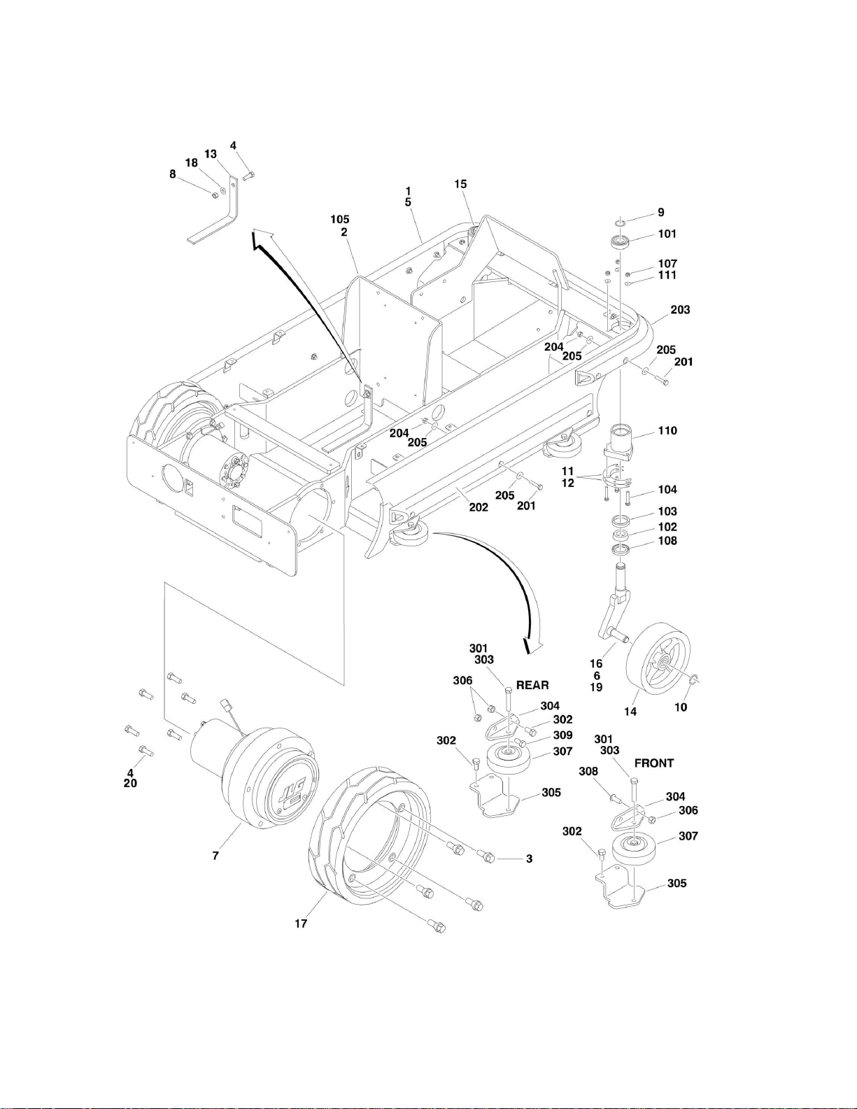
FIGURE 1-1. BASE MOUNTED COMPONENTS INSTALLATION

SECTION 1 - BASE
3121229 10MSP 9
FIGURE 1-1. BASE MOUNTED COMPONENTS INSTALLATION
ITEM
PART NUMBER
QTY
DESCRIPTION
REV
0274893
Ref
BASE ASSEMBLY
F
1
0100081
AR
Compound, Locking
2
0274904
1
Frame Assembly (See Items 101-111 for Breakdown)
3
0630580
10
Bolt, Wheel
4
0641609
13
Bolt 3/8in-16NC x 1-1/8in
5
0940132
1
Bumper, Chassis
6
3020039
AR
Lubricant Loctite #51049
7
3160323
2
Drive Motor Assembly (See DRIVE ASSEMBLY for Breakdown)
8
3311605
1
Locknut 3/8in-16NC
9
3760115
2
Ring, Retaining
10
3760496
2
Ring, Retaining
11
4071113
AR
Shim .015in
12
4071114
AR
Shim .036in
13
4240147
1
Strap, Static
14
Ref
Tire and Wheel Assembly Options:
14
1001098810
2
Tire and Wheel Assembly (was p/n 4520281) (Prior to SN
0130011864)
14
1001098810
2
Tire and Wheel Assembly (SN 0130011864 to Present)
15
4520342
1
Spindle (Left Side)
16
4520343
1
Spindle (Right Side)
17
Ref
Tire and Wheel Assembly Options:
17
1001114467
2
Tire and Wheel Assembly (Was p/n 4520326) (Prior to SN
0130008686)
17
See Note
1
Tire and Wheel Assembly (Note: Tire and Wheel Assemblies
used in this range of SNs vary between old and new style - Use
p/n 1001114467 as replacement.) (SN 0130008685 through
0130009365)
17
1001114467
2
Tire and Wheel Assembly (was p/n 4520565) (SN 0130009366
through 0130011758)
17
1001114467
1
Tire and Wheel Assembly (was p/n 1001100840) (SN
0130011759 through 0130013969)
17
1001114467
2
Tire and Wheel Assembly (SN 0130013970 to Present)
18
4711600
1
Flatwasher 3/8in Narrow
19
8882970
AR
Coating, Clear
20
0100011
AR
Locking Compound
0274904
Ref
FRAME ASSEMBLY
I
101
0440306
2
Bearing, Ball
102
0440307
2
Bearing, Roller
103
0440308
2
Bearing, Race
104
0641413
6
Bolt 1/4in-20NC x 1-5/8in
105
2360750
1
Frame
106
3020029
AR
Grease (Not Shown)
107
3271405
6
Locknut 1/4in-20NC
108
3960590
2
Seal
110
4341155
2
Mount, Caster
111
4711400
6
Flatwasher 1/4in Narrow
0274078
Ref
BUMPERS INSTALLATION (OPTIONAL)
C
201
0641408
13
Bolt 1/4in-20NC x 1in
202
0940152
2
Bumper, Side
203
0940153
1
Bumper, Front
204
3311405
13
Locknut 1/4in-20NC

SECTION 1 - BASE
10 10MSP 3121229
ITEM
PART NUMBER
QTY
DESCRIPTION
REV
205
4751400
26
Flatwasher 1/4in Wide
0240103
Ref
GUIDE ROLLER ATTACHMENT (OPTIONAL)
B
301
0100011
AR
Locking Compound
302
0641606
10
Bolt 3/8in-16NC x 3/4in
303
0641617
4
Bolt 3/8in-16NC x 2-1/8in
304
0903120
4
Bracket, Top Roller
305
0903121
4
Bracket, Bottom Roller
306
3311605
8
Locknut 3/8in-16NC
307
4520352
4
Wheel
308
Ref
Hardware Options:
308
0641606
4
Bolt 3/8in-16NC x 3/4in (Prior to SN 0130015906)
308
3900283
4
Screw Button Head 3/8in-16NC x 3/4in (SN 0130015906 to
Present)
309
Ref
Bolt Options:
309
0641606
2
Bolt 3/8in-16NC x 3/4in (Prior to SN 0130015906)
309
0641609
2
Bolt 3/8in-16NC x 1-1/8in (SN 0130015906 to Present)

SECTION 1 - BASE
12 10MSP 3121229
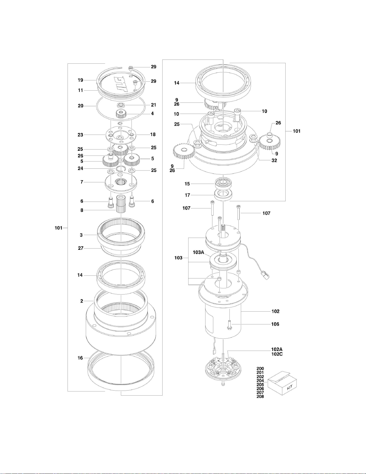
FIGURE 1-2. DRIVE ASSEMBLY

SECTION 1 - BASE
3121229 10MSP 13
FIGURE 1-2. DRIVE ASSEMBLY
ITEM
PART NUMBER
QTY
DESCRIPTION
REV
3160323
Ref
SPINDLE/HUB ASSEMBLY
1
3160323
1
Spindle
2
7024756
1
Hub
3
7024758
1
Ring, Input
4
70000210
1
Gear, Input Sun
5
70000210
3
Gear, Input Planet
6
70000210
3
Pin, Input Planet
7
70000210
1
Carrier
8
70000210
1
Gear, Output Sun
9
70000212
3
Gear, Output Planet
10
70000212
3
Pin, Output Planet
11
7024747
1
Cover
14
See Note
2
Bearing (Note: Use Items 201, 203, 205 & 206)
16
See Note
1
Seal, Lip (Note: Use Items 201 & 205)
17
70000215
1
Seal, Lip
18
70000210
3
Ring, Retaining
19
7024747
1
Ring, Retaining
20
70000191
1
O-Ring
21
7024747
1
Thrustwasher
23
70000210
1
Plate, Thrust
24
70000210
1
Ring, Retaining
25
See Note
6
Thrustwasher (Note: Use Items 202 & 206)
26
See Note
3
Bushing, Planet (Note: Use Items 202 & 206)
27
See Note
1
Ring, Retaining (Note: Use Items 203 & 205)
29
7024747
2
Plug
32
70000212
3
Thrustwasher, Tanged
3160323
Ref
DRIVE MOTOR ASSEMBLY
B
101
3160323
1
Hub/Spindle Assembly (Includes Items 1-32)
102
70000211
1
Electric Motor Assembly
102A
70000213
4
Brush
102B
70000213
1
Indicator, Wear (Not Shown)
102C
70000213
4
Spring, Brush
102D
70000213
1
Bearing (Not Shown)
103
70000214
1
Brake Assembly
103A
70000935
1
Disc, Brake (Part of Kit)
106
70000211
2
Bolt
107
70000214
3
Bolt
Ref
KIT OPTIONS:
Ref
Repair Kit Options:
200
7024747
1
Cover Kit (Includes Items 11, 19-21 & 29)
201
7024748
1
Main Seal and Bearing Kit (Includes Items 14, 16 & 20)
202
70000210
1
Input Carrier Kit (Includes Items 4-8, 18, 20 & 23-26)
203
7024758
1
Input Ring Kit (Includes Items 3, 14, 20 & 27)
204
70000211
1
Motor Kit (Includes Items 17, 102 & 106)
205
7024756
1
Hub Kit (Includes Items 2, 14, 16, 20 & 27)
206
70000212
1
Output Planet Kit (Includes Items 9, 10, 14, 20, 25, 26 & 32)
207
70000213
1
Brush and Bearing Kit (Includes Items 102A-102D)
208
70000214
1
Brake Kit (Includes Items 103 & 107)
SECTION 1 - BASE
14 10MSP 3121229
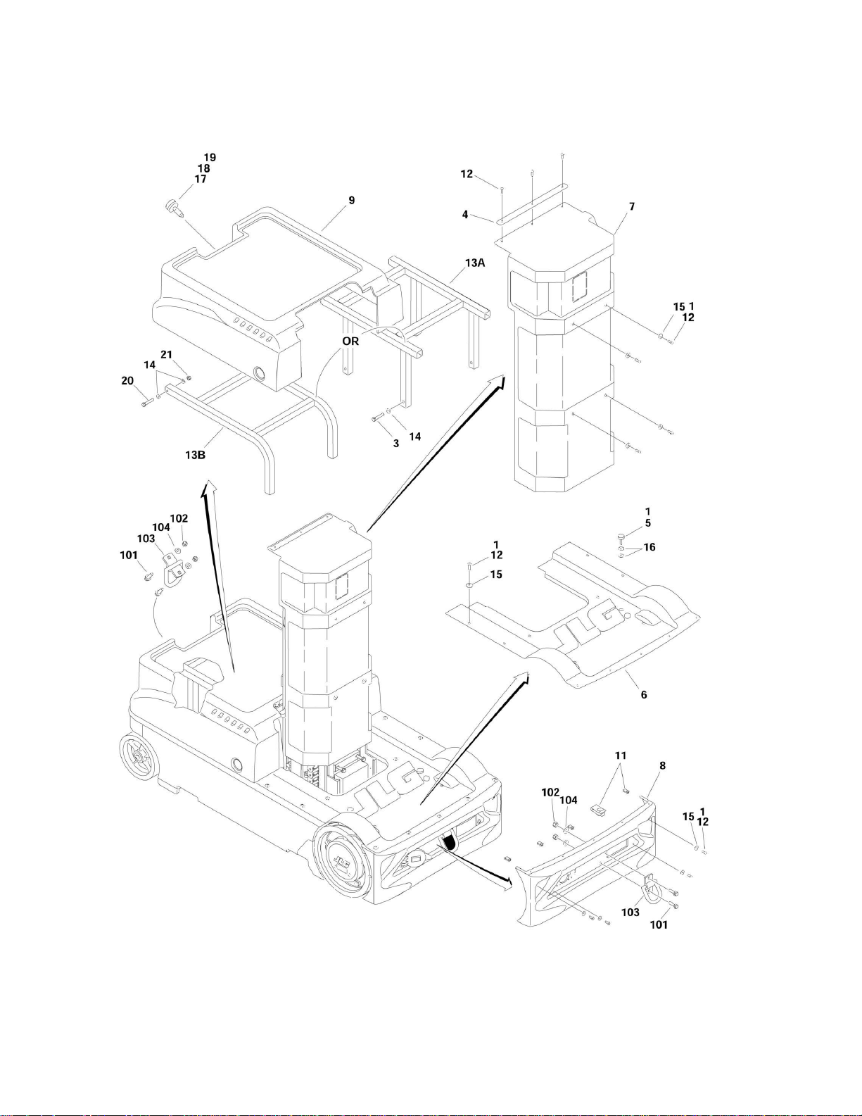
FIGURE 1-3. COVERS AND TIE-DOWNS INSTALLATION

SECTION 1 - BASE
3121229 10MSP 15
FIGURE 1-3. COVERS AND TIE-DOWNS INSTALLATION
ITEM
PART NUMBER
QTY
DESCRIPTION
REV
0274901
Ref
COVER INSTALLATION
C
1
0100011
AR
Locking Compound
3
0641616
4
Bolt 3/8in-16NC x 2in (Prior to SN 0130015319)
4
0903222
1
Brace
5
0940049
2
Stopper, Hood
6
Ref
Cover, Battery and Frame Options:
6
1001120531
1
Cover, Battery and Frame (was p/n 1671141) (Prior to SN
0130015319)
6
1001120531
1
Cover, Battery and Frame (SN 0130015319 to Present)
7
1671143
1
Cover, Mast
8
1671146
1
Cover, Rear Bumper
9
1671298
1
Cover, Front Hood
11
3300454
9
Nut 1/4in-20NC
12
3900258
22
Screw Button Head 1/4in-20NC x 3/4in
13
Ref
Support Options:
13A
4341067
1
Support (Prior to SN 0130015319)
13B
1001121648
1
Support (SN 0130015319 to Present)
14
4711600
4
Flatwasher 3/8in Narrow
15
4751400
19
Flatwasher 1/4in (Wide)
16
4751500
4
Flatwasher 5/16in (Wide)
17
1380169
1
Clip
18
3900174
1
Screw, Thumb
19
3760308
1
Retainer
20
0641617
2
Bolt 3/8in-16NC x 2-1/8in (SN 0130015319 to Present)
21
3311605
2
Locknut 3/8in-16NC (SN 0130015319 to Present)
0240114
Ref
TIE-DOWNS INSTALLATION
A
101
0811610
4
Screw 3/8in-16NC x 1-1/4in
102
3311605
4
Locknut 3/8in-16NC
103
3760365
2
Tie-Ring
104
4711600
4
Flatwasher 3/8in Narrow


SECTION 2 - CONTROLS
3121229 10MSP 17
SECTION 2 - CONTROLS
SECTION 2 - CONTROLS
18 10MSP 3121229
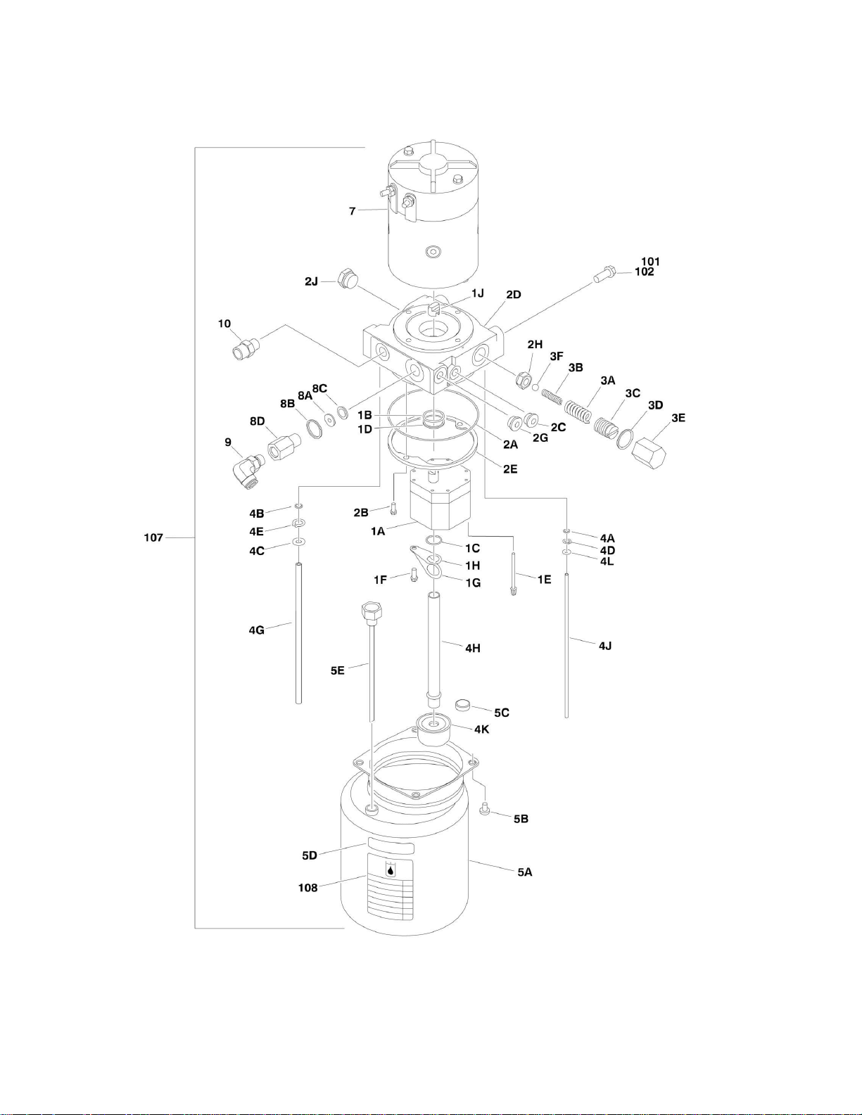
FIGURE 2-1. PUMP MOTOR ASSEMBLY AND INSTALLATION

SECTION 2 - CONTROLS
3121229 10MSP 19
FIGURE 2-1. PUMP MOTOR ASSEMBLY AND INSTALLATION
ITEM
PART NUMBER
QTY
DESCRIPTION
REV
3600392
1
PUMP/MOTOR ASSEMBLY
D
1
7027943
Ref
Pump Components Kit
1A
7027943
1
Pump
1B
7027943
1
Seal
1C
7011021
1
Seal
1D
7027943
1
Seal
1E
7010928
4
Screw
1F
7011033
1
Screw
1G
7027943
1
Lockwasher
1H
7027943
1
Retainer
1J
7011016
1
Coupler
2
7027944
Ref
Adaptor Components Kit
2A
7011025
1
Seal
2B
7011011
2
Screw
2C
7027944
1
Plug
2D
7027944
1
Adaptor
2E
7011013
1
Retainer
2F
7027944
1
Plug, Plastic (Not Shown)
2G
7027944
1
Plug, Steel
2H
7027944
1
Seat Assembly
2J
7027944
1
Plug
3
7027945
Ref
Relief Valve Components Kit
3A
7011008
1
Spring
3B
7011017
1
Spring
3C
7011009
1
Screw, Adjustment
3D
7027945
1
Gasket
3E
7011004
1
Cap
3F
7027945
1
Ball
4
7027946
Ref
Tube Components Kit
4A
7011024
1
Seal
4B
7027946
1
Seal
4C
7027946
1
Washer
4D
7011031
1
Ring, Retaining
4E
7011032
1
Ring, Retaining
4G
7027946
1
Tube
4H
7027946
1
Tube
4J
7027946
1
Tube
4K
7011029
1
Strainer
4L
7011034
1
Spacer
5
7027947
Ref
Tank Components Kit
5A
7027947
1
Tank
5B
7027947
4
Screw
5C
7011027
1
Magnet
5D
7027947
1
Label
5E
7011069
1
Breather/Dipstick
6
See Note
1
Label (Not Shown) (Note: Not Available for Purchase)
7
7027948
1
Motor Assembly
7
7027948
1
Brush Kit
8
7027949
Ref
Return Port Components Kit
8A
7027949
1
Seal

SECTION 2 - CONTROLS
20 10MSP 3121229
ITEM
PART NUMBER
QTY
DESCRIPTION
REV
8B
7027949
1
Seal
8C
7027949
1
Washer
8D
7027949
1
Body, Return Port
9
2221185
1
Fitting, 90
10
2110606
1
Fitting, Straight
Ref
PUMP/MOTOR INSTALLATIONS
0273546
Ref
Standard Hydraulic Oil
E
0274181
Ref
Fire Resistant Hydraulic Oil
A
101
0100011
Locking Compound
102
0641606
Bolt 3/8in-16NC x 3/4in
107
3600392
1
Pump/Motor Assembly (See Items 1-10 for Breakdown)
108
1704412
1
Decal - Hydraulic Oil (Stamp Appropriately)
109
Ref
Oil, Hydraulic Options (Not Shown):
109
2300021
1.2 gals
Standard Hydraulic Oil
109
2300014
1.2 gals
Fire Resistant Hydraulic Oil

SECTION 2 - CONTROLS
22 10MSP 3121229
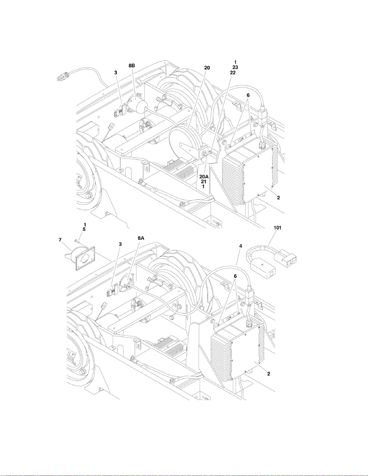
FIGURE 2-2. BATTERY CHARGER AND PLUG INSTALLATION (Prior to SN 0130010886)

SECTION 2 - CONTROLS
3121229 10MSP 23
FIGURE 2-2. BATTERY CHARGER AND PLUG INSTALLATION (Prior to SN 0130010886)
ITEM
PART NUMBER
QTY
DESCRIPTION
REV
Ref
BATTERY CHARGER INSTALLATIONS
0274897
Ref
ANSI - Charger with Plug
C
0274898
Ref
Australian - Charger without Plug
B
0274899
Ref
ANSI - Charger without Plug
C
0274900
Ref
ANSI - Charger with Plug/Cord Reel
C
1
0100011
AR
Locking Compound
2
0400241
1
Battery Charger Assembly (No Serviceable Parts Available)
3
0610131
1
LED Board
4
1060689
1
Cord, Electrical
5
3911016
4
Screw #10-24NC x 1in
5
3311001
2
Nut #10-24NC (Charger with Australian Plug Only)
6
4191706
4
Screw 6mm x 12mm
7
Ref
Cover, Terminal Options:
7
4460802
1
Charger with Plug
7
4460802
1
Charger without Plug
7
Not Required
0
Charger with Plug/Cord Reel
8
Ref
Terminal, Inlet Options:
8A
4460803
1
Charger with ANSI Plug
8A
4460940
1
Charger with Australian Plug
8A
Not Required
0
Charger without Plug
8B
4120046
1
Socket, Cord Reel Stop (Charger with ANSI Plug/Cord Reel
Only)
Ref
Note: Items 20-23 used with Charger with Plug/Cord Reel
only.
20
3680057
1
Reel, Charger Cord
20A
0791508
1
Screw 5/16in-18NC x 1in
21
4751500
1
Flatwasher 5/16in Wide
22
0791406
1
Screw 1/4in-20NC x 3/4in
23
3575423
1
Angle, Mounting
101
2915230
1
BATTERY CHARGER REPROGRAM CONTROLLER KIT (was
p/n 1600466)
SECTION 2 - CONTROLS
24 10MSP 3121229
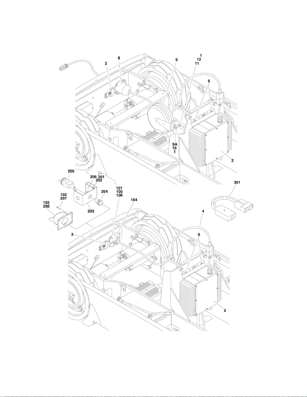
FIGURE 2-3. BATTERY CHARGER AND PLUG INSTALLATION (SN 0130010886 to Present)

SECTION 2 - CONTROLS
3121229 10MSP 25
FIGURE 2-3. BATTERY CHARGER AND PLUG INSTALLATION (SN 0130010886 to Present)
ITEM
PART NUMBER
QTY
DESCRIPTION
REV
Ref
BATTERY CHARGER INSTALLATIONS
0274898
Ref
ANSI/ANSI Export - Charger without Plug
F
0274900
Ref
ANSI - Charger with Plug/Cord Reel
F
1
0100011
AR
Locking Compound
2
Ref
Battery Charger Assembly Options (No Serviceable Parts
Available):
2
1001110117
1
Battery Charger Assembly (was p/n 0400241) (SN 0130010886
through 0130013544)
2
1001102932
1
Battery Charger Assembly (SN 0130013545 through
0130016979)
2
1001136381
1
Battery Charger Assembly (SN 0130016980 to Present)
3
0610131
1
LED Board
4
1060689
1
Cord, Electrical
6
4191706
4
Screw 6mm x 12mm
8
4120046
1
Terminal, Inlet Socket, Cord Reel Stop (Charger with ANSI
Plug/Cord Reel Only)
Ref
Note: Items 9-12 used with Charger with Plug/Cord Reel
only.
9
3680057
1
Reel, Charger Cord
9A
0791508
1
Screw 5/16in-18NC x 1in
10
4751500
1
Flatwasher 5/16in Wide
11
0791406
1
Screw 1/4in-20NC x 3/4in
12
3575423
1
Angle, Mounting
Ref
CHARGER PLUG INSTALLATIONS (ANSI/ ANSI EXPORT/
AUSTRALIAN SPECS)
1001097449
Ref
Charger Plug 110V (ANSI/ ANSI Export/ CSA/ Japanese Spec)
B
1001097455
Ref
Charger Plug 220V (Australian Spec)
C
1001097456
Ref
Charger Plug No Plug (ANSI Export Spec)
A
101
0100011
AR
Locking Compound
102
3911016
AR
Screw #10-24NC x 1in
103
4460802
1
Cover, Terminal
104
Ref
Terminal, Inlet Options:
104
4460803
1
1001097449 Installation
104
4460940
1
1001097455 Installation
104
Not Required
0
1001097456 Installation
105
3311001
2
Nut #10-24NC (1001097455 Installation Only)
106
4761000
2
Lockwasher #10 (1001097455 Installation Only)
Ref
CHARGER PLUG INSTALLATIONS (CE SPECS ONLY)
1001097450
Ref
Charger Plug 220V Post Ground
B
1001097451
Ref
Charger Plug 220V Side Ground
B
1001097452
Ref
Charger Plug 220V Keyed Ground
B
1001097453
Ref
Charger Plug 110V IEC 60309 Yellow
B
1001097454
Ref
Charger Plug 110V IEC 60309 Blue
B
1001097456
Ref
Charger Plug No Plug
A
201
0100011
AR
Locking Compound
202
0721004
4
Screw #10-24NC x 1/2in
203
3571584
1
Plate, Plug Inlet
204
4460428
1
Connector, Strain Relief
205
Ref
Terminal, Male Options:
205
4461202
1
1001097450 Installation
205
4461205
1
1001097451 Installation

SECTION 2 - CONTROLS
26 10MSP 3121229
ITEM
PART NUMBER
QTY
DESCRIPTION
REV
205
4461249
1
1001097452 Installation
205
4461196
1
1001097453 Installation
205
4461199
1
1001097454 Installation
205
Not Required
0
1001097456 Installation
206
4711000
4
Flatwasher #10
207
3911016
AR
Screw #10-24NC x 1in (1001097456 Installation Only)
208
4460802
1
Cover, Terminal (1001097456 Installation Only)
301
2915230
1
BATTERY CHARGER REPROGRAM CONTROLLER KIT (was
p/n 1600466)

SECTION 2 - CONTROLS
28 10MSP 3121229
FIGURE 2-4. BATTERIES, SWITCHES, HORN AND BEACON LIGHT INSTALLATION
Loading...