


A1400
monoblock subwoofer amplifier
OWNER’S MANUAL
Thank you for purchasing a JL Audio amplifier for your automotive sound system.
Your amplifier has been designed and manufactured to exacting standards in order to ensure years of musical enjoyment in your vehicle. For maximum performance and extended warranty
coverage, we highly recommend that you have your new amplifier installed by an authorized JL Audio dealer. Your authorized
dealer has the training, expertise and installation equipment to ensure optimum performance from this product. Should you
decide to install the amplifier yourself, please take the time to read this manual thoroughly so as to familiarize yourself with its installation requirements and setup procedures.
If you have any questions regarding the instructions in this manual or any aspect of your amplifier’s operation, please contact your authorized JL Audio dealer for assistance. If you need further assistance,
please call the JL Audio Technical Support Department at (954) 443-1100 during business hours.

PROTECT YOUR HEARING!
We value you as a long-term customer. For that reason, we urge you to practice restraint in the operation of this product so as not to damage your hearing and that of others in your vehicle. Studies have shown that continuous exposure to high sound pressure levels can lead to permanent (irreparable) hearing loss. This and all other high-power amplifiers are capable of producing such high sound pressure levels when connected to a speaker system. Please limit your continuous exposure to high volume levels.
While driving, operate your audio system in a manner that still allows you to hear necessary noises to operate your vehicle safely (horns, sirens, etc.).
SERIAL NUMBER
In the event that your amplifier requires service or is ever stolen, you will need to have a record of the product’s serial number. Please take the time to enter that number in the space
provided below. The serial number can be found on the bottom panel of the amplifier and on the amplifier packaging.
Serial Number:
INSTALLATION APPLICATIONS
This amplifier is designed for operation in vehicles with 12 volt, negative-ground electrical systems. Use of this product in vehicles with positive ground and/or voltages other than 12V may result in damage to the product and will void the warranty.
This product is not certified or approved for use in aircraft.
Do not attempt to “bridge” the outputs of this amplifier with the outputs of a second amplifier, including an identical one.
Chassis Ground
Connector
(pg. 5)
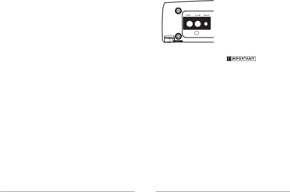
+12 V Power |
Remote Turn-On |
Connector |
Connector |
(pg. 5) |
(pg. 6) |
Input Voltage |
|
Left & Right |
Protection Status |
Bass EQ |
Filter Mode |
|||
Selection |
Preamp Output Jacks |
Indicator |
|
On/O Switch |
Selection |
|||
(pg. 6) |
|
(pg. 8) |
|
(pg. 9) |
Jack for |
(pg. 8) |
|
(pg. 7) |
|
|
Power Status |
|
Input Sensitivity |
Filter |
|||
|
Left & Right |
Remote Bass |
|
|||||
Preamp Input Jacks |
Indicator |
|
Control Knob |
|
Control |
Frequency Selector |
||
|
(pg. 6) |
|
(pg. 9) |
|
(pg. 8) |
|
(pg. 6) |
(pg. 7) |
Input Voltage
Low | High
CH 1 (Left) |
Pre-Outs |
|
|
Power |
Protect |
CH 2 (Right) |
|
|
Bass Boost Controls |
|
|
Filter Freq. (Hz) |
||
Bass Boost |
Input Sens. |
LP Filter |
|
65 |
|
55 |
80 |
||||
|
|
|
|||
|
|
|
45 |
100 |
|
|
|
|
40 |
200 |
|
Remote |
|
|
|
|
|
Bass Port |
|
|
|
|
|
PLANNING YOUR INSTALLATION
It is important that you take the time to read this manual and that you plan out your installation carefully. The following are some considerations that you must take into account when planning your installation.
Cooling Efficiency Considerations:
The outer shell of your JL Audio amplifier is designed to remove heat from the amplifier circuitry. For optimum cooling performance, this outer shell should be exposed to as large a
volume of air as possible. Enclosing the amplifier in a small, poorly ventilated chamber can
lead to excessive heat build-up and degraded performance. If an installation calls for an enclosure around the amplifier, we recommend that this enclosure be ventilated with the aid of a fan. In normal applications, fan-cooling
is not necessary.
Speaker Outputs
(pg. 8)
Mounting the amplifier upside down is strongly discouraged.
If mounting the amplifier under a seat, make sure there is at least 1 inch (2.5 cm) of space above the amplifier’s outer shell to permit proper cooling.
Safety Considerations:
Your amplifier needs to be installed in a dry, well-ventilated environment and in a manner which does not interfere with your vehicle’s safety equipment (air bags, seat belt systems, ABS brake systems, etc.). You should also take the time to securely mount the amplifier using the supplied screws so that it does not come loose in the event of a collision or a sudden jolt to the vehicle.
Stupid Mistakes to Avoid
•Check before drilling any holes in your vehicle to make sure that you will not be drilling through a gas tank, brake line, wiring harness or other vital vehicle system.
•Do not run system wiring outside or underneath the vehicle. This is an extremely dangerous practice which can result in severe damage to your vehicle and person.
•Protect all system wires from sharp metal edges and wear by carefully routing them, tying them down and using grommets and loom where appropriate.
•Do not mount the amplifier in the engine compartment, under the vehicle, on the roof or in any other area that will expose the amplifier circuitry to the elements.
2 |
JL AUDIO A1400 |
JL AUDIO A1400 |
3 |
PRODUCT DESCRIPTION
The JL Audio A1400 is a monoblock subwoofer amplifier utilizing proprietary and patented Class D technology. Its frequency response
is limited to the range below 250 Hz. It is not designed for driving midrange speakers or tweeters. Every aspect of its operation has been optimized for low-frequency amplification. For detailed specifications, please refer to Appendix C (page 13).
TYPICAL INSTALLATION SEQUENCE
The following represents the sequence for a typical amplifier installation, using an aftermarket source unit or OEM Interface processor (like the CleanSweep CL441dsp).
Additional steps and different procedures may be required in some applications. If you have any questions, please contact your authorized JL Audio dealer for assistance.
1)Disconnect the negative battery post connection and secure the disconnected cable to prevent accidental re-connection during installation. This step is not optional.
2)Run power wire (minimum 4 AWG) from the battery location to the amplifier mounting location, taking care to route it in such a
way that it will not be damaged and will not interfere with vehicle operation. Use 4 AWG or larger power wire and a power distribution block if additional amplifiers are being installed with the A1400.
3)Connect power wire to the positive battery post. Fuse the wire with an appropriate fuse block (and connectors) within 18 inches (45 cm) wire length of the positive battery post.
This fuse is essential to protect the vehicle. Do not install the fuse until the power wire has been securely connected to the amplifier.
4)Run signal cables and remote turn-on wire from the source unit to the final amplifier mounting location.
5)Run speaker cables from the speaker systems to the amplifier mounting location.
6)Find a good, solid metal grounding point close to the amplifier and connect the negative power wire to it using appropriate hardware (use of the JL Audio ECS master ground lug, XA-MGL-1 is recommended). Use the same size power wire as the wire connected to the “+12VDC” connection (minimum 4 AWG), no longer than 36 inches (90 cm) from the amplifier to the ground connection point. In some vehicles, it may be necessary to upgrade the battery ground wire. (See page 5 for important notice).
7)Securely mount the amplifier using the supplied screws.
8)Connect the positive and negative power wires to the amplifier. A fuse near the amplifier is not necessary.
9)Connect the remote turn-on wire to the amplifier.
10)Connect the input cables to the amplifier.
11)Connect the speaker cables to the amplifier.
12)Carefully review the amplifier’s control settings to make sure that they are set according to the needs of the system.
13)Install the power wire fuse (40A for a single A1400) and reconnect the negative battery post terminal.
14)Turn on the source unit at a low level to double-check that the amplifier is
configured correctly. Resist the temptation to crank it up until you have verified the control settings.
15) Make necessary adjustments to the input sensitivity controls to obtain the right overall output and the desired balance in the system. See Appendix A (page 12) for the recommended input sensitivity setting method.
16)Enjoy the fruits of your labor with your favorite music.
POWER CONNECTIONS
Before installing the amplifier, disconnect the negative (ground) wire from the vehicle’s battery. This will prevent accidental damage to the system, the vehicle and your body during installation.
The A1400’s “+12VDC” and “Ground” connections are designed to accept 4 AWG power wire. 4 AWG is a minimum power wire size for this amplifier.
If you are installing the A1400 with other amplifiers and wish to use a single main power wire, use 4 AWG or larger main power wire for systems with total power up to 700W or 2 AWG wire for systems between 700W and 1400W,
or 1/0 AWG wire for systems with more than 1400W. This main power wire should terminate into a distribution block mounted as close to the amplifiers as possible. The output of the
distribution block will connect to the A1400 with 4 AWG power wire.
Note: that smaller AWG numbers mean bigger wire and vice-versa (1/0 AWG is the largest, 2 AWG is smaller, then 4 AWG, then
8 AWG, etc.).
To connect the power wires to the amplifier, first back out the set screw on the top of the terminal block, using the supplied 2.5 mm hex wrench. Strip 1/2 inch (12 mm) of insulation from the end of each wire and insert the bare wire into the terminal block, seating it firmly so that no bare wire is exposed. While holding the wire in place, tighten the set screw firmly, taking care not to strip the head of the screw.
The ground connection should be made using the same gauge wire as the power connection (4 AWG) and should be kept as short as possible, while accessing a solid piece of sheet metal in the vehicle. The surface of the sheet metal should
be sanded at the contact point to create a clean, metal-to-metal connection between the chassis and the termination of the ground wire. For optimal grounding, we recommend the use of a JL Audio ECS master ground lug (XA-MGL-1). Alternatively, a sheet metal screw or bolt can be used with a star washer.
Any wires run through metal barriers (such as firewalls), must be protected with a high quality rubber grommet to prevent damage to the insulation of the wire. Failure to do so may result in a dangerous short circuit.
Many vehicles employ small (10 AWG - 6 AWG) wire to ground the battery to the
vehicle chassis and to connect the alternator’s positive connection to the battery. To prevent voltage drops, these wires should be upgraded to 4 AWG when installing amplifier systems with main fuse ratings above 60A.
FUSE REQUIREMENTS
It is absolutely vital that the main power wire(s) to the amplifier(s) in the system be fused within 18 inches (45 cm) of the positive battery post connection. The fuse value at each power wire should be high enough for all of the equipment being run from that power wire. If only the A1400 is being run from that power wire, we recommend a 40A fuse be used. ANL
(big blade fuse), AFS (small blade fuse), AGU (big glass fuse) or MaxiFuse™ (big plastic-body fuse) types are recommended.
No fuse is required or recommended directly before the amplifier power connection. If one is desired, we recommend the use of a 40A AGU, AFS or MaxiFuse™ type.
4 |
JL AUDIO A1400 |
JL AUDIO A1400 |
5 |
TURN-ON LEAD
The A1400 uses a conventional +12V remote turn-on lead, typically controlled by the source unit's remote turn-on output. The amplifier will turn on when +12V is present at its “Remote” input and turn off when +12V is switched off. If a source unit does not have a dedicated remote turn-on output, the amplifier’s turn-on lead can be connected to +12V via a switch that derives power from an ignition-switched circuit.
The A1400’s “Remote” turn-on connector is designed to accept 18 AWG – 12 AWG wire. To connect the remote turn-on wire to the amplifier, first back out the set screw on the top of the terminal block, using the supplied 2.5 mm hex wrench. Strip 1/2 inch (12mm) of wire and insert the bare wire into the terminal block, seating it firmly so that no bare wire is exposed. While holding the wire in the terminal, tighten the set screw firmly, taking care not to strip the head of the screw and making sure that the wire is firmly gripped by the set screw.
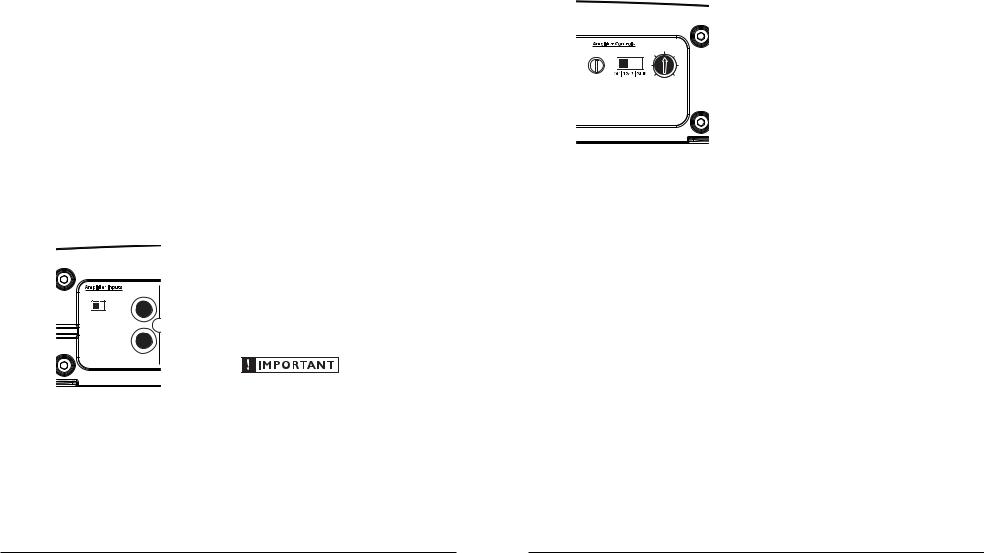
INPUT SECTION
The A1400’s input section allows you to send signal to the amplifier section through the use of two differential-balanced inputs, one for the left channel signal and one for the right channel signal. Connection is via RCA-type jacks.
CH 1 (Left)
Input Voltage
Low | High
CH 2 (Right)
You may run a stereo or a mono signal into the inputs of the amplifier. The amplifier’s input section automatically sums stereo signals to mono for the internal amplifier section. The amplifier will operate with only one input connection (left or right), but will require an increase in input sensitivity to overcome the loss of signal. If a mono input signal is to be run, we recommend that you use a “Y-adaptor” to split the mono signal into both inputs of the amplifier.
INPUT VOLTAGE RANGE:
A wide range of signal input voltages can be accommodated by the A1400’s input section (200mV – 8V). This wide range is split up into two sub-ranges, accessible via a switch located to the left of the Input Connectors.
The “Low” position on the “Input Voltage” switch selects an input sensitivity range between 200mV and 2V. This means that the “Input Sens.” rotary control will operate within that voltage window. If you are using an aftermarket source unit or an OEM interface processor with conventional preamp-level outputs, this is most likely the position that you will use.
The “High” position on the “Input Voltage” switch selects an input sensitivity range between 800mV and 8V. This is useful for certain highoutput preamp level signals as well as speakerlevel output from source units and
small amplifiers.
To use speaker-level sources, splice the speaker output wires of the source unit or small amplifier onto a pair of RCA plugs. No line output converter is needed in most cases.
The output of the amplifier will decrease for a given input voltage when the “Input Range” switch is placed in the “High” position.
Conversely, the output will be higher with the switch in the “Low” position. While this may sound counter-intuitive, it is consistent with the descriptions above.
AMPLIFIER CONTROLS
1)“Input Sens.”: Once the appropriate “Input Voltage” range has been selected, the control labeled “Input Sens.” located in the “Amplifier Controls” section can be used to match the source unit’s output voltage to the input
stage of the amplifier for maximum clean output. Rotating the control clockwise will result in higher sensitivity (louder for a given input voltage). Rotating the control counterclockwise will result in lower sensitivity (quieter for a given input voltage.)
|
|
Filter Freq. (Hz) |
||
Input Sens. |
LP Filter |
|
65 |
|
55 |
80 |
|||
|
|
|||
|
|
45 |
100 |
|
|
|
40 |
200 |
|
To properly set the amplifier for maximum clean output, please refer to Appendix A (page 12) in this manual. After using this procedure, you can then adjust any or all “Input Sens.” levels downward if this is required to achieve the desired system balance.
Do not increase any “Input Sens.” setting for any channel(s) of any amplifier in the system beyond the maximum level established during the procedure outlined in Appendix A (page 12). Doing so will result in audible distortion and possible speaker damage.
Filter Controls
Most speakers are not designed to reproduce the full range of frequencies audible by the human ear. For this reason, most speaker systems are comprised of multiple speakers, each dedicated to reproducing a specific frequency range. Filters are used to select which frequency range is sent to each section of a speaker system. The division of frequency ranges to different speakers can be done with passive filters (coils and/or capacitors between the amplifier outputs and the speakers), which are acceptable and commonly used for filtering between midrange speakers and tweeters. Filtering between subwoofer systems and satellite speaker systems is best done with active filters, which cut off frequency content at the input to the amplifier. Active filters are more stable than passive filters and do not introduce extraneous resistance, which can degrade subwoofer performance.
The active filter built into the A1400 can be used to eliminate potentially harmful and/or undesired frequencies from making their way through the amplifier sections to the speaker(s). This serves to improve tonal balance and to avoid distortion and possible speaker failure. Correct use of these filters can substantially increase the longevity and fidelity of your audio system.
The A1400 employs a sophisticated, variable, low-pass active filter for its internal channel. This feature is designed to attenuate frequencies above its filter frequency, so that the system’s subwoofers do not reproduce any audible midrange content.
2)Filter Operation: The low-pass filter in the A1400 is fully variable between 40 Hz and 200 Hz via the “Filter Freq.” control knob and features the ability to select between a moderate “12dB” per octave or a steep “24dB” per octave slope via the “Mode/Slope” switch.
Depending on the subwoofer system and the vehicle, different slopes may be required to produce a smooth transition to the midbass speakers in the system. Experiment to find the slope which best matches the acoustic requirements of your system.
6 |
JL AUDIO A1400 |
JL AUDIO A1400 |
7 |
 Loading...