

Jet MBS-1323EVS-H, MBS-1323EVS-H-4, 413412, 413415 Operating Instructions Manual

Operating Instructions and Parts Manual
Dual Mitering EVS Band Saw
Models MBS-1323EVS-H, MBS-1323EVS-H-4
JET
427 New Sanford Road
LaVergne, Tennessee 37086 Part No. M-413412
Ph.: 800-274-6848 Edition 5 04/2018
www.jettools.com Copyright © 2018 JET
1

1.0 IMPORTANT SAFETY
INSTRUCTIONS
WARNING – To reduce risk of injury:
1. Read and understand the entire owner's
manual before attempting assembly or
operation.
2. Read and understand the warnings posted on
the machine and in this manual. Failure to
comply with all of these warnings may cause
serious injury.
3. Replace the warning labels if they become
obscured or removed.
4. This band saw is designed and intended for use
by properly trained and experienced personnel
only. If you are not familiar with the proper and
safe operation of a band saw, do not use until
proper training and knowledge have been
obtained.
5. Do not use this band saw for other than its
intended use. If used for other purposes, JET
disclaims any real or implied warranty and holds
itself harmless from any injury that may result
from that use.
6. Always wear ANSI Z87.1 approved safety
glasses or face shield while using this band
saw. (Everyday eyeglasses only have impact
resistant lenses; they are not safety glasses.)
7. Before operating this machine, remove tie,
rings, watches and other jewelry, and roll
sleeves up past the elbows. Do not wear loose
clothing. Confine long hair. Non-slip footwear or
anti-skid floor strips are recommended. Do not
wear gloves.
8. Wear ear protectors (plugs or muffs) if noise
exceeds safe levels.
9. CALIFORNIA PROPOSITION 65 WARNING:
This product contains chemicals known to the
State of California to cause cancer, or birth
defects or other reproductive harm.
10. This product, when used for welding, cutting, or
working with metal, produces fumes, gases, or
dusts which contain chemicals known to the
State of California to cause birth defects and, in
some cases, cancer. (California Health and
Safety Code Section 25249.5 et seq.)
11. Make certain the switch is in the OFF position
before connecting the machine to the power
supply.
12. Make certain the machine is properly grounded.
13. Make all machine adjustments or maintenance
with the machine unplugged from the power
source.
14. Remove adjusting keys and wrenches. Form a
habit of checking to see that keys and adjusting
wrenches are removed from the machine
before turning it on.
15. Keep safety guards in place at all times when
the machine is in use. If removed for
maintenance purposes, use extreme caution
and replace the guards immediately after
completion of maintenance.
16. Check damaged parts. Before further use of the
machine, a guard or other part that is damaged
should be carefully checked to determine that it
will operate properly and perform its intended
function. Check for alignment of moving parts,
binding of moving parts, breakage of parts,
mounting and any other conditions that may
affect its operation. A guard or other part that is
damaged should be properly repaired or
replaced.
17. Provide for adequate space surrounding work
area and non-glare, overhead lighting.
18. Keep the floor around the machine clean and
free of scrap material, oil and grease.
19. Keep visitors a safe distance from the work
area. Keep children away.
20. Make your workshop child proof with padlocks,
master switches or by removing starter keys.
21. Give your work undivided attention. Looking
around, carrying on a conversation and “horseplay” are careless acts that can result in serious
injury.
22. Maintain a balanced stance at all times so that
you do not fall into the blade or other moving
parts. Do not overreach or use excessive force
to perform any machine operation.
23. Use the right tool at the correct speed and feed
rate. Do not force a tool or attachment to do a
job for which it was not designed. The right tool
will do the job better and more safely.
24. Use recommended accessories; improper
accessories may be hazardous.
25. Maintain tools with care. Keep saw blades
sharp and clean for the best and safest
performance. Follow instructions for lubricating
and changing accessories.
26. Maintain proper adjustment of blade tension,
blade guides and thrust bearings.
27. Turn off the machine before cleaning. Use a
brush to remove chips or debris — do not use
your hands.
2

28. Do not stand on the machine. Serious injury
could occur if the machine tips over.
29. Never leave the machine running unattended.
Turn the power off and do not leave the
machine until it comes to a complete stop.
30. Remove loose items and unnecessary work
pieces from the area before starting the
machine.
31. Never hand hold the material. Always use the
vise and clamp it securely.
32. Be sure that blade is not in contact with
workpiece when motor is started. Allow motor to
come up to speed before bringing blade into
contact with workpiece.
33. Avoid contact with coolant, especially guarding
your eyes.
35. Do not remove jammed pieces until blade has
stopped.
36. Don’t use in dangerous environment. Don’t use
power tools in damp or wet location, or expose
them to rain. Keep work area well lighted.
37. Use proper extension cord. Make sure your
extension cord is in good condition. When using
an extension cord, be sure to use one heavy
enough to carry the current your product will
draw. An undersized cord will cause a drop in
line voltage resulting in loss of power and
overheating. Table 2 (sect. 6.3) shows correct
size to use depending on cord length and
nameplate ampere rating. If in doubt, use the
next heavier gage. The smaller the gage
number, the heavier the cord.
34. Never reach around or over saw blade during
operation. Keep hands and fingers away from
blade area.
Familiarize yourself with the following safety notices used in this manual:
machine damage.
injury.
This means that if precautions are not heeded, it may result in minor injury and/or possible
This means that if precautions are not heeded, it may result in serious, or possibly even fatal,
3

2.0 Table of contents
Section Page
1.0 IMPORTANT SAFETY INSTRUCTIONS ....................................................................................................... 2
2.0 Table of contents ............................................................................................................................................ 4
3.0 About this manual .......................................................................................................................................... 5
4.0 Specifications ................................................................................................................................................. 6
5.0 Setup and assembly ....................................................................................................................................... 8
5.1 Shipping contents ....................................................................................................................................... 8
5.2 Unpacking and cleanup .............................................................................................................................. 8
5.3 Installation .................................................................................................................................................. 8
6.0 Electrical connections .................................................................................................................................... 8
6.1 GROUNDING INSTRUCTIONS ................................................................................................................. 8
6.2 Extension cords .......................................................................................................................................... 9
7.0 Adjustments ................................................................................................................................................... 9
7.1 Blade installation and removal ................................................................................................................... 9
7.2 Guide post adjustment ............................................................................................................................... 9
7.3 Blade guide adjustment .............................................................................................................................. 9
7.4 Blade tension and tracking ....................................................................................................................... 10
7.5 Belt tension ............................................................................................................................................... 11
7.6 Vise adjustment ........................................................................................................................................ 11
7.7 Bow swivel adjustment ............................................................................................................................. 12
7.8 Material stop ............................................................................................................................................. 12
7.9 Coolant flow .............................................................................................................................................. 12
8.0 Control panel ................................................................................................................................................ 12
9.0 Operation ..................................................................................................................................................... 13
9.1 Automatic shut-off .................................................................................................................................... 13
9.2 Auxiliary coolant hose .............................................................................................................................. 13
9.3 Prior to Operation ..................................................................................................................................... 13
9.4 General operating procedure ................................................................................................................... 13
9.5 Evaluating cutting efficiency ..................................................................................................................... 14
9.6 Blade selection ......................................................................................................................................... 14
9.7 Blade break-in procedures ....................................................................................................................... 14
10.0 User-maintenance ...................................................................................................................................... 15
10.1 General cleaning .................................................................................................................................... 15
10.2 Lubrication .............................................................................................................................................. 15
10.3 Belt replacement .................................................................................................................................... 15
10.4 Additional servicing ................................................................................................................................ 15
11.0 Optional accessory ..................................................................................................................................... 15
12.0 Troubleshooting MBS-1323EVS-H Band Saw ........................................................................................... 16
13.0 Replacement Parts ..................................................................................................................................... 17
13.1.1 MBS-1323EVS-H Bow Assembly – Exploded View ............................................................................ 18
13.1.2 MBS-1323EVS-H Bow Assembly – Parts List ..................................................................................... 19
13.2.1 MBS-1323EVS-H Base Assembly – Exploded View ........................................................................... 22
13.2.2 MBS-1323EVS-H Base Assembly – Parts List .................................................................................... 23
13.3.1 MBS-1323EVS-H Electrical Box Assembly – Exploded View ............................................................. 25
13.3.2 MBS-1323EVS-H Electrical Box Assembly – Parts List ...................................................................... 25
14.0 Electrical Connections for MBS-1323EVS-H ............................................................................................. 26
14.1 230V Only ............................................................................................................................................... 26
14.2 460V Only ............................................................................................................................................... 27
15.0 Warranty and service ................................................................................................................................. 28
4

3.0 About this manual
This manual is provided by JET, covering the safe operation and maintenance procedures for a JET Model MBS1323EVS-H Mitering Band Saw. This manual contains instructions on installation, safety precautions, general
operating procedures, maintenance instructions and parts breakdown. Your machine has been designed and
constructed to provide consistent, long-term operation if used in accordance with the instructions as set forth in
this document.
If there are questions or comments, please contact your local supplier or JET. JET c an also be reached at our
web site: www.jettools.com.
Retain this manual for future reference. If the machine transfers ownership, the manual should accompany it.
Read and understand the entire contents of this manual before attempting assembly or
operation! Failure to comply may cause serious injury!
Register your product using the mail-in card provided, or register online: http://www.jettools.c om/us/en/serviceand-support/warranty/registration/
5

4.0 Specifications
Table 1
Model number MBS-1323EVS-H MBS-1323EVS-H-4
Stock number – saw only
Motor and Electricals
Motor type Totally enclosed, fan cooled, induction
Horsepower 3 HP (2.25 kW)
Motor phase 3
Motor voltage 230 V 460 V
Cycle 60Hz
Listed FLA (full load amps) 8.2 4.1
Motor speed 1720 RPM
Power transfer Dual belt
Inverter B-type, 3HP 3PH 230V B-type, 3HP 3PH 460V
Power cord 2.0mm x 4C, 600V
Power plug n/a
Hydraulic pump 1/4HP, 230/460V, 3PH, 60Hz, 1.34/0.67A, 4P
Coolant pump 1/8HP, 220/440V, 3PH, 60Hz, 0.2/0.1A, 2850/3400min
Recommended circuit size 1 20 A
Sound emission without load 2 75 Db at 3 ft. from machine
Capacities
Maximum cutting capacity 12 x 23-1/2 in. (305 x 597 mm)
Bow swivel -45, +60 deg.
Maximum vise opening 600 mm
Blade speeds variable within 50 – 297 SFPM
Coolant tank capacity (approx.) 23L (5.2 gal.)
Gearbox oil capacity (approx.) 1 L (1 qt.)
90° 13 in. (330mm)
Round
+ 60° 11 in. (279mm)
- 45° 13 in. (330mm)
Cutting Capacity
Tubing or Solid
Square
90° 13 in. (330mm)
+ 60° 11 in. (279mm)
- 45° 13 in. (330mm)
90° 12 x 23-1/2 in. (305 x 597mm)
Rectangle
+ 60° 7 x 12 in. (178 x 305mm)
- 45° 8 x 16 in. (203 x 406.4 mm)
Main materials
Stand Welded steel plate
Bow Steel
Blade wheels Cast iron
Dimensions
Provided blade (4/6T) HSS, 1-1/4 x 0.043 x 172 in. (34 x 1.1 x 4365mm)
Table height from floor 700 mm
Table size 440 x 195 mm
Assembled dimensions (approx.) 88 x 55 x 51 in. (40 x 25 x 23 mm)
Shipping dimensions (approx.) 90 x 58 x 60 in. (41 x 26 x 27 mm)
Weights
Net (approx.) 1826 lbs (628.3 kg)
Shipping (approx.) 2090 lbs (948 kg)
413412 413415
6

1
subject to local and national electrical codes
2
The specified values are emission levels and are not necessarily to be seen as safe operating levels. As workplace
conditions vary, this information is intended to allow the user to make a better estimation of the hazards and risks
involved only.
L = length, W = width, H = height n/a = not applicable
The specifications in this manual were current at time of publication, but because of our policy of continuous
improvement, JET reserves the right to change specifications at any time and without prior notice, without
incurring obligations.
7

Read and understand all
assembly instructions before attempting
assembly. Failure to comply may cause serious
injury.
5.0 Setup and assembly
Disconnect band saw from
power during setup.
5.1 Shipping contents
5. Adjust leveling screws until machine is level in
both directions and tighten nuts against the
base flanges.
6. Install material stop into front hole in table, as
shown in Figure 7-9.
7. Fill coolant reservoir with 15L (4 gal.) of
appropriate coolant, by pouring it through the
filter screen atop the pan.
8. Install splash plate over lip of base and below
cutting area. This deflects coolant and chips
down into the base.
1 Band saw
1 Splash plate
1 Tool box containing:
6 Leveling pads
1 Set of open-end wrenches
1 Set of hex wrenches
1 Cross-point screwdriver
1 Adjustable wrench, 12 in.
6 Hex cap bolts, 1/2-20 x 2in.
6 Hex nuts, 1/2in.
5.2 Unpacking and cleanup
1. Finish uncrating saw and inspect for damage.
Should any have occurred, contact your local
distributor. Do not discard any packing material
until saw is set up and running properly.
2. Remove all bolts attaching machine to shipping
pallet. (The wood support beam can be
removed after machine has been connected to
power and the bow raised.)
3. Clean all rust protected surfaces with a cleanerdegreaser or kerosene to remove protective
coating. Do not use gasoline, paint thinner,
mineral spirits, etc. These may damage painted
surfaces.
4. Lubricate all slideways with SAE 10W oil.
5. Compare contents of shipping carton with the
contents list in this manual. Report shortages, if
any, to your distributor.
5.3 Installation
1. The band saw should be located on a solid and
level foundation, preferably concrete. Allow
room for bow swiveling, servicing and for
moving large stock around the machine.
2. Use lifting straps that are isolated from the band
saw’s finished surfaces and knobs, to move
machine to desired location. Position straps
under secure areas; do not strap bow or vise
assembly.
3. Install leveling bolts/nuts/pads, and the leveling
feet as desired, through the base flanges.
4. Place a level on the table surface and check
side-to-side and front-to-back.
6.0 Electrical connections
Electrical connections must be
made by a qualified electrician in compliance
with all relevant codes. This machine must be
properly grounded to help prevent electrical
shock and possible fatal injury.
The MBS-1323EVS-H Horizontal Band Saw is wired
for 3-phase, 230V; the MBS-1323EVS-H-4 is wired
for 3-phase 460V. The machine is not provided with
an electrical plug; you may either attach a proper
UL/CSA-listed plug, or “hardwire” the machine
directly to a service panel.
It is recommended that the band saw be connected
to a dedicated 20 amp circuit with circuit breaker or
time-delay fuse marked “D”. Local codes take
precedence over recommendations.
Before connecting to power source, be sure switch
is in off position.
6.1 GROUNDING INSTRUCTIONS
This tool must be grounded. In the event of a
malfunction or breakdown, grounding provides a
path of least resistance for electric current to reduce
the risk of electric shock. This tool is equipped with
an electric cord having an equipment-grounding
conductor. If a plug is used, it must be plugged into
a matching outlet that is properly installed and
grounded in accordance with all local codes and
ordinances.
Improper connection of the equipment-grounding
conductor can result in a risk of electric shock. The
conductor with insulation having an outer surface
that is green with or without yellow stripes is the
equipment-grounding conductor. If repair or
replacement of the electric cord or plug is
necessary, do not connect the equipment-grounding
conductor to a live terminal.
Check with a qualified
electrician or service personnel if the grounding
instructions are not completely understood, or if
in doubt as to whether the tool is properly
grounded. Failure to comply may cause ser ious
or fatal injury.
8
If hardwired:
Permanently connected tools: This tool should be
connected to a grounded metal permanent wiring
system; or to a system having an equipmentgrounding conductor. Make sure a disconnect is
available for the operator. During hard-wiring of the
machine, make sure the fuses have been removed
or the breakers have been tripped in the circuit to
which the drill press will be connected. ALWAYS
FOLLOW PROPER LOCK-OUT/TAG-OUT PROCEDURES.
6.2 Extension cords
The use of extension cords is discouraged; try to
position equipment within reach of the power
source. If an extension cord becomes necessary, be
sure it is heavy enough to carry the current your
product will draw. An undersized cord will cause a
drop in line voltage resulting in loss of power and
overheating.
Table 2 shows recommended size to use depending
on cord length and nameplate ampere rating. If in
doubt, use the next heavier gauge. The smaller the
gauge number, the heavier the cord.
Ampere
Rating
More
Than
Not
More
Than
0 6 18 16 16 14
6 10 18 16 14 12
10 12 16 16 14 12
12 16 14 12
Extension Cord Recommendations
Volts
240 50 100 200 300
AWG
Total length of
cord in feet
Not
Recommended
Table 2
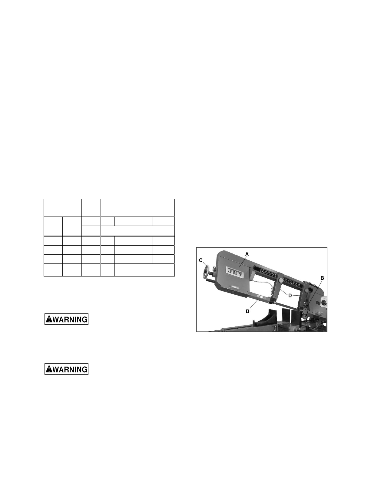
3. Open both wheel covers (A, Figure 7-1) and
clean out any swarf from wheel areas.
4. Remove red blade guards (B).
5. Back off the blade guides by loosening knob (H,
Figure 7-2). Back off the wire chip brush.
6. Release blade tension by turning blade tension
handwheel (C) counter-clockwise.
7. Remove blade from both wheels and out of
each blade guide.
8. Make sure teeth of new blade are pointing in
direction of travel. If necessary, turn blade
inside out.
9. Position new blade around wheels and through
upper slot. Slide it into blade guide bearings
with back edge of blade contacting backup
bearing. (see Figure 7-2). For further guide
bearing adjustment, see sect. 7.3
10. Lightly increase tension (C) and position blade
so it rests against shoulder of both wheels.
11. When blade is properly positioned, place full
tension upon it (see sect. 7.4.1).
12. Reinstall blade guards (B).
13. Adjust chip brush up against blade teeth.
14. Jog the start/stop buttons to ensure blade is
tracking properly. If tracking adjustment is
needed, see sect. 7.4.2.
15. Close wheel covers.
7.0 Adjustments
Disconnect machine from
power source before making adjustments,
unless indicated otherwise.
7.1 Blade installation and removal
Refer to Figure 7-1.
Always wear leather gloves
when handling blades to avoid injury.
A blade (1-1/4 in. W x 172 in. L) is pre-installed and
tensioned on saw. To replace blade:
1. Raise bow about 15-degrees and keep it in
raised position by turning feed rate control knob
clockwise all the way (see sect. 8.0).
2. Disconnect machine from power source.
Figure 7-1: blade changing
7.2 Guide post adjustment
The blade guide posts (D, Figure 7-1) must be set
to just clear the workpiece, but should not interfere
with workpiece or other saw components during
bow’s descent.
Loosen knobs and slide posts into position. Always
tighten knobs before operating machine.
7.3 Blade guide adjustment
The bearing and carbide guides come pre-adjusted
from the factory for the installed blade. If adjustment
is needed, or if a blade is replaced, follow the below
steps for left and right guides.
9
 Loading...