

Jet LF-20 Operating Instructions And Parts Manual

This .pdf document is bookmarked
Operating Instructions and Parts Manual
20-Ga. Pittsburgh Lockformer
Model LF-20
JET
427 New Sanford Road
LaVergne, Tennessee 37086 Part No. M-756090
Ph.: 800-274-6848 Edition 2 05/2019
www.jettools.com Copyright © 2016 JET

1.0 IMPORTANT SAFETY
INSTRUCTIONS
WARNING – To reduce risk of injury:
1. Read and understand the entire owner's
manual before attempting assembly or
operation.
2. Read and understand the warnings posted on
the machine and in this manual. Failure to
comply with all of these warnings may cause
serious injury.
3. Replace warning labels if they become
obscured or removed.
4. This lockformer is designed and intended for
use by properly trained and experienced
personnel only. If you are not familiar with the
proper and safe operation of a lockformer, do
not use until proper training and knowledge
have been obtained.
5. Do not use this machine for other than its
intended use. If used for other purposes, JET
disclaims any real or implied warranty and holds
itself harmless from any injury that may result
from that use.
6. Always wear ANSI Z87.1 approved safety
glasses or face shield while using this machine.
(Everyday eyeglasses only have impact
resistant lenses; they are not safety glasses.)
7. Before operating this machine, remove tie,
rings, watches and other jewelry, and roll
sleeves up past the elbows. Do not wear loose
clothing. Confine long hair. Non-slip footwear or
anti-skid floor strips are recommended. Do not
wear gloves.
8. Wear hearing protection (plugs or muffs) if
noise exceeds safe levels.
9. Do not operate this machine while tired or under
the influence of drugs, alcohol or any
medication.
10. Make certain switch is in OFF position before
connecting the machine to the power supply.
11. Make certain the machine is properly grounded.
12. Make all machine adjustments or maintenance
with the machine unplugged from the power
source.
13. Remove adjusting keys and wrenches. Form a
habit of checking to see that keys and adjusting
wrenches are removed from the machine
before turning it on.
14. Keep safety guards in place at all times when
the machine is in use. If removed for
maintenance purposes, use extreme caution
and replace the guards immediately after
completion of maintenance.
15. Check damaged parts. Before further use of the
machine, a guard or other part that is damaged
should be carefully checked to determine that it
will operate properly and perform its intended
function. Check for alignment of moving parts,
binding of moving parts, breakage of parts,
mounting and any other conditions that may
affect its operation. A guard or other part that is
damaged should be properly repaired or
replaced.
16. Provide for adequate space surrounding work
area and non-glare, overhead lighting.
17. Keep the floor around the machine clean and
free of scrap material, oil and grease.
18. Keep visitors a safe distance from the work
area. Keep children away.
19. Make your workshop child proof with padlocks,
master switches or by removing starter keys.
20. Give your work undivided attention. Looking
around, carrying on a conversation and “horseplay” are careless acts that can result in serious
injury.
21. Maintain a balanced stance at all times so that
you do not fall onto moving parts. Do not
overreach or use excessive force to perform
any machine operation.
22. Use the right tool at the correct speed and feed
rate. Do not force a tool or attachment to do a
job for which it was not designed. The right tool
will do the job better and more safely.
23. Use recommended accessories; improper
accessories may be hazardous.
24. Maintain tools with care. Follow instructions for
lubricating and changing accessories.
25. Turn off the machine before cleaning. Use a
brush to remove chips or debris — do not use
bare hands.
26. Do not stand on the machine. Serious injury
could occur if the machine tips over.
27. Never leave the machine running unattended.
Turn the power off and do not leave the
machine until it comes to a complete stop.
28. Remove loose items and unnecessary work
pieces from the area before starting the
machine.
29. Disconnect machine from power source
(unplug) before changing out roll sets.
30. Top covers must be properly installed before
feeding workpiece.
2

31. Don’t use in dangerous environment. Don’t use
power tools in damp or wet location, or expose
them to rain. Keep work area well lighted.
32. Use proper extension cord. Make sure your
extension cord is in good condition. When using
an extension cord, be sure to use one heavy
enough to carry the current your product will
draw. An undersized cord will cause a drop in
line voltage resulting in loss of power and
overheating. Table 1 (sect. 6.2) shows correct
size to use depending on cord length and
nameplate ampere rating. If in doubt, use the
next heavier gage. The smaller the gage
number, the heavier the cord.
WARNING: This product can expose you to
chemicals including lead which is known to the
State of California to cause cancer and birth
defects or other reproductive harm. For more
information go to http://www.p65warnings.ca.
gov.
Familiarize yourself with the following safety notices used in this manual:
WARNING: Some dust, fumes and gases
created by power sanding, sawing, grinding,
drilling, welding and other construction activities
contain chemicals known to the State of
California to cause cancer and birth defects or
other reproductive harm. Some examples of
these chemicals are:
lead from lead based paint
crystalline silica from bricks, cement and
other masonry products
arsenic and chromium from chemically
treated lumber
Your risk of exposure varies, depending on how
often you do this type of work. To reduce your
exposure to these chemicals, work in a wellventilated area and work with approved safety
equipment, such as dust masks that are
specifically designed to filter out microscopic
particles. For more information go to
http://www.p65warnings.ca.gov/ and http://www.
p65warnings.ca.gov/wood.
This means that if precautions are not heeded, it may result in minor injury and/or possible
machine damage.
This means that if precautions are not heeded, it may result in serious, or possibly even fatal,
injury.
2.0 About this manual
This manual is provided by JET, covering the safe operation and maintenance procedures for a JET Model LF20 Lockformer. This manual contains instructions on installation, safety precautions, general operating
procedures, maintenance instructions and parts breakdown. Your machine has been designed and constructed
to provide consistent, long-term operation if used in accordance with the instructions as set forth in this document.
If there are questions or comments, please contact your local supplier or JET. JET can also be reached at our
web site: www.jettools.com.
Retain this manual for future reference. If the machine transfers ownership, the manual should accompany it.
Read and understand the entire contents of this manual before attempting assembly or
operation! Failure to comply may cause serious injury!
Register your product with the provided mail-in card or register online -
http://www.jettools.com/us/en/service-and-support/warranty/registration/
3

3.0 Table of contents
Section Page
1.0 IMPORTANT SAFETY INSTRUCTIONS ....................................................................................................... 2
2.0 About this manual .......................................................................................................................................... 3
3.0 Table of contents ............................................................................................................................................ 4
4.0 Specifications ................................................................................................................................................. 5
5.0 Setup and assembly ....................................................................................................................................... 6
5.1 Shipping contents ....................................................................................................................................... 6
6.0 Electrical connections .................................................................................................................................... 6
6.1 GROUNDING INSTRUCTIONS ................................................................................................................. 6
6.2 Extension cords .......................................................................................................................................... 7
7.0 Operation ....................................................................................................................................................... 7
7.1 Pittsburgh Lock Seam procedure ............................................................................................................... 7
7.2 Double Seam procedure ............................................................................................................................ 8
7.3 Drive Cleat procedure ................................................................................................................................ 8
8.0 Adjustments ................................................................................................................................................... 9
8.1 Hold-downs ................................................................................................................................................ 9
9.0 User-maintenance .......................................................................................................................................... 9
9.1 Cleaning and lubrication ............................................................................................................................. 9
9.2 Additional servicing .................................................................................................................................... 9
10.0 Replacement Parts ....................................................................................................................................... 9
10.1.1 LF-20 Lockformer – Exploded View .................................................................................................... 10
10.1.2 LF-20 Lockformer – Parts List ............................................................................................................. 11
10.2.1 LF-20 Upper Bracket – Exploded View ............................................................................................... 12
10.2.2 LF-20 Upper Bracket – Parts List ........................................................................................................ 13
10.3.1 LF-20 Lower Bracket – Exploded View ............................................................................................... 14
10.3.2 LF-20 Lower Bracket – Parts List ........................................................................................................ 15
10.4.1 LF-20 Optional Rollers – Exploded View ............................................................................................. 16
10.4.2 LF-20 Optional Rollers – Parts List ..................................................................................................... 16
11.0 Electrical Connections for LF-20 ................................................................................................................ 17
12.0 Warranty and service ................................................................................................................................. 18
The specifications in this manual were current at time of publication, but because of our policy of continuous
improvement, JET reserves the right to change specifications at any time and without prior notice, without
incurring obligations.
4
4.0 Specifications
Model number ............................................................................................................................................... LF-20
Stock number .............................................................................................................................................. 756090
Motor and electricals:
Motor type ............................................................................................................................. TEFC, capacitor start
Horsepower .............................................................................................................................................. 1.5HP
Phase ........................................................................................................................................................ single
Voltage ...................................................................................................................................................... 115 V
Cycle .......................................................................................................................................................... 60Hz
Listed FLA (full load amps) ......................................................................................................................... 14 A
Running amps (no load) ............................................................................................................................. 7.1 A
Starting amps .............................................................................................................................................. 51 A
Start capacitor .......................................................................................................................... 200MF 125VAC
Run capacitor .............................................................................................................................. 40F 250VAC
Power transfer ........................................................................................................................................... V-belt
On/off switch .................................................................................................... mushroom style with safety key
Power cord ........................................................................................................ SJT 3/14AWG; 6 ft. (1830 mm)
Power plug installed ...................................................................................................................... NEMA 5-15P
Recommended circuit and fuse/breaker size
Capacities:
Pittsburgh lock dimensions ........................................ Approx. 25mm (1-in.) of material, 0.5-1.0mm (20-26ga.)
8mm (5/16 in.) width of hammer-over edge, adjustable up to 9.5mm (3/8 in.)
Speed ..................................................................................................................................... 7.62m (25 ft.)/min
Minimum length of workpiece ....................................................................................................... 7 in. (178mm)
Main materials:
Cabinet ....................................................................................................................................................... steel
Rolls ................................................................................................................................... hardened alloy steel
Guide fences .............................................................................................................................. hardened steel
Shafts ................................................................................... hardened and ground steel, with needle bearings
Dimensions:
Height table from floor ......................................................................................................... 819 mm (32-1/4 in.)
Overall dimensions (LxWxH) ..................................................... 914 x 419 x 927 mm (36 x 16-1/2 x 36-1/2 in.)
Shipping dimensions (LxWxH) .......................................... 1075 x 510 x 1075 mm (42-5/16 x 20 x 42-5/16 in.)
Weights:
Net .......................................................................................................................................... 266 lb. (120.6 kg)
Shipping ................................................................................................................................. 341 lb. (154.6 kg)
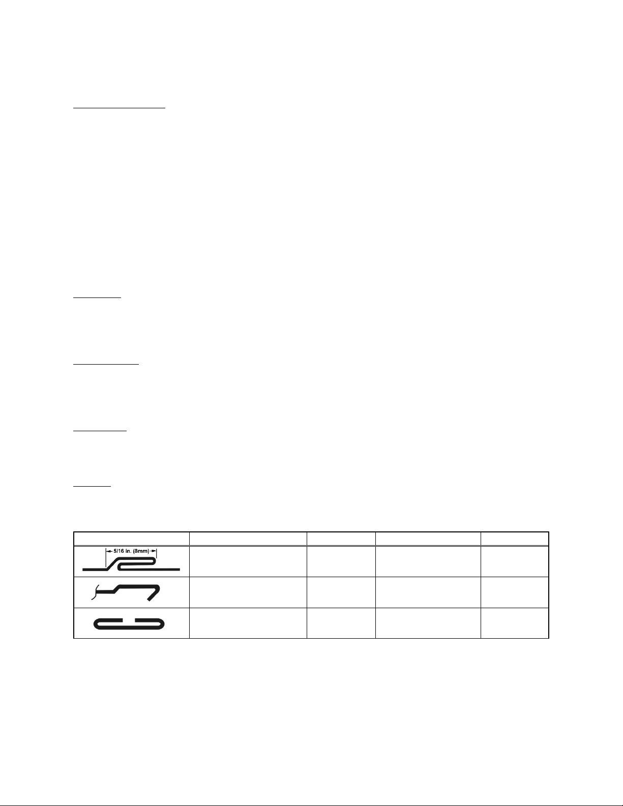
Type Roll set Capacity Approx. mat’l used Size
Pittsburgh lock seam
(standard, pre-mounted)
Double seam (DSS)
OPTIONAL
Drive cleat (DCS)
OPTIONAL
1
Subject to local and national electrical codes.
2
Optional Double Seam and Drive Cleat roll sets are available from JET. See sect. 10.4.1.
1
............................................................................................. 15A
0.5 - 1.0 mm
20 to 26 ga
2
2
0.5 - 1.0 mm
20 to 26 ga.
0.5 – 1.0 mm
20 to 26 ga.
25mm (1”)
25.4mm (1”)
54mm (2-1/8”)
8 mm
5/16” width
10 mm
3/8” seam
28.5 mm
1-1/8” width
5

Read and understand the entire
contents of this manual before attempting setup or operation! Failure to comply may cause
serious injury.
5.0 Setup and assembly
Remove all crating and check for shipping damage.
Report any damage immediately to your distributor
and shipping agent. Do not discard any shipping
material until the Lockformer is assembled and
running properly.
Compare contents with the following list to make
sure all parts are intact. Any missing parts should be
reported to your distributor. Read this instruction
manual thoroughly for operation, maintenance and
safety instructions.
Remove fasteners holding machine to pallet, and
use forklift or hoist with straps to move lockformer to
position. Location should be well-lighted, with a
sturdy, level floor. It is recommended that the
machine be secured to the floor with lag screws or
other means for stability.
5.1 Shipping contents
1 Lockformer
2 Wrenches, 23/26 and 12/14mm
2 Hex wrenches, 4mm and 6mm
1 Formed sample plate
10 Double head round keys
1 Operating instructions and parts manual
1 Product registration card
6.0 Electrical connections
All electrical connections must
be done by a qualified electrician in compliance
with all local codes and ordinances. Failure to
comply may result in serious injury.
The LF-20 Lockformer is rated at 115-volt power
only, and is supplied with a plug designed for use on
a circuit with a grounded outlet that looks like the
one pictured in Figure 6-1.
Before connecting to power source, be sure switch
is in off position.
It is recommended that the Lockformer be
connected to a dedicated 15 amp circuit with circuit
breaker or fuse. If connected to a circuit protected
by fuses, use time delay fuse marked “D”. Local
codes take precedence over recommendations.
6.1 GROUNDING INSTRUCTIONS
This machine must be grounded. In the event of a
malfunction or breakdown, grounding provides a
path of least resistance for electric current to reduce
the risk of electric shock. This tool is equipped with
an electric cord having an equipment-grounding
conductor and a grounding plug. The plug must be
plugged into a matching outlet that is properly
installed and grounded in accordance with all local
codes and ordinances.
Do not modify the plug provided - if it will not fit the
outlet, have the proper outlet installed by a qualified
electrician.
Improper connection of the equipment-grounding
conductor can result in a risk of electric shock. The
conductor with insulation having an outer surface
that is green with or without yellow stripes is the
equipment-grounding conductor. If repair or
replacement of the electric cord or plug is
necessary, do not connect the equipment-grounding
conductor to a live terminal.
Check with a qualified
electrician or service personnel if the grounding
instructions are not completely understood, or if
in doubt as to whether the tool is properly
grounded. Failure to comply may cause serious
or fatal injury.
Use only 3-wire extension cords that have 3-prong
grounding plugs and 3-pole receptacles that accept
the tool's plug.
Repair or replace damaged or worn cord
immediately.
This machine is for use on a nominal 120-V circuit,
and has a grounded plug that looks like the plug
illustrated in sketch A in Figure 6-1. A temporary
adaptor that looks like the adaptor illustrated in
sketch B may be used to connect this plug to a 2pole receptacle as shown in sketch B if a properly
grounded outlet is not available. The temporary
adaptor should be used only until a properly
grounded outlet (sketch A) can be installed by a
qualified electrician. The green colored rigid ear,
lug, or the like extending from the adaptor must be
connected to a permanent ground such as a
properly grounded outlet box cover. Whenever the
adaptor is used, it must be held in place by a metal
screw.
In Canada, the use of a temporary adaptor is not
permitted by the Canadian Electrical Code, C22.1.
Figure 6-1
6
 Loading...