


J-A5818
Table of contents
 Loading...
Operating Instructions and Parts Manual
15-inch Variable Speed Drill Press
Models: J-A3816, J-A5816, J- A5818
Model J-A5816 Model J-A3816
JET
427 New Sanford Road
LaVergne, Tennessee 37086 Part No. M-354500
Ph.: 800-274-6848 Revision F 01/2016
www.jettools.com Copyright © 2016 JET
This .pdf document is bookmarked

2
Warranty and Service
JET warrants every product it sells against manufacturers’ defects. If one of our tools needs service or repair, please contact
Technical Service by calling 1-800-274-6846, 8AM to 5PM CST, Monday through Friday.
Warranty Period
The general warranty lasts for the time period specified in the literature included with your product or on the official JET
branded website.
• JET products carry a limited warranty which varies in duration based upon the product. (See chart below)
• Accessories carry a limited warranty of one year from the date of receipt.
• Consumable items are defined as expendable parts or accessories expected to become inoperable within a
reasonable amount of use and are covered by a 90 day limited warranty against manufacturer’s defects.
Who is Covered
This warranty covers only the initial purchaser of the product from the date of delivery.
What is Co vered
This warranty covers any defects in workmanship or materials subject to the limitations stated below. This warranty does not
cover failures due directly or indirectly to misuse, abuse, negligence or accidents, normal wear-and-tear, improper repair,
alterations or lack of maintenance. JET woodworking machinery is designed to be used with Wood. Use of these machines in
the proc essing of metal , pl asti cs, or other materials outside rec ommended gui deli nes ma y void the warranty. The except ions
are acrylics and other natural items that are made specifically for wood turning.
Warranty Limitations
Woodworking products with a Five Year Warranty that are used for commercial or industrial purposes default to a Two Year
Warranty. Please contact Technical Service at 1-800-274-6846 for further clarification.
How to Get Technical Support
Please contact Technical Service by calling 1-800-274-6846. Please note that you will be asked to provide proof of ini tial
purchase when calling. If a product requir es further inspection, the Technical Service representative will expla in and assist
with any additional action needed. JET has Authorized Service Centers located throughout the United States. For the name of
an Authorized Service Center in your area call 1-800-274-6846 or use the Service Center Locator on the JET website.
More Informa t io n
JET is constantly adding new products. For complete, up-to-date product information, check with your local distributor or visit
the JET w ebsite.
How State Law Appli es
This warranty gives you specific legal rights, subject to applicable state law.
Limitations on This Warranty
JET LIMITS ALL IMPLIED WARRANTIES TO THE PERIOD OF THE LIMITED WARRANTY FOR EACH PRODUCT.
EXCEPT AS STATED HEREIN, ANY IMPLIED WARRANTIES OF MERCHANTABILITY AND FITNESS FOR A PARTICULAR
PURPOSE ARE EXCLUDED. SOME STATES DO NOT ALLOW LIMITATIONS ON HOW LONG AN IMPLIED WARRANTY
LASTS, SO THE ABOVE LIMITATION MAY NOT APPLY TO YOU.
JET SHALL IN NO EVENT BE LIABLE FOR DEATH, INJURIES TO PERSONS OR PROPERTY, OR FOR INCIDENTAL,
CONTINGENT, SPECIAL, OR CONSEQUENTIAL DAMAGES ARISING FROM THE USE OF OUR PRODUCTS. SOME
STATES DO NOT ALLOW THE EXCLUSION OR LIMITATION OF INCIDENTAL OR CONSEQUENTIAL DAMAGES, SO THE
ABOVE LIMITATION OR EXCLUSION MAY NOT APPLY TO YOU.
JET sells through distributors only. The specifications listed in JET printed materials and on official JET website are given as
general information and are not binding. JET reserves the right to effect at any time, without prior notice, those alterations to
parts, fittings, and accessory equipment which they may deem necessary for any reason whatsoever. JET
®
branded products
are not sold in Canada by JPW Industries, Inc.
Product Listing with Warranty Period
90 Days – Parts; Consumable items
1 Year – Motors; Machine Accessories
2 Year – Metalworking Machinery; Electric Hoists, Electric Hoist Accessories; Woodworking Machinery used
for industrial or commercial purposes
5 Year – Woodworking Machinery
Limited Lifetime – JET Parallel clamps; VOLT Series Electric Hoists; Manual Hoists; Manual Hoist
Accessories; Shop Tools; Warehouse & Dock products; Hand Tools; Air Tools
NOTE: JET is a division of JPW Industries, Inc. References in this document to JET also apply to JPW Industries, Inc., or any
of its successors in interest to the JET brand .

3
Table of Contents
Warranty and Servic e .......................................................................................................................................... 2
Table of Contents ................................................................................................................................................ 3
Warnings ............................................................................................................................................................. 4
Safety Instruction s for Dril l Pr e sses .................................................................................................................. 6
ON/OFF Switch Padlock ................................................................................................................................... 6
Specifica tio ns ...................................................................................................................................................... 7
Introduction .......................................................................................................................................................... 8
Set-up and Assembl y ........................................................................................................................................... 8
Securing the Base ............................................................................................................................................ 8
Assembly ......................................................................................................................................................... 8
Cleaning .............................................................................................................................................................. 9
Electri c al Connec tion ........................................................................................................................................... 9
Operating Contr ols ............................................................................................................................................... 9
ON/OFF Switch ................................................................................................................................................ 9
Speed Control Handwheel ................................................................................................................................ 9
Depth Stop ..................................................................................................................................................... 10
Operating P re c a u tions .................................................................................................................................... 10
Drilling Recommendations ................................................................................................................................. 10
Maintenance ...................................................................................................................................................... 11
Replacement of Drive Belt .............................................................................................................................. 11
Replacement of Motor .................................................................................................................................... 11
Lubrication ......................................................................................................................................................... 11
Adjustments ....................................................................................................................................................... 11
Table Adjustment ........................................................................................................................................... 11
Wiring Diagrams ................................................................................................................................................ 12
Electrical ............................................................................................................................................................ 1 3
115 Volt Operati on ......................................................................................................................................... 13
230 Volt Operati on ......................................................................................................................................... 13
Permanentl y Connect ed Tools ........................................................................................................................ 13
Grounding Inst r uc tions ................................................................................................................................... 14
Extension Cords ............................................................................................................................................. 14
Troubleshooting ................................................................................................................................................. 15
Parts .................................................................................................................................................................. 15
Exploded View — Head Model s J-A 5816 and J - A 5818 ................................................................................... 16
Parts List - Head Models J-A 5816 and J - A 5818 .............................................................................................. 17
Exploded View — Head Model J-A3816 ......................................................................................................... 19
Parts List - Head Model J -A3816 .................................................................................................................... 2 0
Exploded View – Base Floor M odels J-A 3816, J-A5816 and J-A5818 ............................................................. 22
Parts List – Base Floor M odels J-A3816, J-A5816 and J-A5818 ...................................................................... 23
Exploded View – Safet y Shi eld A ssembly, Models J-A3816, J-A5816 and J- A 5818 ........................................ 24
Parts List – Safety Shield Assembly (All Models) ............................................................................................ 24
The specifi cati ons in thi s m anual ar e given as general inf ormati on and are not bi nding. JET reserves the ri ght t o
effect, at any time and without prior notice, changes or alterations to parts, fittings, and accessory equipment
deemed necessary f or any reason whatsoever.

4
Warnings
1. Read and understand the ent ire owner's manual bef or e attempting assembly or operation.
2. Read and understand warni ngs posted on the m ac hine and in t hi s manual. F ailur e to comply wit h all of these
warnings may cause seriou s i njury.
3. Replace warning l abels if they become obscured or remov ed.
4. This drill press is designed and intended f or use by proper ly trained and ex perienced personnel onl y. If you
are not familiar with the proper and safe operation of a drill press, do not use until proper training and
knowledge have been obtained.
5. Do not use this drill press for other than its intended use. If used for other purpose s, JET discl aim s any real or
implied warrant y and holds itself harmless from any injury t hat may result from that use.
6. Keep guards in place and in working or der when the m ac hine is in use. If removed for maintenanc e pur pose s,
use extreme caution and replace the guards immediately.
7. Remove adjust ing keys and wrenches. Form habit of checki ng to see that keys and adjusti ng wrenches are
removed from tool before turning it on.
8. Keep work area clean. Cluttered areas and benches invite accidents.
9. Do not use in dangerous environment. Don't use power tools in damp or wet locati ons, or expose them to
rain. Keep work area well lighted.
10. K eep c hildren away. All vi sitor s should be k ept safe distance from work area.
11. M ak e worksh op k id proof with padlocks, master switches, or by rem ov ing starter keys.
12. Don' t force tool. It will do the job better and safer at the rate for whic h it was designed.
13. Use the right tool. Don’t force a tool or attachment to do a job f or whic h it was not designed. The right tool will
do the job better and m or e safely at t he rate for which it was designed.
14. Use proper ext ension cord. Mak e sure your ext ension cord is in good condition. When using an ex tension
cord, be sure to use one heavy enough to c arry the current your product will draw. An undersiz ed cord will
cause a drop in li ne volt age result ing in l oss of power and overheat i ng. Tabl e 1 shows the correct size t o use
depending on cord l ength and nam eplate am pere rati ng. If i n doubt, use t he next heav ier gage. The sm aller
the gage number, t he heav ier the cor d.
15. Wear proper appar el. Do not wear loose clot hing, gloves, neckties, rings, bracel ets, or other jewelry which
may get caught i n moving part s. Nonslip foot wear is recomm ended. Wear prot ective hair cov ering to cont ain
long hair.
16. Alwa ys use safety glasses. A lso use face or dust mask if cutting operation is dusty. Everyday eyeglasses only
have impact resistant lenses, they are NOT safety glasses.
17. Secure work. Make sure t he work pi ece i s securely attached or c l amped to t he table. Never use your hand to
hold the work piec e.
18. Don' t overreach. K eep pr oper footing and balance at all times.
19. Maint ain tools with care. Keep tool s sharp and clean for best and safest perf ormance. Foll ow instructi ons for
lubricating and changing accessories.
20. Disconnect tools before servicing; when changing acc es sories, such as blades, bits, cutters, and the like.
21. Reduc e the risk of unint entional starting. Mak e sure switch is i n off position before plugging in.
22. Use recommended accessories. Consult the owner's manual for recommended accessories. The use of
improper acc essories may cause risk of injury to per sons.
23. Never stand on tool. Serious injury could occur if the tool is tipped or if the cutting tool is unintentionally
contacted.

5
24. Check f or damaged parts. Before further use of the tool , a guard or other part that is dam aged should be
carefully checked to determine that it will operate properly and perform its intended function - check for
alignment of movi ng parts, binding of mov ing parts, breakage of parts, mounting, and any other conditi ons
that may affect its operation.
25. A guar d or other part that is damaged should be properly repaired or r eplac ed.
26. Do not leave tool runni ng unatt ended. Turn power off. Don't leav e tool unt il it comes to a complete stop.
27. Some dust created by power sanding, sawing, grinding, drilling and other construction activities contain
chemicals known to cause cancer, birth defects or other reproductive harm. Some examples of these
chemicals are:
• Lead from lead based paint.
• Crystalli ne sil ic a from bricks, cement and other m asonry pr oduc ts.
• Arsenic and chromium from chemically treated lum ber .
Your risk of ex posure varies, depending on how of ten you do this type of work. To reduce your exposure to
these chemical s: work in a well-ventil ated area and work with approved safety equipment, such as face or
dust masks that are specifically designed to filter out microscopic particles.
28. M ak e c ertain the switch is in the OFF position before connecting the machine to the power supply.
29. M ak e c ertain the machine is properly grounded.
30. Give your work undivided att ention. Looking ar ound, carrying on a conversation and “horse-play” are careless
acts that can resul t in seri ous i njury.
31. The operator should not wear gl ov es when operating the machine.
32. All doors should be closed, all panels replaced and other safety guards should be in place prior to the
machine being st ar ted or operated.
33. Be sure the drill bit is not i n contact with the work piece when the motor is started. The motor should be
started and up to full speed before bringing the drill bit into contact with the work piece.
34. K eep y our hands a way from the drilling ar ea.
35. T he drill pr ess must be stopped and t he electri cal supply must be c ut off before any drill bit replacem ent or
machine adjust ment is done, or bef ore any att empt i s made to change t he driv e belt s or before any per iodic
service or maint enanc e is performed on the drill press.
36. Remove loose item s and unnecessary work pieces from the area before starting the machine.
37. The work piece must be securel y cl am ped before the drill bit comes in contact with the work piece.
38. T he drill press must be stopp ed and the electr ical supply cut off or machine unplugged befor e reaching into
the drilli ng area.
39. Wear eye protection.
40. Do not remove jammed pieces until motor has stopped.
41. Hold workpiece firmly against table.
6
Safety Instructions for Drill Presses
1. All work shal l be secured u sing eit her clam ps or
a vise to the drill pr ess table. It is unsafe to use
your hands to hold any workpi ec e being drilled.
2. Drill press head and table shall be securely
locked to the column before operating the drill
press. This must always be checked prior to
starting t he m achi ne.
3. Always use the correct tooling. Tooling shall
always be maintained and properly sharpened.
All tooli ng must be run at the pr oper speeds and
feeds as they apply to the job. Use only
recommended accessories and follow those
manufacturer’s instructions pertaining to them.
Tooling shall be not be forced in to any
workpiece but fed according to the proper
specifications. Failure to follow these
instructions will not only ruin the tooling as well
as the machine, but can c ause serious i njury.
4. Never brush away any chips while the machi ne
is in operation. All clean up should be done
when the machine is stopped.
5. Keep hands in sight. Do not put hand s or fi nger s
around, on, or below any rotating cutting tools.
Leather safety gloves should be used when
handling any sharp obj ects or cut ti ng t ools. See
Figure A.
6. Always wear protective eye wear when
operating, servicing or adjusting machinery.
Eyewear shall be impact resistant, protective
safety glasses with side shi elds complyi ng with
ANSI Z87.1 specifi cations. Use of the eye wear
which does not comply with ANSI Z87.1
specifications could result i n severe injury from
breakage of eye prot ec tion. See Figure B.
7. When drilling in material which causes dust, a
dust mask shall be worn.
8. Avoid contact with coolant, especially guarding
the eyes.
9. Non-slip footwear and safety shoes are
recommended. See Figure C.
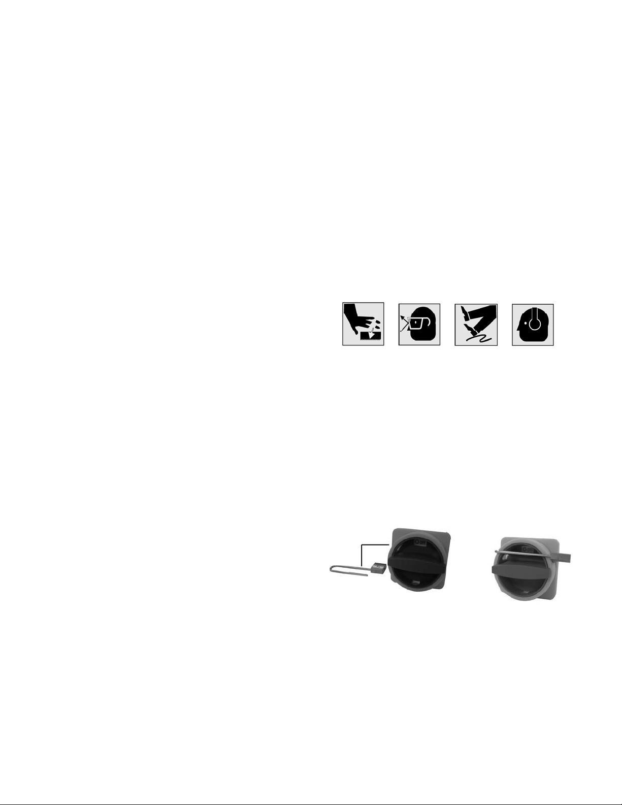
10. Wear ear protectors (plugs or muffs) during
extended periods of operation. See Figure D.
A B C D
ON/OFF Switch Padlock
For Model Numbers A5816 and A5818
To avoid accidental starting by young children or
others not qualified to use the tool, the use of a
padlock is required.
1. Open the padlock (Fig E).
2. Insert the thr ough hole in the switch cover.
3. Close the padlock (Fig F).
4. Place the key in a safe place.
Figure E Figure F

7
Specifications
The JET 15-Inch Vari-Speed Drill Presses, Models
J-A3816, J-A5816, and J-A5818 provide drilling
speeds from 400 to 5,000 rpm. Simple handwheel
adjustment sets the speeds with an LED speed
display on the faceplate of the machine.
JET's 15-inc h vari-speed drill press provides a solid
base for drilling and offers a wide range of spindle
speeds. The large quill provides greater accuracy.
The large worktabl e prov i des the operat or wit h room
to work and ample support for the workpiece. The
drill press has a 3-inch diameter column for head
and table support. The 15-Inch Vari-Speed Drill
Press is equipped with a standar d table raiser.
Model J-A3816 J-A5816 J-A5818
Stock Number ............................................ 354500 ................................ 354550 ............................... 354551
Type ................................................... Floor Model ......................... Floor Model ......................... Floor Model
Motor:
Motor Speed (rpm) ............................ 1,725 rpm ............................1,725 rpm ........................... 1, 725 rpm
HP ............................................................ 1 HP ................................... 1 HP ................................... 1 HP
Power Rating ........................... 1 PH, 115/220V ................... 1 PH, 115/220V .................. 3 PH, 220/440V
Prewired 115V Prewired 115V Prewired 220V
Spindle speeds (rpm) ................... 400 to 5,000rpm ................ 400 to 5,000 rpm ................. 400 to 5,000 rpm
Capacities:
Cast iron ........................................ up to 5/8-in. ........................ up to 5/8-in. .......................... up to 5/8-in
Steel .............................................. up to 1/2-in. ......................... up to 1/2-in. ......................... up to 1/2-in.
Work Table Weight Cpcty. ...................... 90 lbs. ................................. 90 lbs. ................................. 90 lbs.
Drills to center ............................................... 15 in. ................................... 15 in. .................................. 15 in.
Quill diameter ........................................... 2-1/4 in. ............................... 2-1/4 in. ............................... 2-1/4 in
Quill travel ...................................................... 6 in. ..................................... 6 in. .................................... 6 in.
Spindle taper ................................ #2 Morse Taper ................... #2 Morse Taper .................. #2 Morse Taper
Dimensions:
Table (overall) ..................... 15-1/4 x 17-3/4 in. ............... 15-1/4 x 17-3/4 in. ............... 15-1/4 x 17-3/4 in.
Table (working area) ............ 11-1/4 x 14-1/2 in. ............... 12-1/2 x 14-1/2 in. ............... 12-1/2 x 14-1/2 in.
Table travel ........................................ 16-3/4 in. ............................. 16-3/4 in. ............................ 16-3/4 in.
Table T-slots ................................. two at 1/2 in. ........................two at 1/2 in. ....................... two at 1/2 in.
T-slot centers ..................................... 5-5/16 in. ............................. 5-5/16 in. ............................ 5-5/16 in.
Spindle to table .................................. 25-3/4 in. ............................ 25-3/4 in. ............................25-3/4 in.
Spindle to base .................................. 44-1/2 in. ............................. 44-1/2 in. ............................ 44-1/2 in.
Column diameter........................................ 3 in. ..................................... 3 in. .................................... 3 in.
Base (LxWxH) ............. 20-7/8x14-3/16x3-1/8 in. ......20-7/8x14-3/1 6x3-1/8 in . ..... 20-7/8 x14 -3 /1 6x3-1/8 in.
Base T-slots .................................. two at 1/2 in. ........................two at 1/2 in. ....................... two at 1/2 in.
Overall height ......................................... 67-1/2 in. ............................ 67-1/2 in. ............................ 67-1/2 in.
Net weight ................................................... 394 lb .................................. 426 lb ................................. 426 lb
8
Introduction
This manual includes operating and
maintenance instructions for the JET 15-Inch
Vari-Speed Drill Presses, Models J-A3816, J-
A5816, and J-A 5818. Thi s manual al so incl udes
parts listings and illustrations of replaceable
parts.
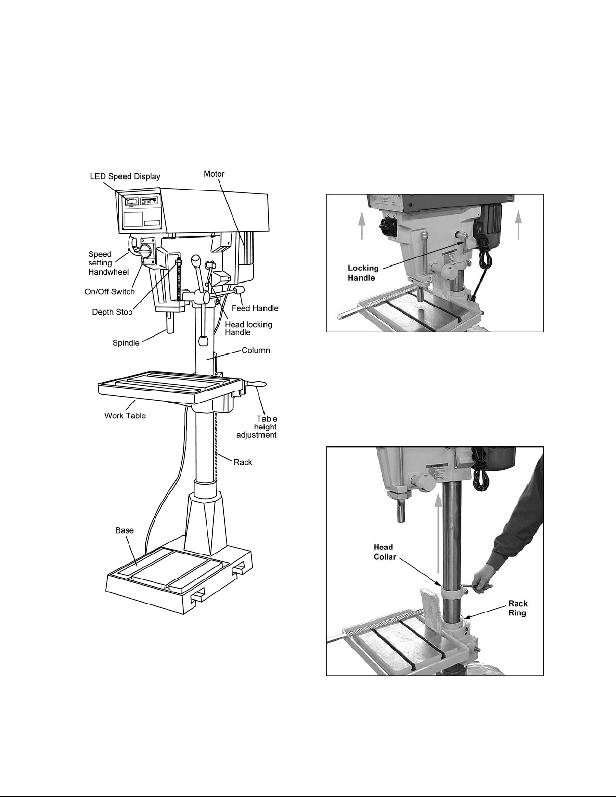
Refer to Figure 1 for key features of the drill
press.
Figure 1 – Drill Press Feat ur es
Set-up and Assembly
Securing the Base
The base of the drill press has four mounting
holes. The drill press should be level and rest
solidly on the fl oor. Place shim s under the f our
mounting hol es in the base as requi red to level
the drill press.
Assembly
The Drill Press is shipped with the head in
lowered position. Follow these instructions to
assemble.
1. Figure 2: Loosen locking handle on head
and raise the head toward the top of the
column. NOTE: Use an assistant to help
raise the head. Re-ti ghten locking handl e to
secure head in position.
Figure 2
2. Figure 3: Use a wrench to loosen the hex
screw on the head c ollar, and r aise the head
collar until it is contacting the head. Firmly
tighten the screw on the head collar.
3. Figure 3: Loo sen the set screw on t he rack
ring and raise rack ring to allow clearance
for the rack. Re-tighten the set screw.
Figure 3
Loading...