

Jet GH-1440ZX, GH-1460ZX, GH-1440ZX-EVS, GH-1660ZX, GH-1840ZX Operating Instructions Manual
...
Operating Instructions
ZX Series Lathes
Models GH-1440ZX/1440ZX-EVS/1460ZX
GH-1640ZX/1660ZX
GH-1840ZX/1860ZX/1880ZX
GH-2280ZX
WMH TOO L GR OU P, Inc.
427 New Sanford Road
LaVergne, TN 37086 Part No. M-321910
Ph.: 800-274-6848 Revision H 05/09
www.jettools.com Copyright © 2009 WM H Tool Group, Inc.

Warranty and Service
WMH Tool Group, Inc., warrants every product it sells. If one of our tools needs service or repair, one of our
Authorized Service Centers located throughout the United States can give you quick service. In most cases, any of
these WMH Tool Group Authorized Service Centers can authorize warranty repair, assist you in obtaining parts, or
perform routine maintenance and major repair on your JET
your area call 1-800-274-6848.
MORE INFORMATION
WMH Tool Group is consistently adding new products to the line. For complete, up-to-date product information, check
with your local WMH Tool Group distributor, or visit jettools.com.
WARRANTY
JET products carry a limited warranty which varies in duration based upon the product (MW = Metalworking, WW =
Woodworking).
WHAT IS COVERED?
This warranty covers any defects in workmanship or materials subject to the exceptions stated below. Cutting tools,
abrasives and other consumables are excluded from warranty coverage.
WHO IS C OVERE D?
This warranty covers only the initial purchaser of the product.
WHAT IS THE PERIOD OF COVERAGE?
The general JET warranty lasts for the time period specified in the product literature of each product.
WHAT IS NOT COVERED?
Five Year Warranties do not cover woodworking (WW) products used for commercial, industrial or educational
purposes. Woodworking products with Five Year Warranties that are used for commercial, industrial or education
purposes revert to a One Year Warranty. This warranty does not cover defects due directly or indirectly to misuse,
abuse, negligence or accidents, normal wear-and-tear, improper repair or alterations, or lack of maintenance.
HOW TO GET SERVICE
The product or part must be returned for examination, postage prepaid, to a location designated by us. For the name
of the location nearest you, please call 1-800-274-6848.
You must provide proof of initial purchase date and an explanation of the complaint must accompany the
merchandise. If our inspection discloses a defect, we will repair or replace the product, or refund the purchase price,
at our option. We will return the repaired product or replacement at our expense unless it is determined by us that
there is no defect, or that the defect resulted from causes not within the scope of our warranty in which case we will,
at your direction, dispose of or return the product. In the event you choose to have the product returned, you will be
responsible for the shipping and handling costs of the return.
HOW STATE LAW APPLIES
This warranty gives you specific legal rights; you may also have other rights which vary from state to state.
LIMITATIONS ON THIS WARRANTY
WMH TOOL GROUP LIMITS ALL IMPLIED WARRANTIES TO THE PERIOD OF THE LIMITED WARRANTY FOR
EACH PRODUCT. EXCEPT AS STATED HEREIN, ANY IMPLIED WARRANTIES OR MERCHANTABILITY AND
FITNESS ARE EXCLUDED. SOME STATES DO NOT ALLOW LIMITATIONS ON HOW LONG THE IMPLIED
WARRANTY LASTS, SO THE ABOVE LIMITATION MAY NOT APPLY TO YOU.
WMH TOOL GROUP, INC., SHALL IN NO EVENT BE LIABLE FOR DEATH, INJURIES TO PERSONS OR
PROPERTY, OR FOR INCIDENTAL, CONTINGENT, SPECIAL, OR CONSEQUENTIAL DAMAGES ARISING FROM
THE USE OF OUR PRODUCTS. SOME STATES DO NOT ALLOW THE EXCLUSION OR LIMITATION OF
INCIDENTAL OR CONSEQUENTIAL DAMAGES, SO THE ABOVE LIMITATION OR EXCLUSION MAY NOT APPLY
TO YOU.
WMH Tool Group sells through distributors only. The specifications in WMH catalogs are given as general information
and are not binding. Members of WMH Tool Group reserve the right to effect at any tim e, without prior notice, those
alterations to parts, fittings, and accessory equipment which they may deem necessary for any reason whatsoever.
® branded products are not sold in Canada by WMH Tool Group.
JET
® t ools. For the name of an Authorized Service Center in
2

Table of Contents
Warranty and Servic e .............................................................................................................................. 2
Table of Contents .................................................................................................................................... 3
Warning ................................................................................................................................................... 4
Specifications – 14” Lathes ...................................................................................................................... 6
Specifications – 16” Lathes ...................................................................................................................... 7
Specifications – 18” Lathes ...................................................................................................................... 8
Specifications – 22” Lathes ...................................................................................................................... 9
Unpac king ............................................................................................................................................. 10
Contents of the Shipping Container .................................................................................................... 10
Uncrating and Cleanup .......................................................................................................................... 11
Chuck Preparation (Three Jaw) .......................................................................................................... 11
Lubrication ......................................................................................................................................... 12
Coolant Prepar ation ........................................................................................................................... 13
Electri c al Connec tions ........................................................................................................................... 13
Conversion to 460 Volt Operation ....................................................................................................... 14
General Description ............................................................................................................................... 14
Lathe Bed .......................................................................................................................................... 14
Headstock .......................................................................................................................................... 14
Carriage ............................................................................................................................................. 15
Four Way Tool Post ........................................................................................................................... 15
Apron ................................................................................................................................................. 15
Tailsto ck ............................................................................................................................................ 1 5
Leadscrew and Feed Rod .................................................................................................................. 15
Feed Gearbox .................................................................................................................................... 15
Steady Rest ....................................................................................................................................... 15
Follow Rest ........................................................................................................................................ 16
Controls ................................................................................................................................................. 16
Operation .............................................................................................................................................. 1 9
Feed and Thread Selection ................................................................................................................ 19
Thread Cutting ................................................................................................................................... 19
Gib Adjustments................................................................................................................................. 1 9
Tailsto ck O ff- Se t ................................................................................................................................ 1 9
Removing Gap Section ...................................................................................................................... 20
Installing Removable Gap Section ...................................................................................................... 20
Belt Replacem ent and Adjustment...................................................................................................... 20
Aligning Tailstock to Headstock .......................................................................................................... 20
3

Warning
1. Read and understand the ent ire owners manual before attempting assembly or operation.
2. Read and understand the warnings po sted on the m achine and i n thi s manual. Fail ure to comply wit h
all of these warnings m ay cause seriou s i njury.
3. Replace the warning labels if they become obscured or remov ed.
4. This lathe is designed and int ended for use by properly trained and experienc ed personnel only. If
you are not f amiliar wit h the pr oper and saf e operat ion of a lathe, do not use until proper t rai ning and
knowledge have been obtained.
5. Do not use this lathe f or other than its i ntended use. If used for other purposes, W MH Tool Group
disclaim s any real or i mplied warrant y and h olds itsel f harml ess from any injury t hat may r esult f rom
that use.
6. Always wear approv ed safety glasses/fac e shields whil e using this lat he. Everyday eyeglasses only
have impact resistant lenses; they are not saf ety glasses.
7. Before operating t his lat he, rem ove tie, r ings, watches and other j ewelr y, and r oll sleev es up past the
elbows. Remove all loose clothing and confine long hair . Non-slip f ootwear or anti - skid floor stri ps are
recommended. Do not wear gloves.
8. Wear ear protector s (plugs or muffs) during ext ended periods of operation.
9. Some dust created by power sanding, sawing, grinding, drilling and other construction activities
contain chemi cals known to cause cancer , bir th defects or other r eproductiv e harm . Some exampl es
of these chemic als are:
• Lead from lead based paint.
• Crystalli ne sil ic a from bricks, cement and other masonry products.
• Arsenic and chromium from chemically treated lum ber .
Your risk of exposure varies, depending on how often you do this type of work. To reduce your
exposure to these chemicals, work in a well-ventilated area and work with approved safety
equipment, such as face or dust masks that are specifically designed to filter out microscopic
particles.
10. Do not operate this machine while tired or under the influence of dr ugs, alcohol or any medication.
11. Make certain the switch is in the OFF position before connecting the m achi ne to t he power supply .
12. Make certain the machine is properly grounded.
13. Make all machine adjustments or maintenance with t he machine unplugged from the power source.
14. Remove adjusting keys and wrenches. Form a habit of checking to see that keys and adjusting
wrenches are removed from the machine before turning it on.
15. Keep safety guards in place at all times when the machine is in use. If removed for maintenance
purposes, use extreme caution and replac e the guards immediately.
16. Check damaged parts. Before further use of the machine, a guard or other part that is damaged
should be carefully checked to determine that it will operate properly and perform its intended
function. Chec k for alignment of moving par ts, binding of moving parts, breakage of parts, mounting
and any other condi ti ons that m ay affect its operati on. A guard or ot her part that i s damaged should
be properly repaired or replaced.
17. P rovide for adequate space surrounding work area and non-glare, overhead lighting.
18. K eep the floor around the m achi ne clean and free of scrap material, oil and grease.
19. K eep visitors a safe di st anc e from the work area. Keep children away.
20. Make your workshop chil d pr oof with padlocks, master switc hes or by removing starter keys.
4

21. Giv e your work undivi ded attention. Looki ng around, carryi ng on a conversati on and “horse-play” ar e
careless acts that can r esul t in serious injury.
22. M aintain a balanc ed stance at all t imes so that you d o not fall or lean against mov ing parts. Do not
overreach or use exc essive force to perform any machine operation. Never force the cutt ing action.
23. Use the ri ght t ool at the cor rect speed and f eed rate. Do not for ce a tool or attachm ent to do a j ob for
which it was not designed. T he ri ght tool will do the job better and safer.
24. Use rec om mended accessories; i mproper accessories may be hazardous.
25. Maintain tools with care. Keep cutting tools sharp and clean for the best and safest performance.
Follow instructions for lubricating and changing accessories.
26. Do not attempt to adjust or remov e tools during operation.
27. Tur n off the machi ne and disconnect f rom power bef ore cleani ng. Use a brush to remove shavi ngs or
debris — do not use your hands.
28. Do not stand on the machine. S eri ous injury could occur if the machine tips over.
29. Never leave the m ac hine r unning unattended. Turn the power off and do not l eav e the mac hine until it
comes to a complete stop.
30. Remove loose item s and unnecessary work pieces from the area before starting the machine.
Familiariz e you rself with the following safety notices used in this manual :
This means that if precautions are not heeded, it may result in minor injury and/or
possible machine damage.
This means that if precautions are not heeded, it may result in serious injury or possibly
even death.
- - SAVE THESE INSTRUCTIONS - -
5

The following specificati ons were current at the time this manual was published, but becau se of our poli cy
of continuous improvement, WMH Tool Group, Inc. reserv es the r ight to change specifications at any time
and without pri or notice, without incurri ng obligations.
Specifications – 14” Lathes
Model Number ......................................... GH-1440ZX ............. GH-1440ZX-EVS ....................GH-1460ZX
Stock Number................................................. 321910 ............................ 321900 .......................... 321920
Capacities:
Swing over Bed (in.) ...............................................14 .................................... 14 .................................. 14
Swing over Cross Slide (in.) ............................... 7-5/8 ................................ 7-5/8 .............................. 7 -5/8
Swing Through Gap (in.) ...................................23-5/8 .............................. 23-5/8 ............................ 23-5 /8
Length of Gap (in.) ............................................12-1/4 .............................. 1 2-1/4 ............................ 12-1/4
Distance between Centers (in.) ...............................40 .................................... 40 .................................. 60
Headstock:
Spindle Bore (in.) ............................................... 3-1/8 ................................ 3-1/8 .............................. 3- 1/8
Spindle Mount .................................................... D1-8 ................................ D1-8 ...............................D1-8
Spindle Taper with Sleeve ....................... MT-7(MT-5) ..................... MT-7(MT-5) ....................MT-7(MT-5)
Number of Spindl e Speeds .....................................12 .................................... 1 2 .................................. 12
Range of Spindle Speeds (RPM ) ............... 42 to 1800 ........................40 to 2000 ...................... 42 to 1800
Gearbox:
Number of Longitudinal and Cross Feeds .............1 22 .................................. 122 ................................ 122
Range of Longitudinal Feeds (in./rev .) 0.0015 to 0.0913 .......... 0.0015 to 0.0913 ............ 0.0015 to 0.0913
Range of Cross Feeds (in. /rev.) ....... 0.0006 to 0.0365 .............. 0.0006 to 0.0365 ............ 0.0006 to 0.0365
Number of Inch Threads .........................................61 .................................... 61 .................................. 61
Range of Inch Threads (in.) ....................... 1-5/8 to 72 ....................... 1-5/8 to 72 ..................... 1-5/8 to 72
Number of Metric Threads ......................................24 .................................... 24 .................................. 24
Range of Metric Threads (mm) ................... 0.05 to 20 .........................0.05 to 20 ....................... 0.05 to 20
Compound and Carriage:
Maximum Tool Size (in.) ..................................... 1 x 1 ................................ 1 x 1 ...............................1 x 1
Maximum Compound Slide Travel (in.) .............. 5-1/8 ................................ 5-1 /8 .............................. 5-1/8
Maximum Cross Slide Travel (in.) ............................ 9 ...................................... 9 .................................... 9
Carriage Tr av el (i n.) ................................................35 .................................... 35 .................................. 55
Tailstock:
Tailstock Spindle Travel (in.) .................................... 5 ...................................... 5 .................................... 5
Tailstock Taper .................................................. MT-4 ................................ MT-4 .............................. MT-4
Steady Rest Capaci ty (in.) ........................ 1/2 to 3-1/2 ...................... 1/2 to 3-1/2 .................... 1/2 to 3-1/2
Follow Rest Capacit y (i n.) ............................... 3/8 to 7 ............................ 3/8 to 7 .......................... 3/8 to 7
Width of Bed (in.) ..............................................13-3/8 .............................. 13-3/8 ............................ 13-3/8
Overall Dimensions(in.)(LxWxH) . 97-1/2 x 40 x 46-7/8 ......... 97-1/2 x 40 x 46-7/8 ..... 116-1/2 x 40 x 46-7/8
Motor .................................... 7-1/2HP,3Ph,230/460V* ... 7-1/2HP,3Ph,230/460V* . 7-1/2HP,3Ph,230/460V*
Approximate Net Weight (lbs.) ............................ 5187
................................ 5187 .............................. 5380
*pre-wired 230V
6

Specifications – 16” Lathes
Model Number .......................................................................GH-1640ZX ...............................GH-1660ZX
Stock Number.............................................................................. 321930 ..................................... 321940
Capacities:
Swing over Bed (in.) ............................................................................ 16 ............................................. 16
Swing over Cross Slide (in.) ................................................................. 10 ............................................. 10
Swing Through Gap (in.) ................................................................ 25-7/8 ....................................... 25- 7/8
Length of Gap (in.) ......................................................................... 12-1/4 ....................................... 12-1 /4
Distance between Centers (in.) ............................................................ 40 ............................................. 60
Headstock:
Spindle Bore (in.) ............................................................................. 3 - 1 /8 ......................................... 3-1/8
Spindle Mount ..................................................................................D1-8 ..........................................D1-8
Spindle Taper with Sleeve .....................................................MT-7(MT-5 ) ...............................MT-7(MT-5 )
Number of Spindl e Speeds .................................................................. 12 ............................................. 12
Range of Spindle Speeds (RPM ) ............................................. 25 to 1800 ................................. 25 to 1800
Gearbox:
Number of Longitudinal and Cross Feeds .......................................... 1 22 ........................................... 12 2
Range of Longitudinal Feeds (in./rev .) ........................... 0.0015 to 0.0913 ....................... 0.0015 to 0.0913
Range of Cross Feeds (in. /rev.) ..................................... 0.0006 to 0. 0365 ....................... 0.0006 to 0.0365
Number of Inch Threads ...................................................................... 61 ............................................. 61
Range of Inch Threads (in.) .................................................... 1-5/8 to 72 ................................ 1-5/8 to 72
Number of Metric Threads ................................................................... 24 ............................................. 24
Range of Metric Threads (mm) ................................................. 0.05 to 20 .................................. 0.05 to 20
Compound and Carriage:
Maximum Tool Size (in.) ...................................................................1 x 1 ..........................................1 x 1
Maximum Compound Slide Travel (in.) ............................................ 5- 1/8 ......................................... 5-1/8
Maximum Cross Slide Travel (in.) .......................................................... 9 ............................................... 9
Carriage Tr av el (i n.) ............................................................................. 35 ............................................. 55
Tailstock:
Tailstock Spindle Travel (in.) .................................................................. 5 ............................................... 5
Tailstock Taper ................................................................................ MT-4 ......................................... MT-4
Steady Rest Capaci ty (in.) ..................................................... 1/2 to 3-1/2 ............................... 1/2 to 3-1/2
Follow Rest Capacit y (i n.) ............................................................ 3/8 to 7 ..................................... 3/8 to 7
Width of Bed (in.) ........................................................................... 13-3/8 ....................................... 13-3/8
Overall Dimensions (in.)(LxWxH) .................................... 97-1/2 x 40 x 48 ...................... 116-1/2 x 40 x 48
Motor ................................................................ 7-1/2HP, 3Ph, 230/460V* .......... 7-1/2 HP, 3Ph, 230/460V*
Approximate Net Weight (lbs.) ......................................................... 5475 ......................................... 5795
*pre-wired 230V
7

Specifications – 18” Lathes
Model Number .................................................... GH-1840ZX ............... GH-1860ZX ...............GH-1880ZX
Stock Number............................................................ 321950 ...................... 321960 ..................... 321970
Capacities:
Swing over Bed (in.) ......................................................... 18 .............................. 18 ............................. 18
Swing over Cross Slide (in.) .............................................. 11 .............................. 11 ............................. 11
Swing Through Gap (in.) ............................................. 27-1/2 ........................ 27-1/2 ....................... 27-1 /2
Length of Gap (in.) ...................................................... 12-1/4 ........................ 12-1/4 ....................... 12-1/4
Distance between Centers (in.) ......................................... 40 .............................. 60 ............................. 8 0
Headstock:
Spindle Bore (in.) .......................................................... 3-1/8 .......................... 3-1/8 ......................... 3-1/8
Spindle Mount ............................................................... D1-8 .......................... D1-8 ..........................D1-8
Spindle Taper with Sleeve .................................. MT-7(MT-5) ............... MT-7(MT-5) ...............MT-7(MT-5)
Number of Spindl e Speeds ............................................... 12 .............................. 12 ............................. 12
Range of Spindle Speeds (RPM ) .......................... 25 to 1800 ................. 25 to 1800 ................. 25 to 1800
Gearbox:
Number of Longitudinal and Cross Feeds ....................... 1 2 2 ............................ 122 ........................... 12 2
Range of Longitudinal Feeds (in./rev .) ........ 0.0015 to 0.0913 ........ 0. 0015 to 0.0913 ....... 0.0015 to 0.0913
Range of Cross Feeds (in. /rev.) .................. 0.0006 to 0. 0365 ........ 0.0006 to 0.0365 ....... 0.0006 to 0.0365
Number of Inch Threads ................................................... 61 .............................. 61 ............................. 61
Range of Inch Threads (in.) .................................. 1-5/8 to 72 ................. 1-5/8 to 72 ................ 1-5/8 to 72
Number of Metric Threads ................................................ 24 .............................. 24 ............................. 24
Range of Metric Threads (mm) .............................. 0.05 to 20 .................. 0.05 to 20 .................. 0.05 t o 20
Compound and Carriage:
Maximum Tool Size (in.) ................................................ 1 x 1 .......................... 1 x 1 ..........................1 x 1
Maximum Compound Slide Travel (in.) ......................... 5-1/8 .......................... 5-1/8 ......................... 5-1/8
Maximum Cross Slide Travel (in.) ....................................... 9 ................................ 9 ............................... 9
Carriage Tr av el (i n.) .......................................................... 35 .............................. 55 ............................. 75
Tailstock:
Tailstock Spindle Travel (in.) ............................................... 5 ................................ 5 ............................... 5
Tailstock Taper ............................................................. MT-5 .......................... MT-5 ......................... MT-5
Steady Rest Capaci ty (in.) ................................... 1/2 to 3-1/2 ................ 1/2 to 3-1/2 ............... 1/2 to 3-1/2
Follow Rest Capacit y (i n.) .......................................... 3/8 to 7 ...................... 3/8 to 7 ..................... 3/8 to 7
Width of Bed (in.) ........................................................ 13-3/8 ........................ 13-3/8 ....................... 13-3/8
Overall Dimensions (in.)(LxWxH) ............... 97-1/2x40x48-7/8 ..... 116-1/2x40x48-7/8 ....
Motor ............................................................... 7-1/2HP, 3Ph ............. 7-1/2HP, 3Ph ............ 7-1/2HP, 3Ph
............................................................................. 230/460V* ................. 230/460V* ................. 230/460V*
Approximate Net Weight (lbs.) .......................................5980 .......................... 6245 ......................... 6590
136-1/8x40x48-7/8
*pre-wired 230V
8

Specifications – 22” Lathes
Model Number .........................................................................................................................GH-2280ZX
Stock Number................................................................................................................................ 321980
Capacities:
Swing over Bed (in.) .............................................................................................................................. 2 2
Swing over Cross Slide (in.) ................................................................................................................... 11
Swing Through Gap (in.) .................................................................................................................. 27-1/2
Length of Gap (in.) ........................................................................................................................... 12-1/4
Distance between Centers (in.) .............................................................................................................. 80
Headstock:
Spindle Bore (in.) ............................................................................................................................... 3-1/8
Spindle Mount ....................................................................................................................................D1-8
Spindle Taper with Sleeve .......................................................................................................MT-7(MT-5)
Number of Spindl e Speeds .................................................................................................................... 12
Range of Spindle Speeds (RPM ) ............................................................................................... 25 to 1800
Gearbox:
Number of Longitudinal and Cross Feeds ............................................................................................ 1 22
Range of Longitudinal Feeds (in./rev .) ............................................................................. 0.0015 to 0.0913
Range of Cross Feeds (in. /rev.) ....................................................................................... 0.0006 to 0.0365
Number of Inch Threads ........................................................................................................................ 61
Range of Inch Threads (in.) ...................................................................................................... 1-5/8 to 72
Number of Metric Threads ..................................................................................................................... 24
Range of Metric Threads (mm) ................................................................................................... 0.05 to 20
Compound and Carriage:
Maximum Tool Size (in.) .....................................................................................................................1 x 1
Maximum Compound Slide Travel (in.) .............................................................................................. 5- 1/8
Maximum Cross Slide Travel (in.) ............................................................................................................ 9
Carriage Tr av el (i n.) ............................................................................................................................... 75
Tailstock:
Tailstock Spindle Travel (in.) .................................................................................................................... 5
Tailstock Taper .................................................................................................................................. MT-5
Steady Rest Capaci ty (in.) ....................................................................................................... 1/2 to 3-1/2
Follow Rest Capacit y (i n.) .............................................................................................................. 3/8 to 7
Width of Bed (in.) ............................................................................................................................. 13-3/8
Overall Dimensions (in.)(LxWxH) .............................................................................. 136-1/8 x 40 x 48-7/8
Motor .......................................................................................... 10HP, 3PH, 230V/460V (pre- wir ed 230V )
Approximate Net Weight (lbs.) ........................................................................................................... 7400
9

Unpacking
Open shipping cont ainer and check f or shipping
damage. Report any damage immediately to
your distributor and shipping agent. Do not
discard any shipping material until the Lathe is
assembled and running properly.
Compare the c ontent s of y our cont ainer wit h t he
following parts list to make sure all parts are
intact. Mi ssing parts, if any, should be reported
to your distributor. Read the instruction manual
thoroughly for assembly, maintenance and
safety instructions.
Contents of the Shipping Container
1 Lathe
1 Steady Rest (mount ed on Lathe)
1 Follow Rest (mounted on Lathe)
1 10” Three Jaw Chuck (mount ed on Lathe)
1 12” Four Jaw Chuck
1 Face Plate (12” Fac e Pl ate f or 14” & 16”
lathes; 16” F ac e Plate for 18” & 22” lathes)
1 Tool Box containing:
1 Open End Wrench Set
1 Hex Wrench Set
1 Morse Reduction Sleeve
1 Center
6 Leveling Bolts with Hex Nuts
6 Leveling Pads
1 Flat Blade Scr ewdriver
1 Cross Point Screwdriver
1 Chuck Wrench
1 Tool Post Wrench
1 Cam Wrench
1 Adjustable Wrench
1 Round Nut Wrench
1 Oil Gun
1 Cross Feed Handle (not shown)
2 Shear Pins (not shown)
1 Gap Bridge Pin Driver
1 Live Center (MT 4 for 14” & 16” lathes;
MT5 for 18” & 22” lathes)
1 Operating Instructions Manual
1 Parts List Manual
1 Test Record
1 Warranty Card
Read and understand the entire contents of this manual before attempting set-up
or operation! Failure t o co mply may cause serious injury.
contents of Tool Box
10
Uncrating and Cleanup
1. Finish removing the wooden crate from
around the lathe.
2. Unbolt the lathe from the shipping crate
bottom.
3. Choose a location f or the lathe that is dry,
has good light ing, and has enough room t o
allow servicing the lathe on all four sides.
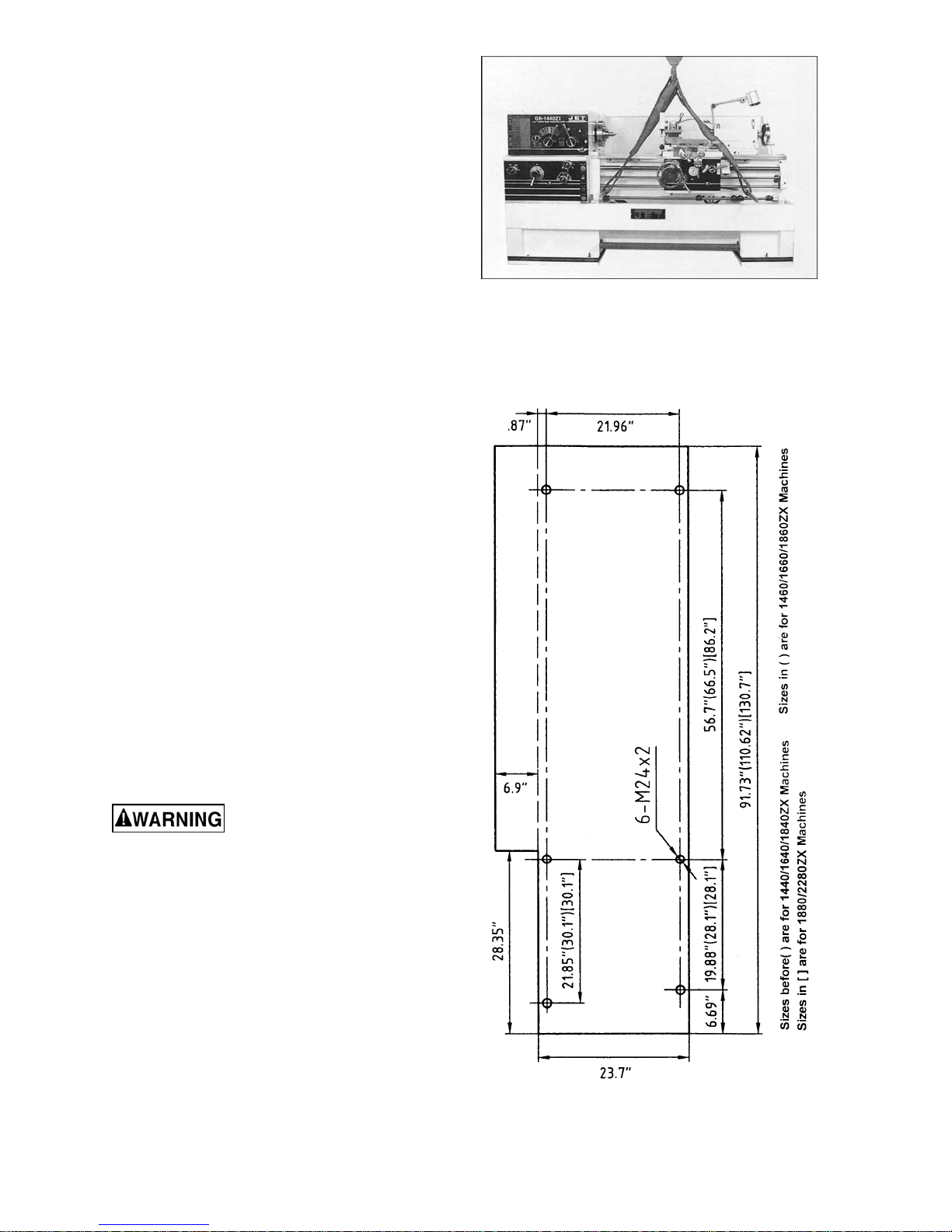
4. Sling t he lathe as shown i n Figure 1, using
steel rods or pipes of sufficient strength
inserted through the holes in the bed
casting. Do not lift lathe by the spindle.
With adequate lifting equipment, slowly
raise the lat he off the shipping cr ate bot tom .
Make sure lathe is balanc ed before moving.
5. To avoid twisting the bed, the lathe’s
location must be absolutely flat and level.
Check for a level condition using a
machinist’s precision level on the bedways
both front to back and side to side. The
leveling pads included in the tool box and
the leveling screws in the lathe base will
help you to reach a level condition. The
lathe must be level to be accurate.
Figure 1
6. Clean all rust protected surfaces using a
mild commer cial solvent , kerosene or di esel
fuel. Do not use paint thinner, gasoline, or
lacquer thi nner. These will dam age painted
surfaces. Cov er all cleaned surf aces with a
light film of 2 0W machine oil .
7. Open the end gear cover. Clean all
components of the end gear assembly and
coat all gears with a heavy, non-slinging
grease. Close the end gear cover.
Chuck Preparation (Three Jaw)
Read and understand all
directions for chuck preparation. Failure to
comply may cause serious injury and/or
damage to the lath e.
NOTE: Before removing the chuck from the
spindle, place a flat piece of wood (plywood,
etc.) across the bedways under the chuck to
prevent damage to the bedways should the
chuck fall from your hands.
To remove the chuck:
1. Support the chuck while turning six
camlocks 1/4 t urn countercl ockwise with the
chuck wrench fr om the tool box.
2. Carefully remove t he chuck from the spindl e
and place on an adequate work surface.
Figure 2
11
3. Inspect the cam lock studs. Make sure they
have not become crac ked or broken during
transit. Clean all parts thoroughly with
solvent. Also clean the spindle and
camlocks.
4. Cover all chuck jaws and scroll inside the
chuck with #2 li thium tube grease. Cov er the
spindle, camlocks, and chuck body with a
light film of 2 0W oil.
5. Lift the chuck up to the spindle nose and
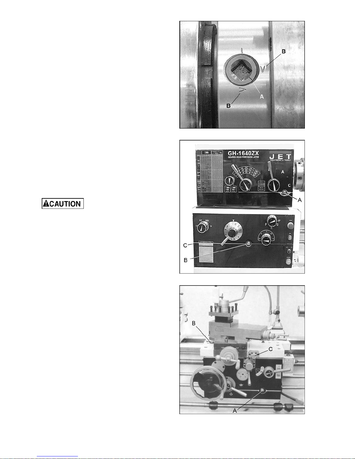
press onto the spindle. Tighten in place by
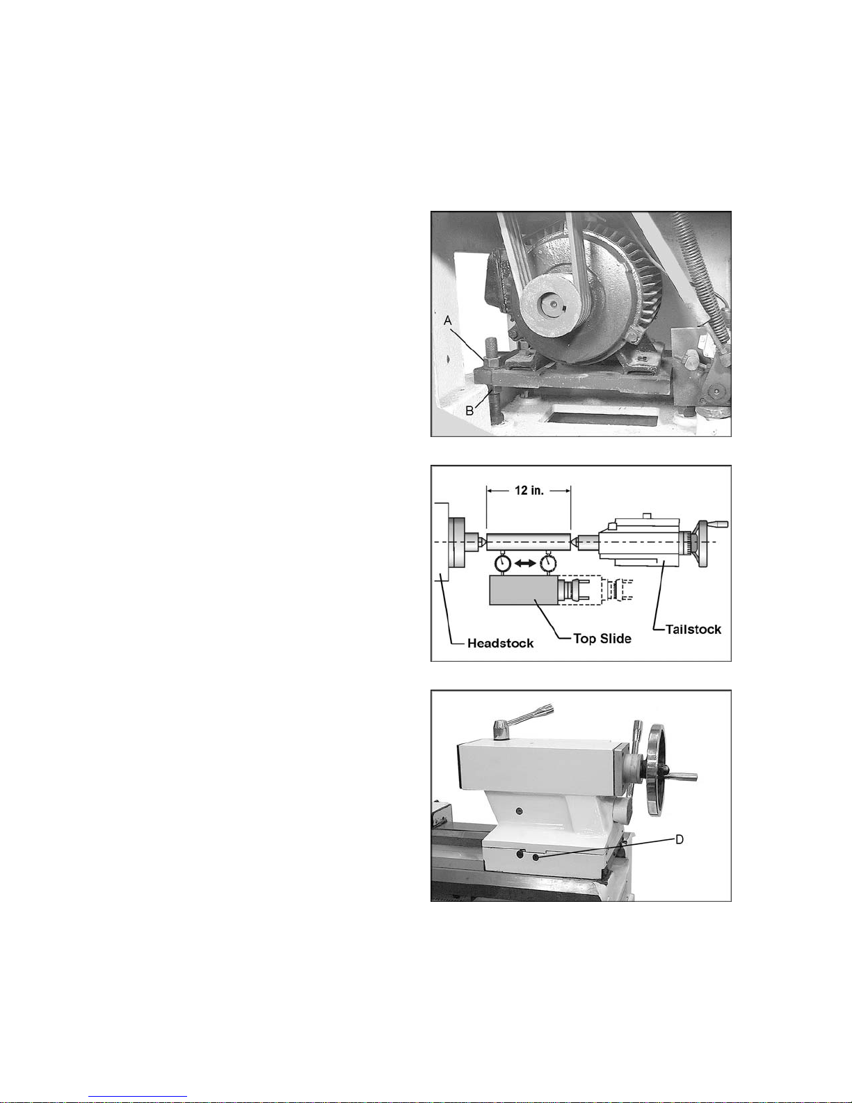
turning the camlocks 1/4 turn cl oc k wise. The
index mark (A, Figure 3) on the camlock
should be between the t wo indicator ar rows
when tight ( B, Fi gure 3). If the i ndex m ark is
not between the two arrows, remove the
chuck and adjust the camlock studs by
either turning out one full turn (if cams will
not engage) or turning in one full turn (if
cams turn beyond indic ator marks.)
6. Install chuck and tighten in place.
Lubrication
Figure 3
L athe must be serviced at all
lubrication points and all reservoi rs filled to
operating level before the lathe is put into
service. Failure to comply may cause serious
damage to the lath e.
1. Headstock – Oil must be up to indicator
mark in oil sight gl ass (A, Figure 4). Top off
with Mobil DTE® Oil Heav y Medium. Fill by
removing the pl ug on top of the headstock.
To drain, remove drain pl ug on the left si de
of the headstock at the lower rear corner.
Drain oil com pletely and clean out all met al
shavings. Refill after the first month of
operation. Then change the oil in the
headstock every two months.
2. Gearbox – Oil must be up to indi cator mark
in oil sight gl ass (B, Figure 4). Top off with
Mobil DTE® Oil Heavy Medium. To add oil
to the gearbox, remove two screws on the
top cover and remove cover. To drain,
remove drain plug (C, Figure 4) on the left
side of the gearbox. Drain oil completely
and refill after the first three months of
operation. Then change oil in the gearbox
every six mont hs.
Figure 4
3. Apron – Oil must be between indicator
marks in the oil sight glass (A, Figure 5).
Top off with Mobil DTE ® Oil Heavy Medium.
Remove oil plug (B, Figure 5) to fill. To
drain, remove drain plug on bottom of
apron.
Figure 5
12
Drain oil completely and refill after the first
three mont hs of operati on. Then, c hange oil
in the apron annually. Pull knob (C, Figure
5) on the one-shot lube sy stem and hol d for
several seconds t o allow oil to fill the pump.
When the knob is released, oil will flow
through various oil lines to lubricate the
ways and cross slide surface. Perform this
twice dail y or as needed. When t he oil l evel
is below the indicator mark, oil must be
added.
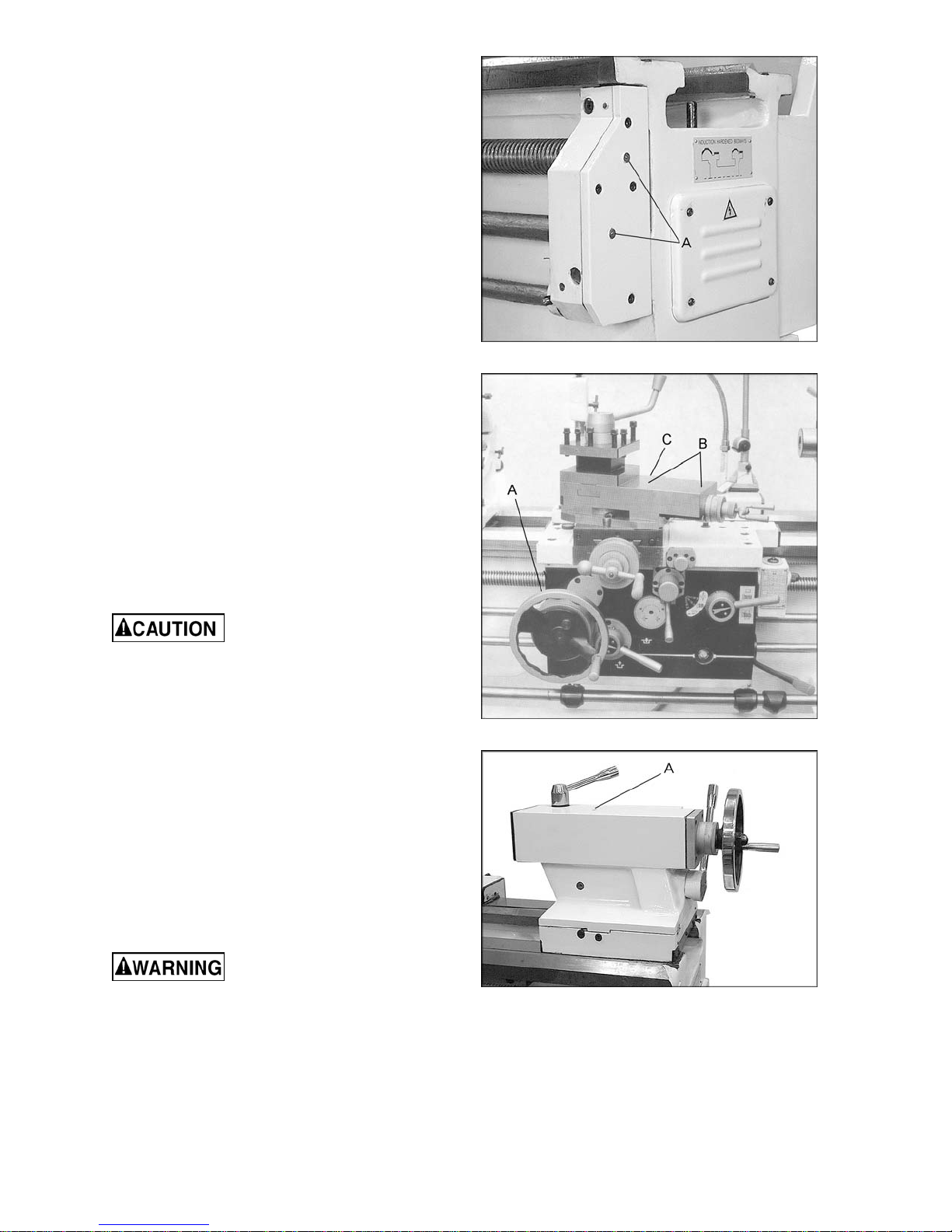
4. Leadscrew and Feed Rod – Lubricate two
ball oilers on the right side bracket (A,
Figure 6) with 30W machine oil daily.
5. Saddle – Daily lubri cate ball oiler (A, Figure
7) on handwheel shaft with M obil DTE® Oil
Heavy Medium.
6. Compound Rest – Daily lubricate two ball
oilers (B, Fi gur e 7) on top of compound slide
with Mobil DTE® Oil Heavy Medi um.
7. Cross Slide – Dail y lubricate one ball oiler
(C, Figure 7) with Mobil DTE® Oil Heavy
Medium.
8. Tailstock – Daily lubricate one ball oiler (A,
Figure 8) on top of tailstock with Mobil
DTE® Oil Heavy Medium.
Coolant Preparation
Follow coolant manu-
facturer’s recommendations for use, care
and dispos a l.
1. Remove access cover on tailstock end at
the rear base of the lathe. Make sure
coolant pump has not shifted during
transport.
2. Pour four gallons (approximate) of coolant
mix into the chip pan.
Figure 6
Figure 7
3. After machine has been connected to
power, turn on coolant pump and check to
see that coolant is cycli ng pr oper ly.
4. Replace access cover .
Electrical Connections
Electrical connections must
be made by a qualified electrician in
compliance with all relevant codes. This
machine must be properly grounded while in
use to help protect the operator from
electrical sho ck and po ssib le fatal injury.
Figure 8
13
The main motor is rated at 7-1/2 HP (or 10HP
for model 2280ZX), 230/460V and comes from
the factor y prewired at 230V. Confirm that power
available at the lathe’s location is the same
rating as the lat he.
Power is connected properly when rotating the
forward-reverse knob (E, Figure 12) to the left
position causes the spindle to rotate
countercl ockwise as v i ewed from the t ail stock. If
the chuck rotates in the clockwise direction,
disconnect the lathe from the power source,
switch any two of the thr ee power lead s (not t he
green ground wire), and re-connect the lathe to
the power source.
Conversion to 460 Volt Operation
Disconnect machine from
power source. Failure to do so may cause
serious injury.
Mai n Mo tor : Change the wire s accordi ng to the
diagram on the outside of the motor junction
box.
Transformer: Open electrical panel on rear of
machine on the headstock side. Switch wire
from 230V termi nal to 460V termi nal as outli ned
on the transf ormer.
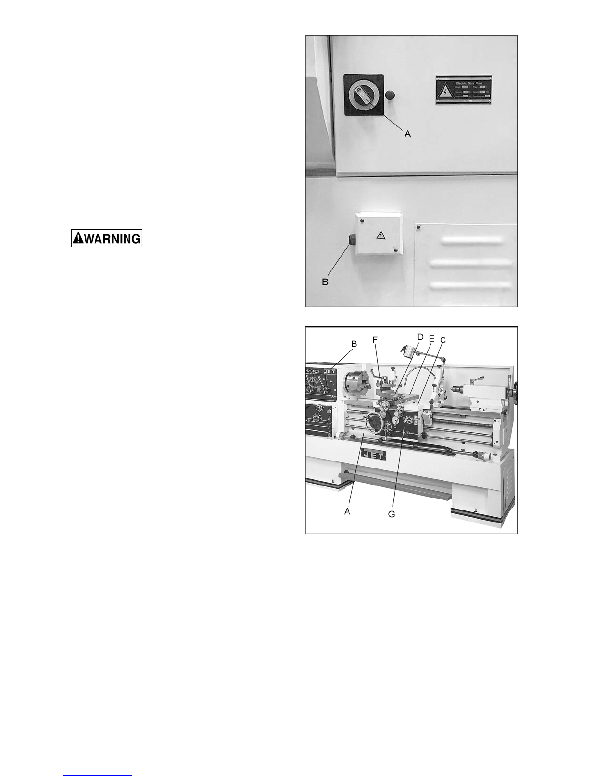
Figure 9
Coolant Pump: Open access panel on the base
at the tailstock end. Change wires in coolant
pump junction box according to diagram on the
outside of the junc tion box cover.
Main Power Switch (A, Figure 9): Turns power
to machine on and off.
Power Source Cabl e Receiver (B , Figure 9).
Make sure the lat he is properly grounded.
General Description
Lathe Bed
The lathe bed ( A , Fi gur e 10) is made of cast ir on
with low vibration and high rigidity. Two
precision ground v-slideways, reinforced by
induction hardening and grinding, are an
accurate guide for the carriage and headstock.
The main drive motor is mounted in the stand
below the the headstock.
Headstock
The headstock (B, Figure 10) is cast from high
grade, low vibr ation cast iron. It is bolted t o the
bed by four hex socket cap bolts. In the head,
the spindle i s mounted on precision t aper roller
bearings.
Figure 10
14
Carriage
The carriage (C, Figure 10) is made from high
quality cast ir on. The cross-slide (E, Figure 10)
is mounted on the carriage and moves on a
dovetail ed slide which can be adj usted for pl ay
by means of the gibs.
The compound sli de (D, Figure 10) which is Tslotted, and mounted on the cross slide (E,
Figure 10) c an be rotated 360°. The compound
slide and the cross slide travel in a dovetailed
slide and have adj ustable gibs.
Four Way Tool Post
The four way t ool post (F, Figure 10) is mounted
on the compound slide and allows a maximum
of four tools to be mounted at the same time.
Remember to use a mi nimum of two cl amping
screws when installing a cutting tool.
Apron
The apron (G, Figure 10) is mounted to the
carriage. Quick travel of the apron is
accomplished by m eans of a bed-mount ed rack
and pinion, operated by the handwheel on the
front of the apron.
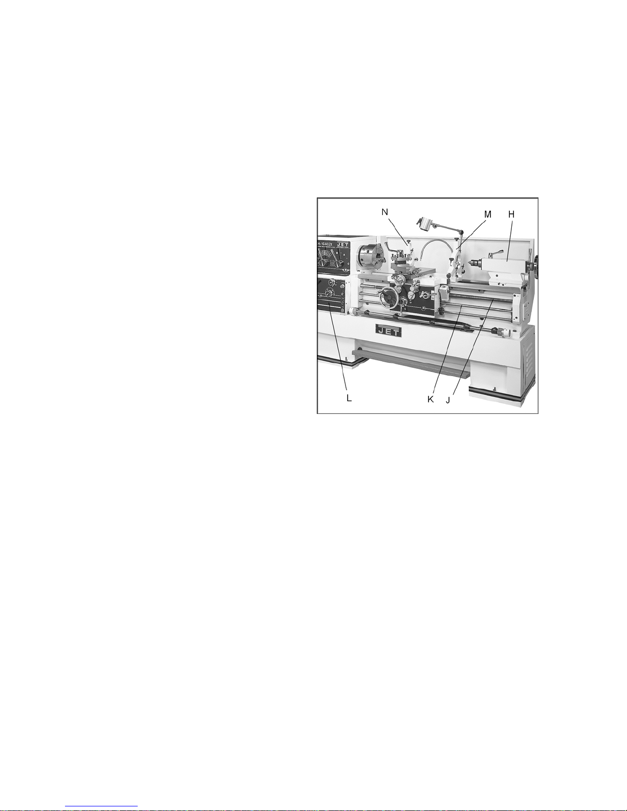
Tailstock
The tailstock (H, Figure 11) slides on a v-way
and can be locked at any locati on by a clamping
lever. T he tail stock has a heavy duty qui ll wit h a
Morse Taper #4, or Morse Taper #5 (18” and
22” models).
Leadscrew and Feed Rod
The leadscrew (J, Figure 11) and feed rod (K,
Figure 11) are mounted on the front of the
machine bed. They are connected to the
gearbox at the left and are supported by
bearings on both ends. Both ar e equipped with
shear pins.
Feed Gearbox
The gearbox (L, Figure 11) is made from high
quality cast i ron and is mounted to t he left side
of the machine bed.
Figure 11
Steady Rest
The steady rest (M, Figure 11) serves as a
support for shaf ts on the free tailstoc k end. The
steady rest is mounted on the bedway and
secured fr om below with a bol t, nut and loc king
plate. The sliding fingers require continuous
lubrication at the contact points with the
workpiece to prevent them from premature
wear.
15
To set the steady rest:
1. Loosen three hex sock et cap screws.
2. Loosen knurled screw and open sliding
fingers until the steady rest can be moved
with its fingers around the workpiece.
Secure the steady rest in position.
3. Set the fingers snugly t o the workpiece and
secure by tightening three hex socket cap
screws. Fingers should be snug but not
overly tight. Lubricate sliding points with
lead-based grease.
Follow Rest
The traveling follow rest (N, Figure 11) is
mounted on the saddle and follows the
movement of the turning tool. Only two fingers
are required a s the pl ace of t he thi rd i s taken by
the turning tool. The follow rest is used for
turning operat ions on long, slender workpieces.
It prev ents the workpiece f rom fl exing under the
pressure of t he cutting tool.
The slidi ng fingers are set simi lar to the steady
rest, free of play, but not binding. Always
lubricate adequately with lead-based grease
before operating.
Figure 11 (repeated)
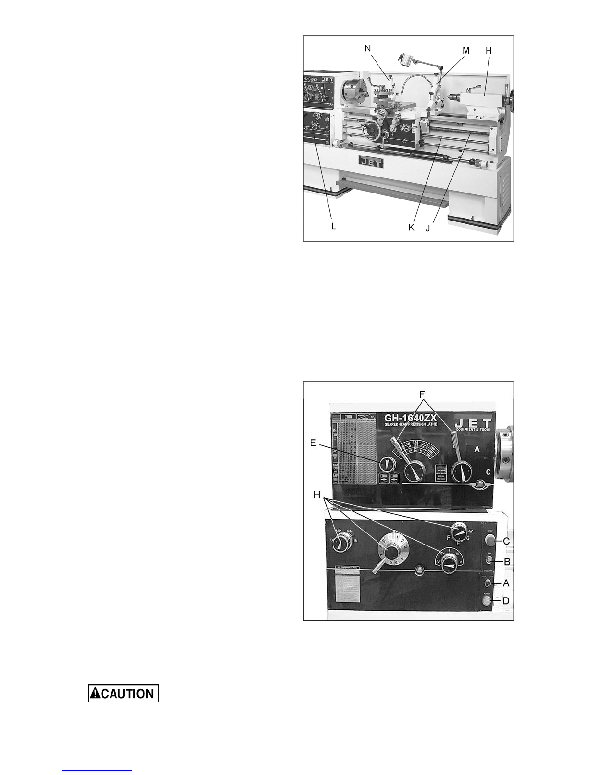
Controls
1. Control Panel: located on front of
headstock. [On EVS models, control panel
is located on a swivel post above the
headstock.]
• Coolant On-Off Switch (A, Figure 12)
turns coolant pum p on and off .
• Power Indicator Light (D, Figure 12) is lit
whenever lathe is receiving power.
• Emergency Stop Switch (C, Figure 12)
stops all machine functions (Caution:
Lathe will still have power). Twist
clockwise to re-set.
• Jog Switch (B, Figure 12). Quickly press
and release to rotate the spindle.
2. Headstock Gear Change Levers (F, Figure
12): Located on front of headstock. Move
levers left or right to desired spindle speed.
NOTE: The left handle is omitted on EVS
models.
3. Leadscrew/Feed Rod Directional Lever
(E, Figure 12): Located on front of
headstock at lower left. Changing knob
changes direction of feed.
Figure 12
Do not move knob while
machine is running.
16

4. Feed/Lead Selector Lever (H, Figure 12):
Located on f ront of headstock. Used when
setting up for thr eading or feeding.
5. Compound Slide (L, Figure 13) is located
on top of t he cross slide and c an be rotated
360°. There are c alibrations in degrees (M,
Figure 13) below the rest to assist in
placement of the compound slide to the
desired angle.
6. Compound Lock (not shown): Lever
located on back of compound slide. Turn
clockwise to lock and counterclockwise to
unlock.
7. Cross Slide Lock (A, Figure 13): Lever
located on left side of cross slide. Turn
clockwise to lock and counterclockwise to
unlock.
8. Carriage Lock (B, Figure 13): Located on
top right of carriage. Turn clockwise to lock,
countercl oc k wise to unlock.
Carriage lock must be
loose before moving carriage or damage
to lathe may occur.
9. Longitudinal Traverse Handwheel (C,
Figure 13): Located on the apr on assembl y.
Rotate handwheel clockwise to move the
apron assembl y toward the tai lstock (right).
Rotate the wheel count erclockwise to move
the apron assembly toward headstock (left).
10. Longitudinal/Cross Feed Selector Lever
(E, Figure 13): Can be pushed to upper,
middle and lower three positions. Push the
lever up, cross feed is effected. Push the
lever down, longitudinal feed is effected.
When the lever is in the middle position,
screws can be cut by engaging the half nut.
11. Half Nut Lever (D, Figure 13): Located on
the front of the apron assembly. Used for
threading.
12. Feed Engage Lever (G, Figure 13):
Located in the f ront of the apron assem bly.
Pull lever up to engage. Push lev er down to
disengage.
13. Adjustable Feed Clutch (F, Figure 13):
When the machine is ov erloaded, it can sli p.
Then cutting rate must be reduced. Note:
This setting has been calibrated at the
factory and should not need adjustment. If
adjustment ever becomes necessary, f ollow
the diagram on the front of t he apr on.
14. Cross Traverse Handwheel (H, Figure 13):
Located above the apron assembly.
Clockwise rotation moves the cross slide
toward the rear of mac hine.
Figure 13
17
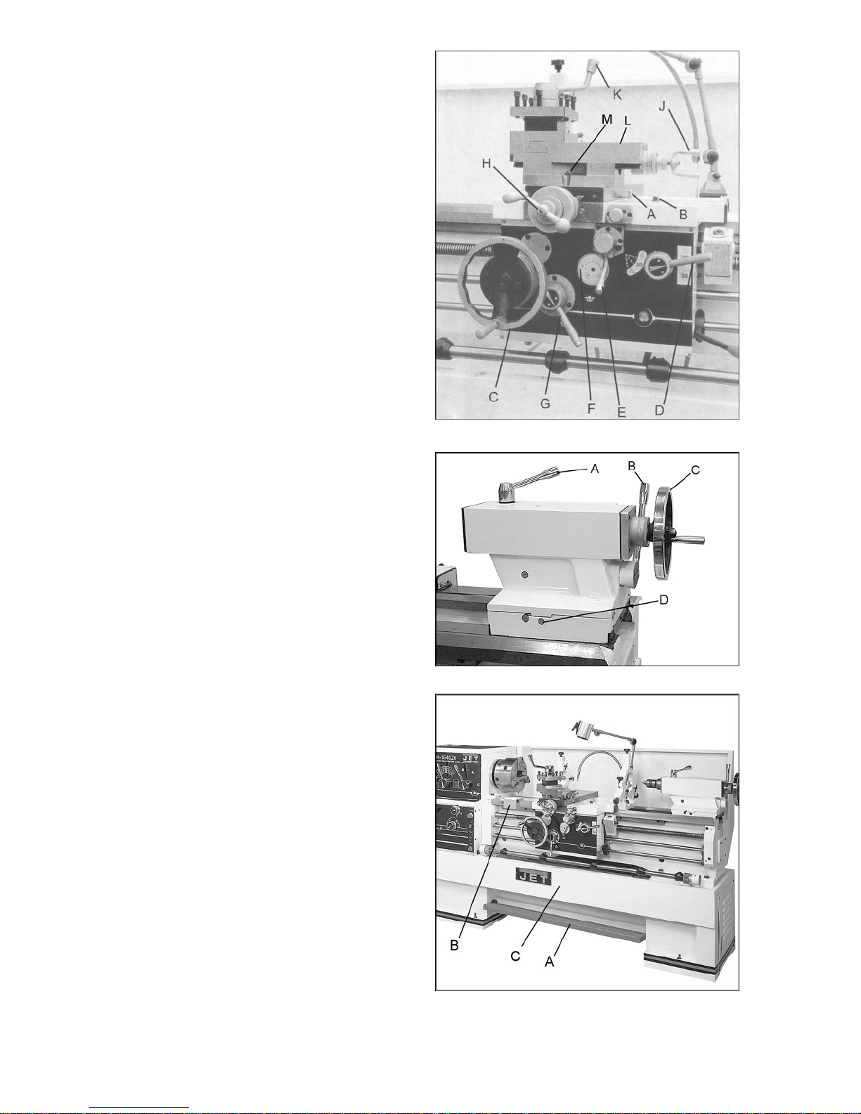
15. Compound Rest Traverse Handle (J,
Figure 13): Located on the end of the
compound slide. Rotate clockwise or
countercl oc k wise to posi tion.
16. Tool Post Cl amping Lever (K, Figure 13):
Located on top of the tool post. Rotate
countercl ockwise to l oosen and cloc kwise to
tighten.
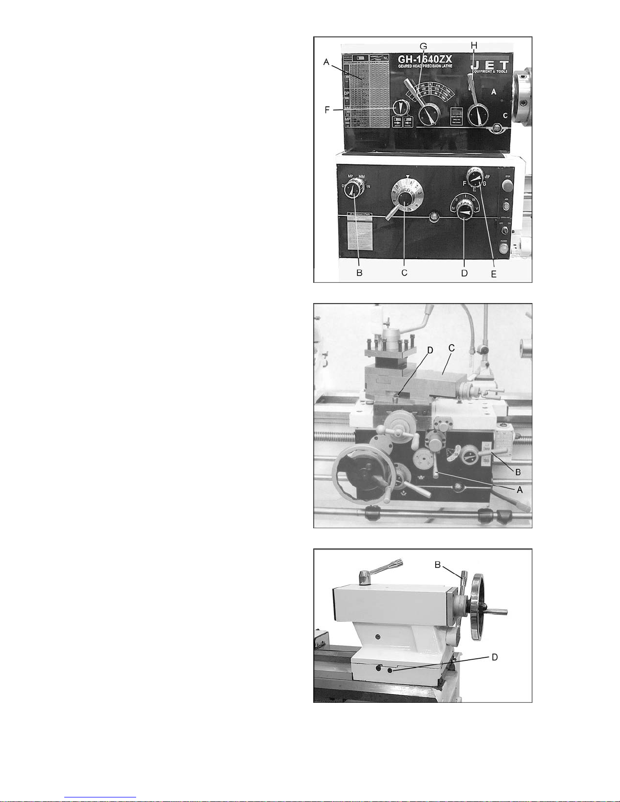
17. Tailstock Quill Clamping Lever (A, Figure
14): Located on the tailstock. Rotate
clockwise to lock the sleeve. Rotate
countercl oc k wise to unlock.
18. Tailstock Clamping Lever (B, Figure 14):
Lift up t o lock. Push down to unloc k. If the
tailstock has a heavy load, tighten the
hexagon head at right side of the tailstock
for auxiliary l oc ki ng.
19. Tailstock Quill Traverse Handwheel (C,
Figure 14): Rotat e cl ockwise to advance t he
quill and count erclockwise to retract it.
20. Tailstock Off-Set Adjustment (D, Figure
14): Two hex socket cap screws locat ed on
the tailstock base are used to off-set the
tailstock for cutting tapers. Loosening one
screw while tightening the other will off-set
the tailstock . Do not clam p the tailstock loc k
handle when adjusting.
Figure 13 (repeated)
21. Foot Brake (A, Figure 15): The connect ing
rod mechanism is in the bed stand. The
braking device is in the pulley of the
headstock. P ress the pedal to stop all lathe
functions. ( Caution: Lathe still has power.)
22. Micro Carriage S top ( B, Fi gure 15): can be
used during manual feed oper ation. The dial
can be turned for fi ne tuning the position of
the stop. The micro carriage stop can be
moved along t he bed by loosening the t wo
socket head cap screws underneath the
stop.
23. Bed Cover (C, Figure 15): can be easily
removed to clean out the stand.
Figure 14
Figure 15
18
Operation
Feed and Thread Selection
1. Ref erence the feed and t hread chart on the
front of the headstock ( A, Figure 16).
2. Move lev ers and knobs (B/C/D/E, Figure 16)
to the appropri ate position according to t he
feed and thread chart.
Thread Cutting
1. Set forward/reverse lever (F, Figure 16) to
desired direction.
2. Set selector levers (G/H, Figure 16) to
desired R.P.M. [On EVS models, use lever
H and the v ariable speed dial on the swiv el
control panel to select speed.]
3. Select desired t hread using l evers (B/ C/ D/E,
Figure 16).
4. Set selector lever (A, Figure 17) to correct
position (neutral).
5. Engage the half nut lev er (B, Figure 17) .
Figure 16
6. Make a test cut with scrap material and
check results before cutting regular m aterial.
Gib Adjustments
After a period of time, some of the moving
components may need to be adjusted due to
wear.
Saddle
Turn gib screws on either si de of the saddle at
the rear to adjust t he dr ag on the saddle.
Cross Slide
Turn gib screws in the f r ont and rear of the gib
to adjust the dr ag of the cross slide.
Compound Slide
Turn gib screws to adjust the drag of the
compound slide.
Tailstock Off-Set
Follow the procedure below to off-set the
tailstock t o cut shall ow tapers:
1. Loosen tailstock in position by lowering
locking handl e (B, Figure 18) and loosening
hexagon head eccentric shaft at back of
tailstock.
Figure 17
2. Alternately l oosen and t i ghten f r ont and rear
screws (D, Fi gure 18). Note: Front screw is
shown.
Figure 18
19
Removing Gap Section
1. To remov e the gap section, rem ove four hex
socket cap screws, and two hex cap bolts.
2. Tighten the hex nuts on the tapered
alignment pins to loosen the pins. Once
loosened, they can be r em ov ed.
3. Gap section can now be removed.
Installing Removable Gap Section
1. Clean the bottom and the ends of the gap
section thoroughly.
2. Set gap section in plac e and align the ends.
3. Loosen the nuts on the locating pins and
push down through the gap into the lathe
bed.
4. Replace four hex socket cap screws and
tighten alt ernately until all are snug.
Belt Replacement and Adjustment
1. Disconnect machine from power source.
2. Open end gear cover, remove lower rear
cover and lower side cover. This will expose
the motor and v-belts.
Figure 19
3. Loosen upp er hex nut ( A, Figure 19). P lace
scrap piece of wood under motor to act as
lever. Lift motor up and bloc k tem por arily.
4. Remove belts. Install new belts onto pulleys.
5. Lift up on motor and remove temporary
blocking.
6. Tension belts by loosening lower nut (B,
Figure 19) and tightening upper nut (A,
Figure 19) unt il light f inger pressure cau ses
approxim ately 3/4” deflection on each belt.
7. Install covers and connect lathe to the
power source.
Aligning Tailstock to Headstock
1. Fit a 12” ground steel bar bet ween centers
of the headstock and t ailstock (Figure 20).
2. Fit a dial indicator to the top slide and
traverse the cent er line of the bar.
3. If adjustment is needed, align the tailstock
using the off- set screws (D, Figure 21) until
the tailstoc k is ali gned.
Figure 20
Figure 21
20

Parts List
ZX Series Lathes
WALTER MEIER (Manufacturing) Inc.
427 New Sanford Road
LaVergne, Tennessee 37086 Part No. M-321910-1
Ph.: 800-274-6848 Revision H1 08/2010
www.waltermeier.com Copyright © 2010 Walter Meier (Manufacturing) Inc.

Table of Con tents
Table of Contents .................................................................................................................................... 2
Stand Assembly ................................................................................................................................... 3-5
Brake Assembly ................................................................................................................................... 6-7
Bed Assembly .................................................................................................................................... 8-10
Headstock Assembly I ...................................................................................................................... 11-13
Headstock Assembly II ..................................................................................................................... 14-16
Headstock Assembly III .................................................................................................................... 17-18
Headstock Assembly IV .................................................................................................................... 19-20
Change Gear Box Assembly I ........................................................................................................... 21-22
Change Gear Box Assembly II .......................................................................................................... 23-24
Quick Change Gear B ox I ................................................................................................................. 25-27
Quick Change Gear B ox II ................................................................................................................ 28-29
Quick Change Gear B ox III ............................................................................................................... 30-31
Apron Assembly I ............................................................................................................................. 32-34
Apron Assembly II ............................................................................................................................ 35-37
Apron Assembly III ........................................................................................................................... 38-39
Carriage Assembl y ........................................................................................................................... 40-42
Micro Carri age Stop A ssembly ............................................................................................................... 43
Carriage Stop Assembly ................................................................................................................... 44-45
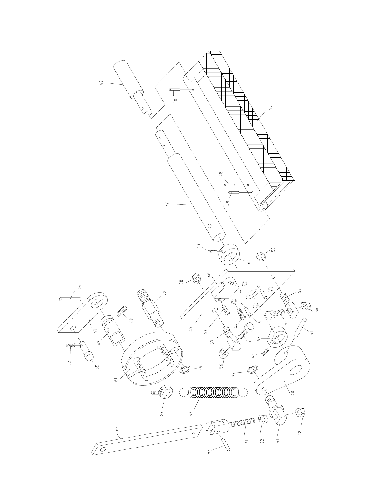
Four Way Tool Post .......................................................................................................................... 46-47
Tailstock Assembly I ......................................................................................................................... 48-49
Tailstock Assembly II ........................................................................................................................ 50-51
Steady Rest Assembly ...................................................................................................................... 52-53
Follow Rest Assembly ...................................................................................................................... 54-55
Coolant And Work Light Assembly .................................................................................................... 56-57
Other Parts ............................................................................................................................................ 58
Electrical Cabinet................................................................................................................................... 59
Wiring Diagram ...................................................................................................................................... 60
Rotary Switch Diagram .......................................................................................................................... 61
2
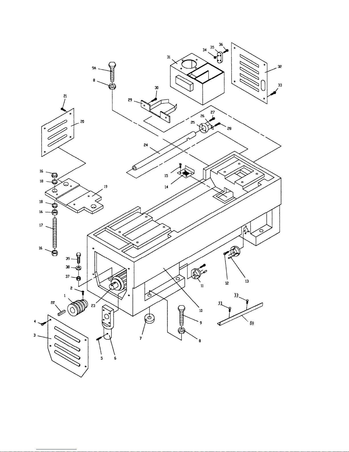
Stand Assembly
3

Stand Assembly
Index Part
No. No. Description Size Qty.
1 .......... ZX-01 101A ....................Pulley ................................................................................................... 1
............ GH2280ZX-01101 .........Pulley (for 2280ZX) ................................................................................ 1
2 .......... ZX-S2 ...........................Cylindrical End Set Screw ...................................M8x16 ........................ 1
3 .......... ZX-01734 ......................Cover .................................................................................................... 1
............ ML-2080-01701.............Cover (for 2280ZX) ................................................................................ 1
4 .......... ZX-S4 ...........................Cross Head Screw ..............................................M6x14 ........................ 4
5 .......... ZX-S2 ...........................Cylindrical End Set Screw ...................................M8x16 ........................ 1
6 .......... ZX-01701 ......................Pedal Rod Support ................................................................................ 1
............ ML-2080-01703.............Pedal Rod Support (for 2280ZX) ............................................................ 1
7 .......... ZX-01715 ......................Lining .................................................................................................... 6
8 .......... TS-1540231 ..................Hex Nut ..............................................................M24-2 ......................... 6
9 .......... ZX-01712 ......................Hex Cap Bolt ......................................................................................... 3
9A ....... ZX- 01713 ......................Hex Cap Bolt ......................................................................................... 3
10 ........ ZX-01102A ....................Bed Stand (for 40” models, serial # 010611ZX349 and lower) ................ 1
............ ZX-01 102AN .................New Bed Stand (for 40” models, serial # 010618Z X350 and hi gher ) ....... 1
............ ZX-01 102B ....................Bed Stand (for 60” models, serial # 010611ZX349 and lower) ................ 1
............ ZX-01 102BN .................New Bed Stand (for 60” models, serial # 010618ZX350 and higher) ...... 1
............ ZX-01 102C....................Bed Stand (for 1880ZX, serial # 010611ZX349 and lower) .................... 1
............ ZX-01 102CN .................New Bed Stand (for 1880ZX, serial # 010618ZX350 and higher ) ............ 1
............ GH2280ZX-01102 .........Bed Stand (for 2280ZX) ......................................................................... 1
11 ........ ZX-01703 ......................Fixed Support ........................................................................................ 2
12 ........ TS-150341 ....................Socket Head Cap Screw .....................................M6x14 ........................ 4
13 ........ ZX-S13 .........................Taper Pin ............................................................5x20 ........................... 2
14 ........ ZX-01705 ......................Water Leaking Chip Guard..................................................................... 1
15 ........ ZX-S15A .......................Cross Head Screw ..............................................M5x20 ........................ 4
16 ........ TS-1540121 ..................Hex Nut ..............................................................M20 ............................ 9
17 ........ ZX-01702 ......................Bolt........................................................................................................ 3
............ ML-2080-01704.............Bolt (for 2280ZX) ................................................................................... 3
18 ........ TS-1550111 ..................Fla t W a sher ........................................................M20 ............................ 6
19 ........ ZX-01122A ....................Motor Mounting Plate (for 14” models) ................................................... 1
............ ZX-01 122B ....................Motor Mounting Plate (for 16”/18” models) ............................................. 1
............ ML-2080-01122 .............Motor Mounting Plate (for 22” model) ) .................................................... 1
20 ........ ZX-01726 ......................Cover .................................................................................................... 1
............ GH2280ZX-01701 .........Cover .................................................................................................... 1
21 ........ ZX-S4 ...........................Cross Head Screw ..............................................M6x14 ........................ 4
22 ........ ZX-S22 .........................Key.....................................................................10x8x70 ..................... 1
23 ........ ZX-S23BC ....................Main Motor (for 22” model) .................................10 HP, 6P, 3Ph............ 1
............ ZX-S23A .......................Main Motor (for 14” models) ................................7.5HP, 4P, 3Ph............ 1
............ ZX-S23B .......................Main Motor (for 16”/18” models) ..........................7.5HP, 6P, 3Ph............ 1
24 ........ ZX-017609A..................Wire Conduit (for 1440/1640/1840Z X) .................................................... 1
............ ZX-017609B..................Wire Conduit (for 1460/1660/1860ZX) .................................................... 1
............ ZX-017609C .................Wire Conduit (for 1880/2280ZX) ............................................................ 1
25 ........ ZX-01708 ......................Wire Conduit Support ............................................................................ 1
26 ........ ZX-01706 ......................Locking Plate ......................................................................................... 1
27 ........ ZX-S27 .........................Cross Head Screw ..............................................M5x8 .......................... 2
28 ........ ZX-S15 .........................Cross Head Screw ..............................................M4x6 .......................... 1
29 ........ ZX-01711 ......................Water Reception Plate ........................................................................... 1
30 ........ ZX-S4 ...........................Cross Head Screw ..............................................M6x14 ........................ 2
31 ........ ZX-01510 ......................Coolant Tank ......................................................................................... 1
32 ........ ZX-01714 ......................Cover .................................................................................................... 1
............ ML-2080-01702.............Cover (for 2280ZX) ................................................................................ 1
33 ........ ZX-S4 ...........................Cross Head Screw ..............................................M6x14 ........................ 4
34 ........ ZX-S34 .........................Nut .....................................................................M3 .............................. 4
35 ........ ZX-S 35 .........................Co olant Indicator ................................................................................... 1
36 ........ ZX-S36 .........................Cross Head Screw ..............................................M3x20 ........................ 4
4

Index Part
No. No. Description Size Qty.
37 ........ TS-1540072 ..................Hex Nut ..............................................................M10 ............................ 4
38 ........ TS-1550071 ..................Fla t W a sher ........................................................M10 ............................ 4
39 ........ TS-1491041 ..................Hex Cap Bolt ......................................................M10x30 ...................... 4
80 ........ ZX-01716A ...................Stand Front Cover (for 1440/1640/1840ZX)............................................ 1
............ ZX-01716B ...................Stand Front Cover (for 1460/1660/1860ZX)............................................ 1
............ ZX-01716C ...................Stand Front Cov er (f or 1880/2280ZX) .................................................... 1
81 ........ ZX-01501 ......................Gasket................................................................................................... 1
82 ........ ZX-S82 .........................Hex Nut ..............................................................M5 .............................. 2
83 ........ ZX-01740 ......................Left Tra y ................................................................................................ 1
84 ........ ZX-01741 ......................Right Tr a y .............................................................................................. 1
85 ........ ZX-01511 ......................Gasket................................................................................................... 2
86 ........ ZX-S86 .........................Cross Head Screw ..............................................M5x16 ........................ 6
87 ........ ZX-01512 ......................Gasket................................................................................................... 1
88 ........ ZX-05753 ......................Extending Plate ..................................................................................... 1
............ JX21004 .......................Terminal Board (not shown) ................................................................... 1
............ 18301 ...........................Junction Box (not shown)....................................................................... 1
............ D97-4 ............................Plastic Fitting (not shown) ...................................................................... 1
5
Brake Assembly
6
 Loading...