

Jet Elite EGH-1880, Elite EGH-21120, Elite EGH-2180 Operating Instructions And Parts Manual
Operating Instructions and Parts Manual
1800 Series Lathe
Models: EGH-1880 | EGH-2180 | EGH-21120
®
JET
427 New Sanford Road
LaVergne, Tennessee 37086
www.jettools.com
Ph.: 855-336-4032
Part No. M-EGH-1880
REV D1 07/2015
Copyright © 2015 JET

1.0 WARRANTY AND SERVICE
JET® warrants every product it sells against manufacturers’ defects. If one of our tools needs service or repair, please
contact Technical Service by calling 1-855-336-4032, 8AM to 5PM CST, Monday through Friday.
WARRANTY PERIOD
The general warranty lasts for the time period specified in the literature included with your product or on the official JET
branded website, jettools.com.
WHO IS COVERED?
This warranty covers only the initial purchaser of the product from the date of delivery.
WHAT IS COVERED?
This warranty covers any defects in workmanship or materials subject to the limitations stated below. This warranty does not
cover failures due directly or indirectly to misuse, abuse, negligence or accidents, normal wear-and-tear, improper repair,
alterations or lack of maintenance.
HOW TO GET TECHNICAL SUPPORT
Please contact Technical Service by calling 1-855-336-4032. Please note that you will be asked to provide proof of initial
purchase when calling. If a product requires further inspection, the Technical Service representative will explain and assist
with any additional action needed. JET has Authorized Service Centers located throughout the United States. For the name
of an Authorized Service Center in your area call 1-855-336-4032 or use the Service Center Locator on the JET website.
2
1800 Series Lathe

MORE INFORMATION
JET® is constantly adding new products. For complete, up-to-date product information, check with your local distributor or
visit the JET website, jettools.com.
HOW STATE LAW APPLIES
This warranty gives you specific legal rights, subject to applicable state law.
LIMITATIONS ON THIS WARRANTY
JET LIMITS ALL IMPLIED WARRANTIES TO THE PERIOD OF THE LIMITED WARRANTY FOR EACH PRODUCT.
EXCEPT AS STATED HEREIN, ANY IMPLIED WARRANTIES OF MERCHANTABILITY AND FITNESS FOR A PARTICULAR
PURPOSE ARE EXCLUDED. SOME STATES DO NOT ALLOW LIMITATIONS ON HOW LONG AN IMPLIED WARRANTY
LASTS, SO THE ABOVE LIMITATION MAY NOT APPLY TO YOU.
JET SHALL IN NO EVENT BE LIABLE FOR DEATH, INJURIES TO PERSONS OR PROPERTY, OR FOR INCIDENTAL,
CONTINGENT, SPECIAL, OR CONSEQUENTIAL DAMAGES ARISING FROM THE USE OF OUR PRODUCTS. SOME
STATES DO NOT ALLOW THE EXCLUSION OR LIMITATION OF INCIDENTAL OR CONSEQUENTIAL DAMAGES, SO
THE ABOVE LIMITATION OR EXCLUSION MAY NOT APPLY TO YOU.
JET sells through distributors only. The specifications listed in JET printed materials and on official JET website are given as
general information and are not binding. JET reserves the right to effect at any time, without prior notice, those alterations
to parts, fittings, and accessory equipment which they may deem necessary for any reason whatsoever. JET® branded
products are not sold in Canada by JPW Industries, Inc.
NOTE: JET is a division of JPW Industries, Inc. References in this document to JET also apply to JPW Industries, Inc., or
any of its successors in interest to the JET brand.
EGH-1880 | EGH-2180 | EGH-21120
3

2.0 TABLE OF CONTENTS
1.0 WARRANTY AND SERVICE ..........................................................................................................................................2
2.0 TABLE OF CONTENTS ..................................................................................................................................................4
3.0 SAFETY PRECAUTIONS ...............................................................................................................................................5
4.0 INTRODUCTION ............................................................................................................................................................6
5.0 SPECIFICATIONS ..........................................................................................................................................................7
6.0 GENERAL INSTRUCTION .............................................................................................................................................8
6.1 GENERAL LAYOUT OF LATHE ..................................................................................................................................8
6.2 FOUNDATION PLAN .................................................................................................................................................9
7.0 INSTALLATION ............................................................................................................................................................ 11
7.1 LEVELING THE LATHE ...........................................................................................................................................11
7.2 CLEANING THE MACHINE .....................................................................................................................................12
7.3 LUBRICATION CHECKS .........................................................................................................................................12
7.4 CHUCK AND CHUCK MOUNTING (FOR D1-6 SPINDLE) .....................................................................................13
8.0 ELECTRICAL CONNECTIONS ....................................................................................................................................14
9.0 OPERATION .................................................................................................................................................................14
9.1 LATHE CONTROLS .................................................................................................................................................14
9.2 ELECTRICAL CONTROL PANEL ............................................................................................................................15
9.3 HEADSTOCK SELECTORS ....................................................................................................................................15
9.4 THREADS AND FEEDS ...........................................................................................................................................16
9.5 APRON CONTROLS ................................................................................................................................................16
9.6 THREADING DIAL INDICATOR ...............................................................................................................................17
9.7 CROSS SLIDE .........................................................................................................................................................17
9.8 TOP SLIDE ...............................................................................................................................................................18
9.9 TAILSTOCK ..............................................................................................................................................................19
9.10 END GEAR TRAIN .................................................................................................................................................19
9.11 DRIVING BELTS ....................................................................................................................................................19
9.12 LEADSCREW SHEAR PIN ....................................................................................................................................20
9.13 FEED TRIP ADJUSTMENT ....................................................................................................................................20
9.14 APRON HANDWHEEL ...........................................................................................................................................21
9.15 LIMIT SWITCHES ..................................................................................................................................................21
9.16 LATHE ALIGNMENT ..............................................................................................................................................21
9.17 GAP BRIDGE (FOR GAP BED TYPE LATHE) ......................................................................................................22
10.0 TROUBLE SHOOTING ..............................................................................................................................................23
11.0 LAYOUT OF ELECTRICAL BOX ................................................................................................................................24
12.0 RECOMMENDED CUTTING SPEED OF LATHE ......................................................................................................25
13.0 PARTS LISTS AND DIAGRAMS ................................................................................................................................25
14.0 WIRING DIAGRAM .....................................................................................................................................................90
4
1800 Series Lathe

3.0 SAFETY PRECAUTIONS
1. Read and understand the entire owner’s manual before attempting assembly or operation.
2. Read and understand the warnings posted on the machine and in this manual. Failure to comply with all of these
warnings may cause serious injury.
3. Replace the warning labels if they become obscured or removed.
4. This lathe is designed and intended for use by properly trained and experienced personnel only. If you are not familiar
with the proper and safe operation of a lathe, do not use until proper training and knowledge have been obtained.
5. Do not use this lathe for other than its intended use. If used for other purposes, JET
warranty and holds itself harmless from any injury that may result from that use.
6. Always wear approved safety glasses/face shields while using this lathe. Everyday eyeglasses only have impact
resistant lenses; they are not safety glasses.
7. Before operating this lathe, remove tie, rings, watches and other jewelry, and roll sleeves up past the elbows. Remove
all loose clothing and confine long hair. Non-slip footwear or anti-skid floor strips are recommended. Do not wear
gloves.
8. Wear ear protectors (plugs or muffs) during extended periods of operation.
9. Some dust created by power sanding, sawing, grinding, drilling and other construction activities contain chemicals
known to the state of California to cause cancer, birth defects or other reproductive harm. Some examples of these
chemicals are:
• Lead from lead based paint.
• Crystalline silica from bricks, cement and other masonry products.
• Arsenic and chromium from chemically treated lumber.
Your risk of exposure varies, depending on how often you do this type of work. To reduce your exposure to these
chemicals, work in a well-ventilated area and work with approved safety equipment, such as face or dust masks that
are specifically designed to filter out microscopic particles.
10. Do not operate this machine while tired or under the influence of drugs, alcohol or any medication.
11. Make certain the switch is in the OFF position before connecting the machine to the power supply.
12. Make certain the machine is properly grounded.
13. Make all machine adjustments or maintenance with the machine unplugged from the power source.
14. Remove adjusting keys and wrenches. Form a habit of checking to see that keys and adjusting wrenches are
removed from the machine before turning it on.
15. Keep safety guards in place at all times when the machine is in use. If removed for maintenance purposes, use
extreme caution and replace the guards immediately after maintenance is complete.
16. Check damaged parts. Before further use of the machine, a guard or other part that is damaged should be carefully
checked to determine that it will operate properly and perform its intended function. Check for alignment of moving
parts, binding of moving parts, breakage of parts, mounting and any other conditions that may affect its operation. A
guard or other part that is damaged should be properly repaired or replaced.
17. Do not use power tools in damp/wet locations or other dangerous environments. Do not expose them to rain. Keep
work area well lighted. Provide for adequate space surrounding work area and non-glare, overhead lighting.
18. Keep the floor around the machine clean and free of scrap material, oil and grease.
19. Keep visitors a safe distance from the work area. Keep children away.
20. Make your workshop child proof with padlocks, master switches or by removing starter keys.
21. Give your work undivided attention. Looking around, carrying on a conversation and “horse-play” are careless acts
that can result in serious injury.
22. Maintain a balanced stance at all times so that you do not fall or lean against moving parts. Do not overreach or use
excessive force to perform any machine operation. Never force the cutting action.
23. Do not operate the lathe in flammable or explosive environments. Do not use in a damp environment or expose to
rain.
®
, disclaims any real or implied
EGH-1880 | EGH-2180 | EGH-21120
5

24. Use the right tool at the correct speed and feed rate. Do not force a tool or attachment to do a job for which it was not
designed. The right tool will do the job better and more safely.
25. Use recommended accessories; improper accessories may be hazardous.
26. Maintain tools with care. Keep cutting tools sharp and clean for the best and safest performance. Follow instructions
for lubricating and changing accessories.
27. Do not attempt to adjust or remove tools during operation. Disconnect tools before servicing; when changing
accessories, such as blades, bits, cutters, and the like.
28. Never stop a rotating chuck or workpiece with your hands.
29. Choose a low spindle speed when working unbalanced workpieces, and for threading and tapping operations.
30. Do not exceed the maximum speed of the workholding device.
31. Do not exceed the clamping capacity of the chuck.
32. Secure Work. For safety and use of both hands, use clamps or a vise to hold work when practical.
33. Workpieces longer than 3 times the chucking diameter must be supported by the tailstock or a steady rest.
34. Avoid small chuck diameters with large turning diameters.
35. Avoid short chucking lengths and small chucking contact.
36. Turn off the machine and disconnect from power before cleaning. Use a brush to remove shavings or debris — do not
use your hands.
37. Do not stand on the machine. Serious injury could occur if the machine tips over.
38. Never leave the machine running unattended. Turn the power off and do not leave the machine until moving parts
come to a complete stop.
39. Remove loose items and unnecessary work pieces from the area before starting the machine.
40. Direction of feed — feed work into a blade or cutter against the direction of rotation of the blade or cutter only.
41. Installation work and electrical wiring must be done by qualified electrician in accordance with all applicable codes
and standards.
42. Tighten all locks before operating.
43. Rotate workpiece by hand before applying power.
44. Rough out workpiece before installing on faceplate.
45. Do not mount split workpiece or one containing knot.
46. Use lowest speed when starting new workpiece.
!
This means that if precautions are not heeded, it
may result in minor injury and/or possible machine
damage.
4.0 INTRODUCTION
This manual is provided by JET® covering the safe operation and maintenance procedures for a JET Model EGH1880/2180 and EGH-21120. This manual contains instructions on installation, safety precautions, general operating procedures, maintenance instructions and parts breakdown. Your machine has been designed and constructed to provide years
of trouble-free operation if used in accordance with the instructions as set forth in this document.
If there are questions or comments, please contact your local supplier or JET. JET can also be reached at our web site:
www.jettools.com. Retain this manual for future reference. If the machine transfers ownership, the manual should accompany it.
6
!
This means that if precautions are not heeded, it
may result in serious injury or possibly even death.
1800 Series Lathe

5.0 SPECIFICATIONS
MODEL EGH-1880 EGH-2180 EGH-21120
STOCK NUMBER 892200 892250 892270
CAPACITY
Swing over Bed 18-1/9 in. 21 in. 21 in.
Swing over Cross Slide 11 in. 14 in. 14 in.
Distance between Centers 80 in. 80 in. 120 in.
BED
Width of Bed 13-4/7 in. 13-4/7 in. 13-4/7 in.
Swing Through Gap 28 in. 31 in. 31 in.
Length of Gap 9-5/6 in. 9-5/6 in. 9-5/6 in.
HEADSTOCK
Spindle Mount D1-8
Spindle Bore 3-1/8 in.
Number of spindle speeds 16
Range of spindle speeds 20-1,600 R.P.M
Spindle Taper MT-7
CROSS SLIDE
Cross Slide Travel 10-2/3 in.
Top Slide Travel 5-2/5 in.
TAIL STOCK
Tailstock Spindle Travel 6-1/2 in.
Tailstock Diameter 3 in.
Taper in Tailstock Spindle MT-5
THREADS AND FEEDS
Longitudinal feeds (IPR) 0.0015-0.04”
Cross feeds (IPR) 0.00075-0.02”
Inch threads Number/Range (38) 2-72”
Metric threads Number/Range (40) 0.4-14mm
D.P. threads Number/Range (21) 8-44
M.P. threads Number/Range (18) 0.3-3.5
ELECTRICS
Motor
Coolant Pump Motor 1/8 HP
Overall Dimensions 139 x 44 x 69 in. 139 x 44 x 69 in. 182 x 44 x 69 in.
Machine Net Weight 5,953 lbs. 6,614 lbs. 8,157 lbs.
Gross Weight 6,835 lbs. 7,496 lbs. 9,920 lbs.
We reserve the right to modify and improve our products.
10 HP, 230/460V, 3-PH
Prewired 230V CSA/CUS Certified
EGH-1880 | EGH-2180 | EGH-21120
7
6.0 GENERAL INSTRUCTION
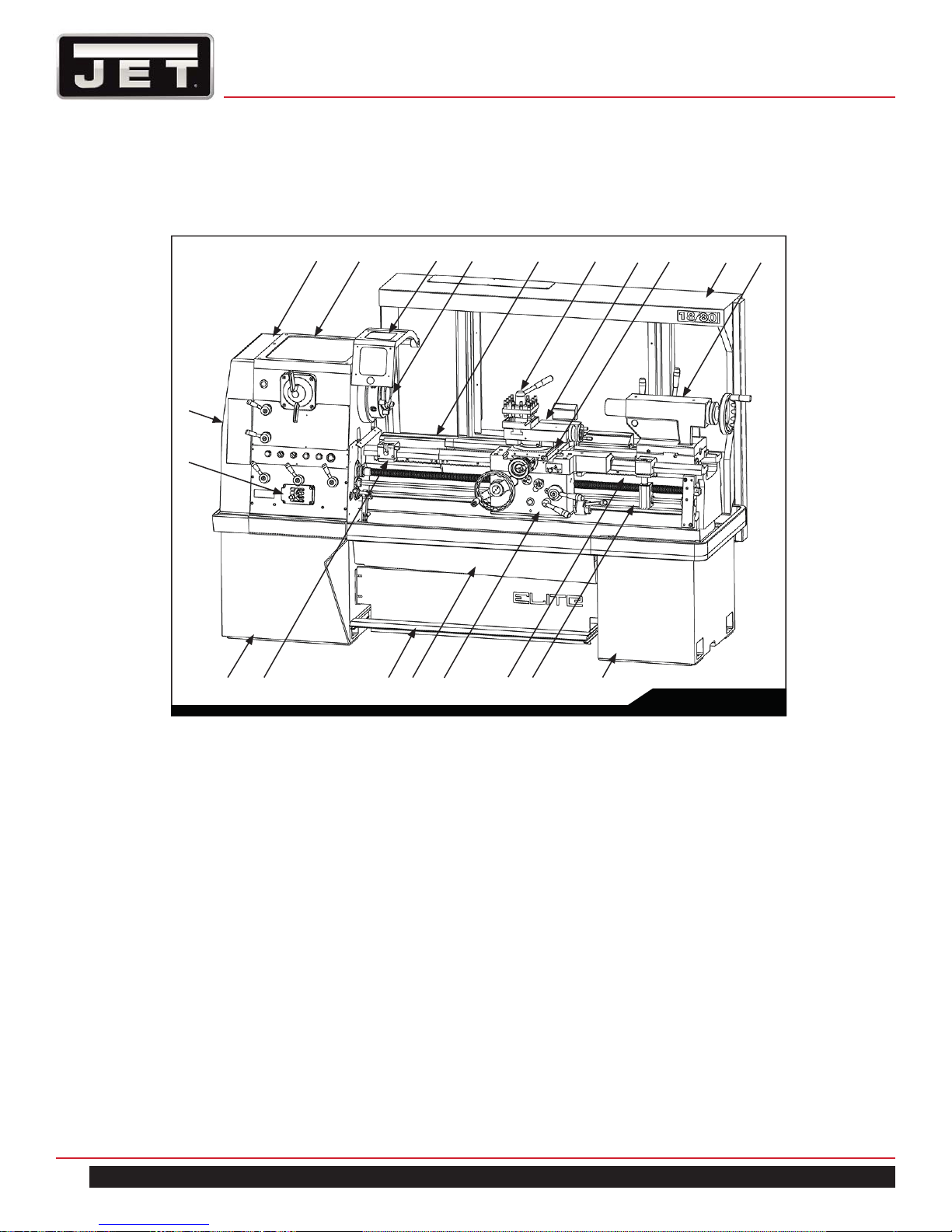
6.1 GENERAL LAYOUT OF LATHE
1
20
19
18
23 4 5 67 89
1011 121314151617
Fig. 1
1. Headstock
2. Chuck guard (optional)
3. Spindle
4. Bed
5. 4-Way tool post
6. Top slide
7. Saddle and Cross slide
8. Splash guard (optional)
9. Tailstock
12. Feed shaft
13. Apron
14. Front moveable chip tray
15. Footbrake
16. Carriage micro stop set (optional)
17. Head-end plinth
18. Gearbox
19. End Cover (gear train)
20. Electrical control
10. Tail-end plinth
11. Protection Cover for leadscrew (optional)
8
1800 Series Lathe
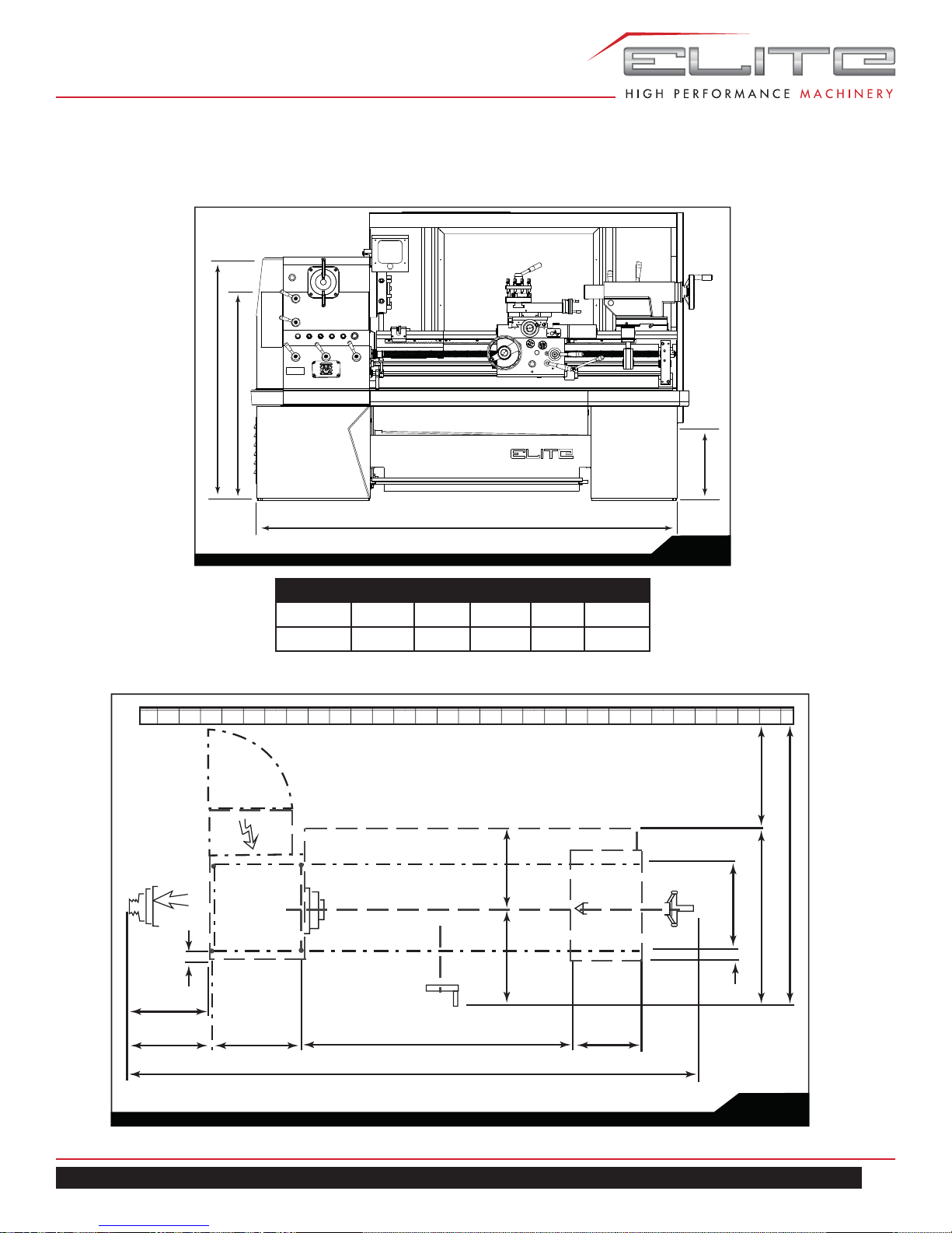
6.2 FOUNDATION PLAN
BC
BT
26.97”
FB
Fig. 2
Model LCY FB BC BT FW
EGH-1880 162.60" 88.58" 45.08" 53.54" 130.12"
EGH-2180 162.60" 88.58" 46.65" 54.72" 130.12"
2.76”
20.87”
21.65”
EGH-1880 | EGH-2180 | EGH-21120
LCY
FB
20.47”
24.21”
26.97”
71.65”
21.46”
44.69”
2.76”
16.93”22.83”
Fig. 3
9
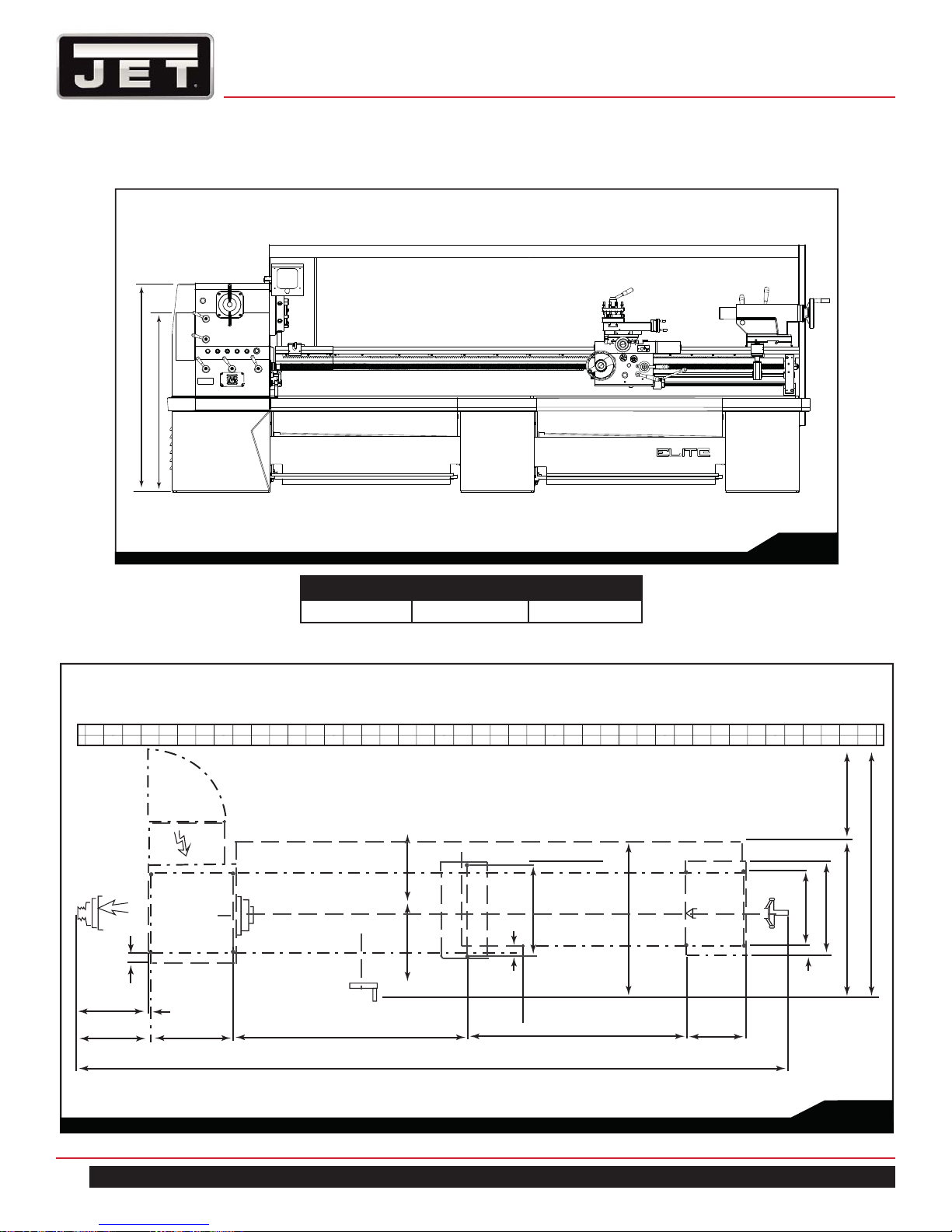
6.2 FOUNDATION PLAN
BC
BT
Fig. 4
Model BC BT
EGH-21120 46.65" 54.72"
2.76”
20.87”
21.65”
.79”
22.83”
10
65.28”
202.76”
2.17”
25.79”
63.51”
20.47”
24.21”
16.93”
26.97”
71.65”
26.97”
21.46”
44.69”
2.76”
Fig. 5
1800 Series Lathe
7.0 INSTALLATION
1. Finish removing all crate material from around lathe.
2. Unbolt lathe from shipping pallet.
3. Choose a location for the lathe that is dry and
has sufficient illumination (consult OSHA or ANSI
standards for recommended lighting levels in workshop
environments).
4. Allow enough room to service the lathe on all four
sides, and to load and off-load work pieces. In
addition, if bar work is to be performed, allow enough
space for stock to extend out the headstock end. If
used in production operations, leave enough space for
stacking unfinished and finished parts.
5. The foundation must be solid to support the weight of
the machine and prevent vibration, preferably a solid
concrete floor.
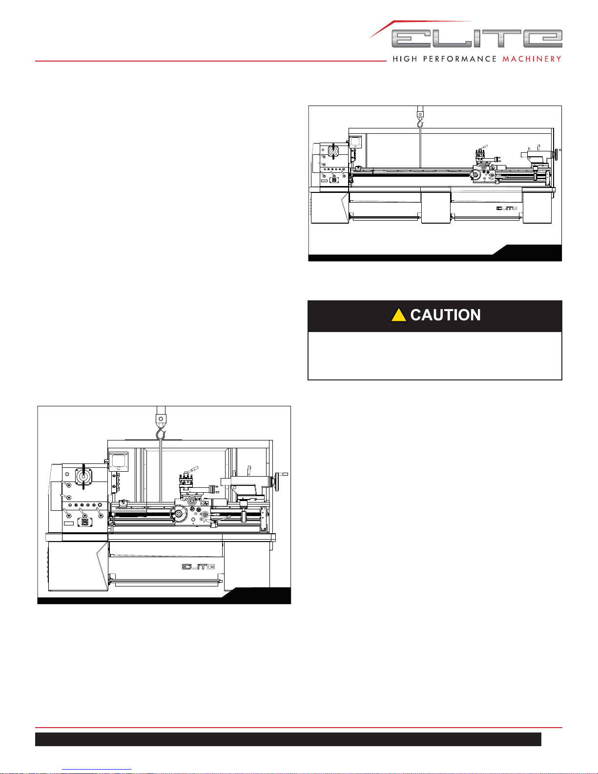
6. The lathe’s center of weight is near the headstock.
Before lifting, move the tailstock and the carriage to
the right end of the bed and lock them.
7. With properly rated lifting equipment, slowly raise lathe
off shipping pallet. (see Figure 6). Do not lift lathe by
the spindle.
Fig. 7
!
Confirm that all suspension equipment is properly
rated and in good condition for lifting lathe. Do not
allow anyone beneath or near load while lifting.
7.1 LEVELING THE LATHE
Fig.6
It is imperative that the lathe be on a level plane; that is,
where headstock and tailstock center points remain aligned
throughout the tailstock travel, with the bed ways absent of
twist and thus parallel to the operational center line.
A lathe which is not properly leveled will be inaccurate, producing tapered cuts. Also, the center point of the tailstock
will vary as it is positioned along the bed, thus requiring
constant readjustment.
9. Use a machinist’s precision level on the bed ways
both front to back and side to side, as shown in Figure
7. Take the reading in one direction every ten inches.
Make sure the ways are clean and free of any debris
before placing a level upon them.
10. Deviation over bed length (see Figure 8):
(a) Maximum 0.02/1000mm
(b) Maximum 0.04/1000mm
EGH-1880 | EGH-2180 | EGH-21120
11
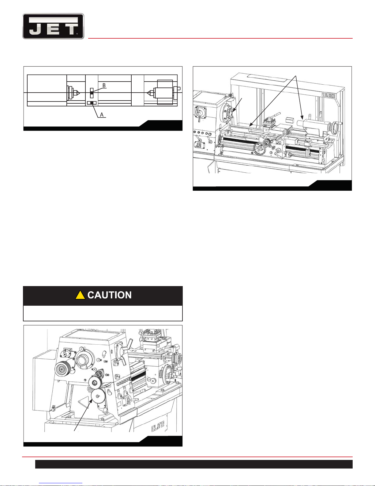
Fig. 8
11. Tighten foot screw nuts evenly to avoid distortion.
12. Leveling should be inspected occasionally, and especially if the accuracy of the lathe begins to diminish.
7.2 CLEANING THE MACHINE
*Notice items:
1. Before operating any controls, remove the anti-rust
coating on all slideways and other places.
2. When cleaning, use mineral spirits or kerosene,
instead of cellulose solvents, which may damage the
paint finish.
3. Oil all brightly machined surfaces immediately after
cleaning. Apply machine oil on slideway and heavy oil
or grease on the end gears.
4. It is recommended that all slideways, the leadscrew
and feedshaft are lightly cleaned (a bristle paint brush
is useful for this).
!
Do not use compressed air to clean the machine.
Bed way and quill
Spindle
Fig. 10
7.3 LUBRICATION CHECKS
Headstock/Gearbox/Carriage, Apron/T ailstock
Refer to Figure 11.
Before operating the machine, make the following important checks:
• The headstock is filled to correct level marked on oil
sight window with Shell Tellus oil 32 or equivalent.
Check oil weekly and change the oil every 6 months.
• The gearbox is filled to level marked on oil sight
window with Shell Tellus oil 68 or equivalent. Check
oil weekly and change the oil every year.
• The carriage apron is filled to level marked on oil
sight window with Shell Tellus oil 68 or equivalent.
Check oil weekly and change the oil every year.
• There are two oil balls on the tailstock and two oil
balls on the bracket.
• Add No.68 oil 3 c.c. to them respectively every day
before operating to ensure the smoothness of ways.
• There are three oil balls on the cross slide and top
slide.
• Add No.68 oil 10 c.c. to them respectively every day
before operating to ensure the smoothness of lead
screws.
A manually operated one-shot lubrication pump (A) is
incorporated into the apron, and draws oil from the apron
reservoir.
End gear train
12
Fig. 9
It enables the operator to ensure that the slideways are
kept adequately lubricated. The pump should be operated
before and occasionally during the work period.
1800 Series Lathe
3-Oil ball
Oil sight
Oil sight
Drain plug
Manual lubrication pump
Oil sight
Oil inlet
Oil cap
2-Oil ball
2-Oil ball
Hexagon socket head plug
Fig. 11
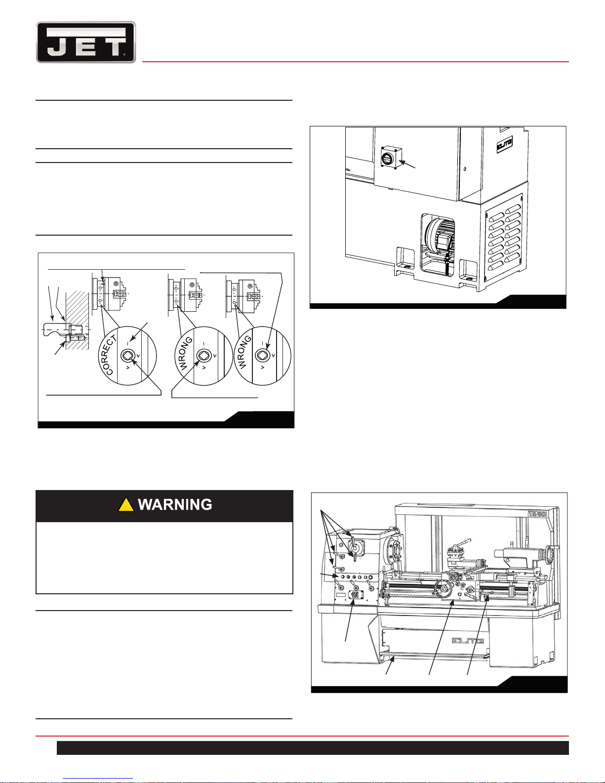
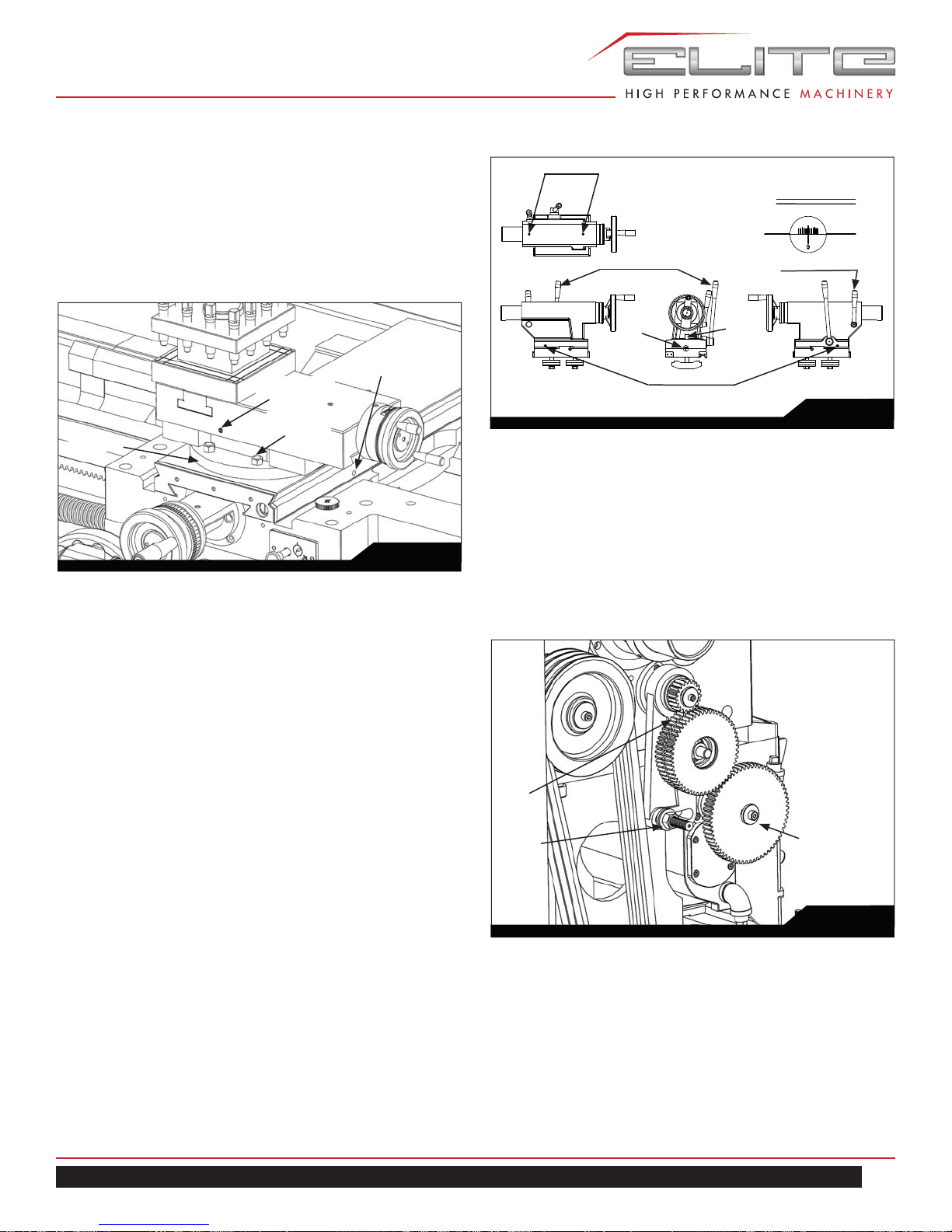
7.4 CHUCK AND CHUCK MOUNTING
(FOR D1-6 SPINDLE)
!
Use only high-speed chucks with these machines.
When fitting chucks or faceplate, ensure that spindle and
chuck tapers are thoroughly cleaned and that all cams lock
in the correct positions the first.
It may be necessary to re-set the camlock studs (A) when
mounting a new chuck. To do this, remove the hexagon
socket locking screws (B) and set each stud so that the
EGH-1880 | EGH-2180 | EGH-21120
scribed ring (C) is flush with the rear face of the chuck with the slot - lining up with the locking screw hold.
Now mount the chuck or faceplate on the spindle nose and
tighten the six cams in turn.
When fully tightened, the cam lock line on each cam
should be between the two V marks on the spindle nose.
If any of the cams do not tighten fully within these limit
marks, remove the chuck or faceplate and readjust the
stud as indicated in the illustration.
Fit and tighten the locking screw (B) at each stud before
remounting the chuck for work. A reference mark should
be made on each correctly fitted chuck or faceplate to
coincide with the reference scribed on the spindle nose.
This will assist subsequent remounting.
13
Note: Do not interchange chucks or faceplates
between lathes without checking for correct cam
lock.
Make sure the lathe is properly grounded.
Note: Take careful note of speed limitations when
using faceplates; 12 inch faceplates should not
be run at speeds higher than 1000 rev/min. and 14
inch faceplates should not be run at speeds higher
than 770 rev/min.
Reference mark on spindle nose and chuck
A
C
Cam release datum
B
Detail of camlock stud
ass’y
Cam lock line between arrows
Turn stud out one turn
Turn stud in one turn
Fig. 12
8.0 ELECTRICAL CONNECTIONS
Confirm that power available at the lathe’s location is the
same rating as the lathe.
Main Switch
Fig. 13
9.0 OPERATION
9.1 LATHE CONTROLS
A. Headstock selector
B. Electrical control
C. Gearbox (threads and feeds)
D. Apron control units, for surfacing, sliding and
threading controls.
E. Spindle rotation, forward, stop and reverse.
F. Footbrake.
!
Electrical connections must be made by a qualified electrician in compliance with all relevant
codes. This machine must be properly grounded
while in use to help protect the operator from electrical shock and possible fatal injury.
IMPORTANT: The lathe must be wired properly
and phased correctly. The spindle should rotate
counterclockwise (as viewed from the tailstock
end) while the feed rod rotates clockwise (as
viewed from the tailstock end). If the phasing
needs correction, disconnect lathe from power
source and switch any two of the three power
leads (not the green ground wire).
14
A
B
C
FDE
Fig. 14
1800 Series Lathe
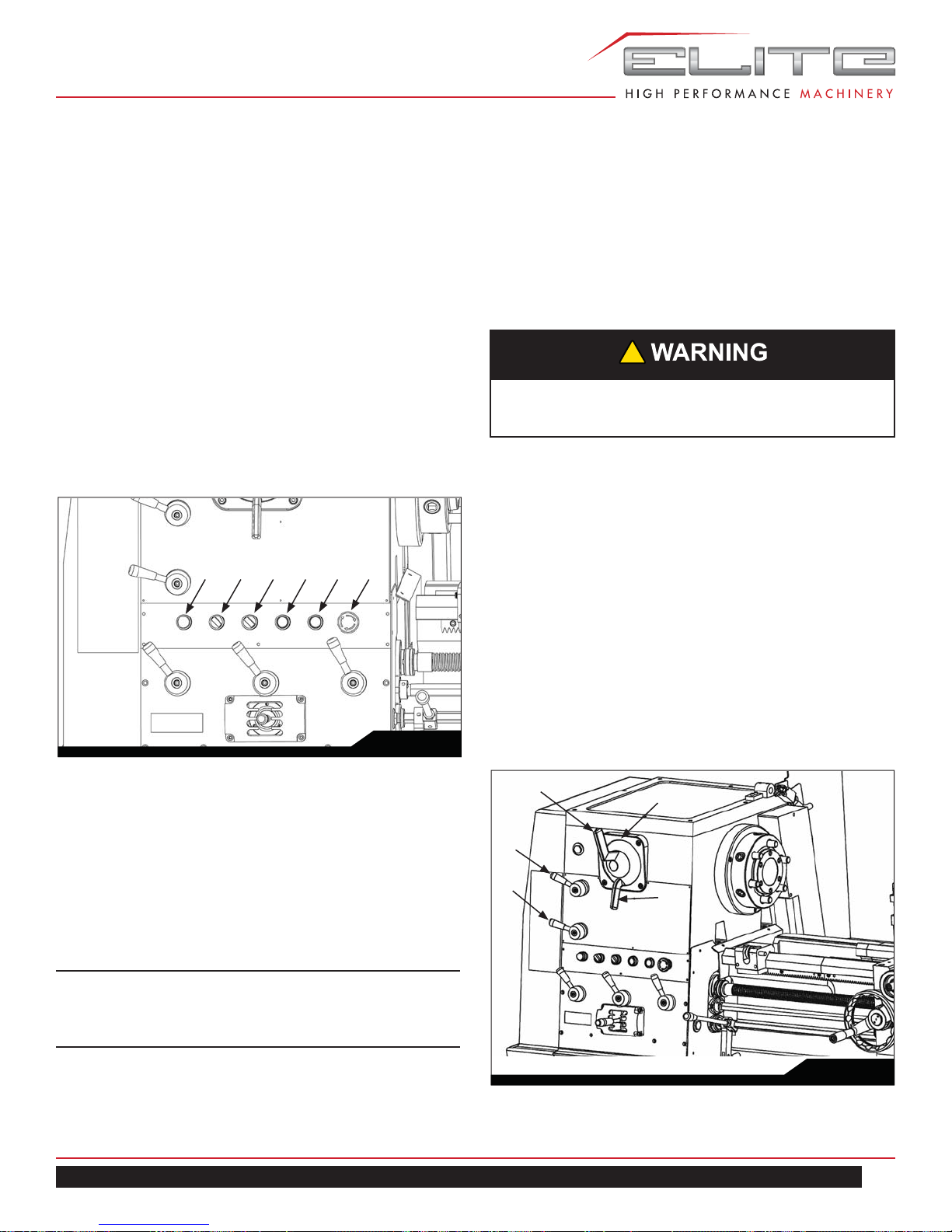
9.2 ELECTRICAL CONTROL PANEL
With the exception of the lathe isolator, all electrical controls are fitted onto the front face of the headstock.
1. POWER INDICATOR LIGHT: When the power is on,
the indicator light glows.
2. WORK LAMP: On/Off switch.
3. COOLANT PUMP: On/Off switch.
4. Press the red mushroom-head button to stop
the main motor and also electrical supply to auxillary
services.
5. Press the green button to start the main drive motor.
The indicator lamp glows while the motor is running.
6. EMERGENCY STOP SWITCH: press in order to kill
all electric power to lathe.
165432
Fig. 15
H-L selector for gearbox (H4)
1.
Following each feed rate or thread pitch on gearbox
thread and feed chart, there is a prefix of either H or
L.
2. Move H-L selector to H or L accordingly for feeding
or threading. If this lever is positioned at “–”, the
headstock rotation will not be transmitted to gearbox.
!
In High position do not exceed spindle speed of 350
R.P.M.
Apron orientation selector (H5)
1. This selector may affect the rotation orientation of
lead screw, feed rod and therefore the movement
direction of apron.
2. Forward (left-hand arrow) is used for cutting righthand threads. Reverse (right-hand arrow) is used for
cutting left-hand threads.
Headstock selectors
H1: Four colors correspond to 16 speeds.
H2: Four kinds of colors.
H3: Four kinds of color arrow points.
H4: Low-High selector for gearbox.
H5: Apron orientation selector.
9.3 HEADSTOCK SELECTORS
Spindle speed selector (H1, H2, H3)
1. The sixteen available speeds are shown on the lever
- operated dial (H1) in four groups, each of which is
further divided into four displayed spindle speeds.
To select your speed, rotate the outer dial until the
desired speed aligns with its corresponding color on
the plate that is affixed to the machine. Then turn
inner dial until the same color of arrow aligns with the
desired speed.
Note: Do not select speeds while spindle is
rotating or clutch is engaged - apron control must
be central (disengaged) to avoid gear damage.
To free the spindle for hand rotation, set any one of the
blank spaces on the outer dial to the mid-point of the plate
that is affixed to machine (H2).
EGH-1880 | EGH-2180 | EGH-21120
H5
H4
H3
H2
H1
Fig. 16
15
9.4 THREADS AND FEEDS
Gearbox, thread and feed selectors
All the thread pitches and feeds directly available from the
gearbox are shown on the data plate fitted on the front of
headstock and the positioning control levers are (G1), (G2),
(G3), and (G4).
End gear trains diagram
The end gear train should be arranged as in the
diagram shown on the dataplate (G5) to meet threading
requirements.
(G4) W–Z five section selector
(G5) End gear train diagram
G1
G2
G5
G4
Feeds:
Sliding feeds per spindle revolution range from 0.0015 to
0.04 inch (0.04mm to 1.0mm).
Surfacing feeds per spindle revolution range from 0.00075
to 0.02 inch (0.02 to 0.5mm).
Threads & Feeds
Imperial threads:
Kinds / Range
Metric threads: 40 Kinds / 0.4–14mm
Diametral pitch (D.P.)
worm gear
Module pitch (M.P.)
worm gear
Longitudinal feeds
Cross feeds
Gearbox Selectors
(G1) A,B,C three section selector
(G2) R,S,T three section selector
(G3) 1–8 eight section selector
38 Kinds / 2–72 T.P.I.
21 Kinds / 8–44 D.P.
18 Kinds / 0.3–3.5 M.P.
0.04–1.0mm
(0.0015"–0.04")
0.02–0.5mm
(0.00075"–0.02")
G3
Fig. 18
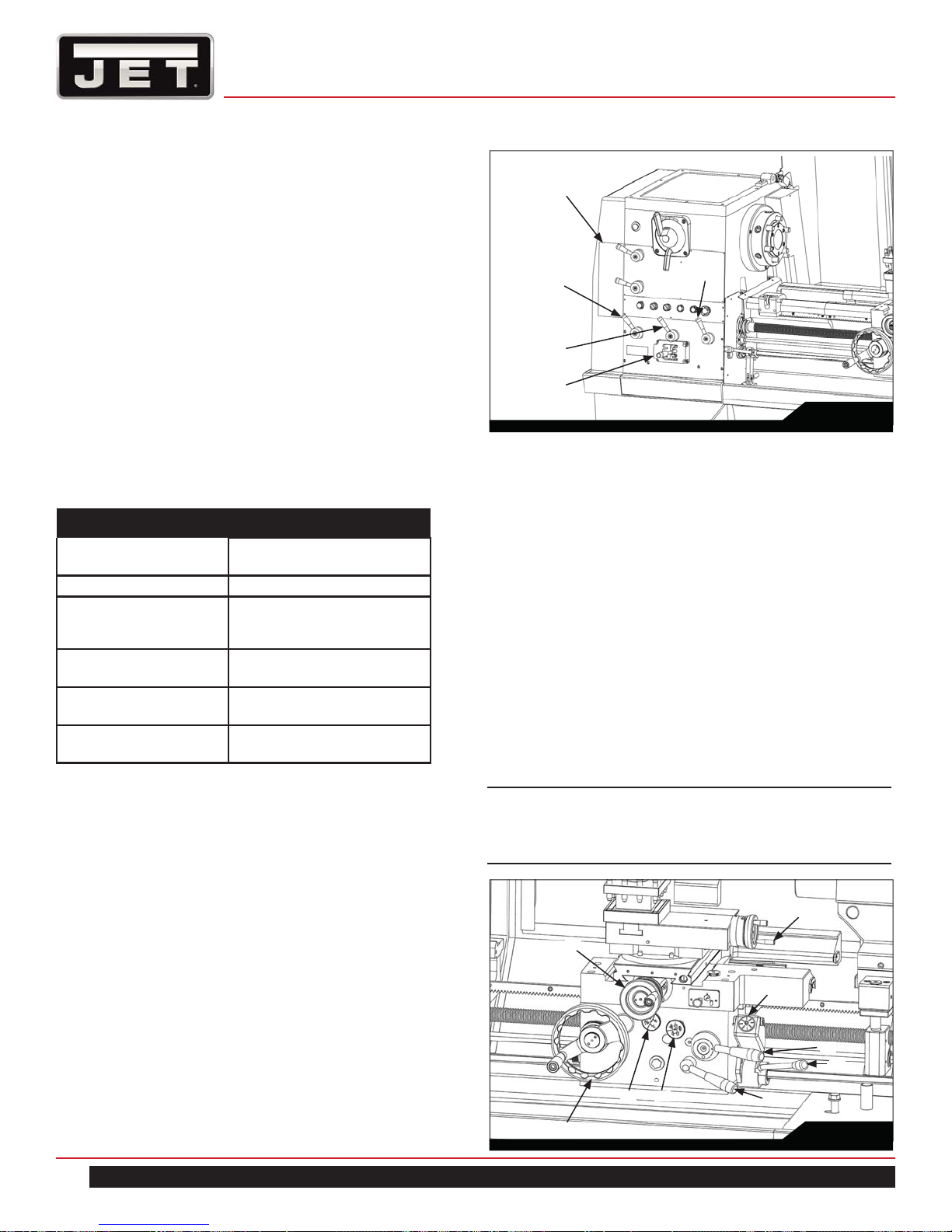
9.5 APRON CONTROLS
In addition to handwheel traverse the carriage can be power-operated through controls on the front of the apron.
(OL) Lever is moved down for power operation and up
for manual operation.
(A1) Push-pull knob selects power surfacing (cross feed)
when pulled out, sliding feeds are selected when the
knob is pushed in.
(A2) The adjacent push pull knob controls forward or
backward feed direction.
(A3) Lever is pressed downward to engage the lead-
screw nut for thread cutting. To avoid undue wear,
release the nut except when thread cutting. An interlock within the apron prevents inadvertent engagement of levers OL and A3 at the same time.
Note: Do not use headstock lever for reversing
feeds except during left-hand thread cutting; Use
instead, the apron handle (A2).
(A4) Carriage handwheel
(A5) Cross slide handwheel\
(A6) Compound rest handwheel
A5
(A7) Threading dial indicator
(A8) Spindle rotation, forward, stop and reverse: The
forward and reverse rotation of spindle is operated
by starting lever at right side of apron and controlled
by limit switches on the right-side the bedway.
A6
A7
A3
OL
16
A4
A1
A2
A8
Fig. 19
1800 Series Lathe
9.6 THREADING DIAL INDICATOR
For thread cutting:
• Tighten the handnut in order to maintain engagement
when engaging the indicator with the leadscrew.
When not required, release hand-nut and swing indicator to disengage.
• To cut even number threads per inch, the leadscrew
nut can be closed as any line on the dial aligns with
the datum mark.
• To cut odd number threads per inch, close the leadscrew nut at any NUMBERED line.
• Fractional threads of 1/2 or 1/4 T.P.I. may be cut by
closing the nut at the SAME NUMBERED LINE on
each pass of the tool.
• This dial can not be used with an IMPERIAL leadscrew to cut metric threads, D.P., M.P. which are
shown on gear box data plate. For the threads being
shown, the leadscrew nut must be kept closed. Use
apron control lever after each thread cutting when
the tool is withdrawn to original start of thread cutting
operation.
Multi-start threads can be cut on a lathe in three ways:
1. By repositioning the compound (top) slide one pitch
forward for each start. Note that the slide is normally
set at 90º to the axis of the machine cross-slide. The
accuracy of this method depends upon the skill of
the operator.
2. By using an accurately divided driver plate and
turning the work-piece one division forward for each
start.
3. By advancing the driver gear a calculated number
of turns to advance the spindle by one pitch of the
thread to be cut. The accuracy of this method is that
of the machine.
• With all series lathes, two ratios exist between the
spindle and driver gear shift, i.e. the LOW range
where the ratio is 1:2 and the HIGH range where
the ratio is 2:1
• In order to use this method, the number of teeth
on the driver gear must be divisible by the number
of starts being cut. The driver gear is then advanced by half this number of teeth when in LOW
range. And conversely, by twice the number of
teeth when in HIGH range.
• On the standard end gear train for this machine
the driver gear has 24 teeth; so that two, three or
four start threads, can readily be cut. For other
odd numbers of start a choice must be made of
methods 1 or 2.
Gear 24T for Imperial leadscrew
(Gear 28T/22T for Metric leadscrew)
End Gear Train
Fig. 20
Threading dial indicator
Handnut
Fig. 21
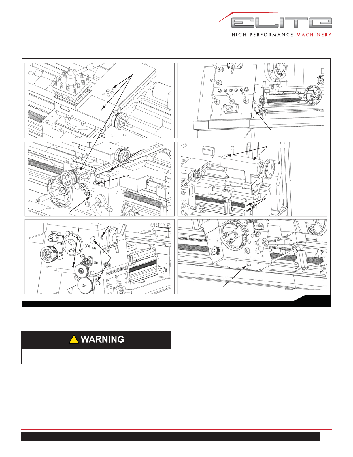
9.7 CROSS SLIDE
Cross slide nut adjusting:
• Reduce backlash by loosening rear hexagon socket
head bolt (M6) in top of cross slide, then carefully
screw in center set screw (S6) to adjust a wedge
within the split nut.
• Make only small adjustments at a time and retighten
two bolts (M6) before operating the cross slide several times by hand to be sure of smooth operation
throughout full travel.
EGH-1880 | EGH-2180 | EGH-21120
17
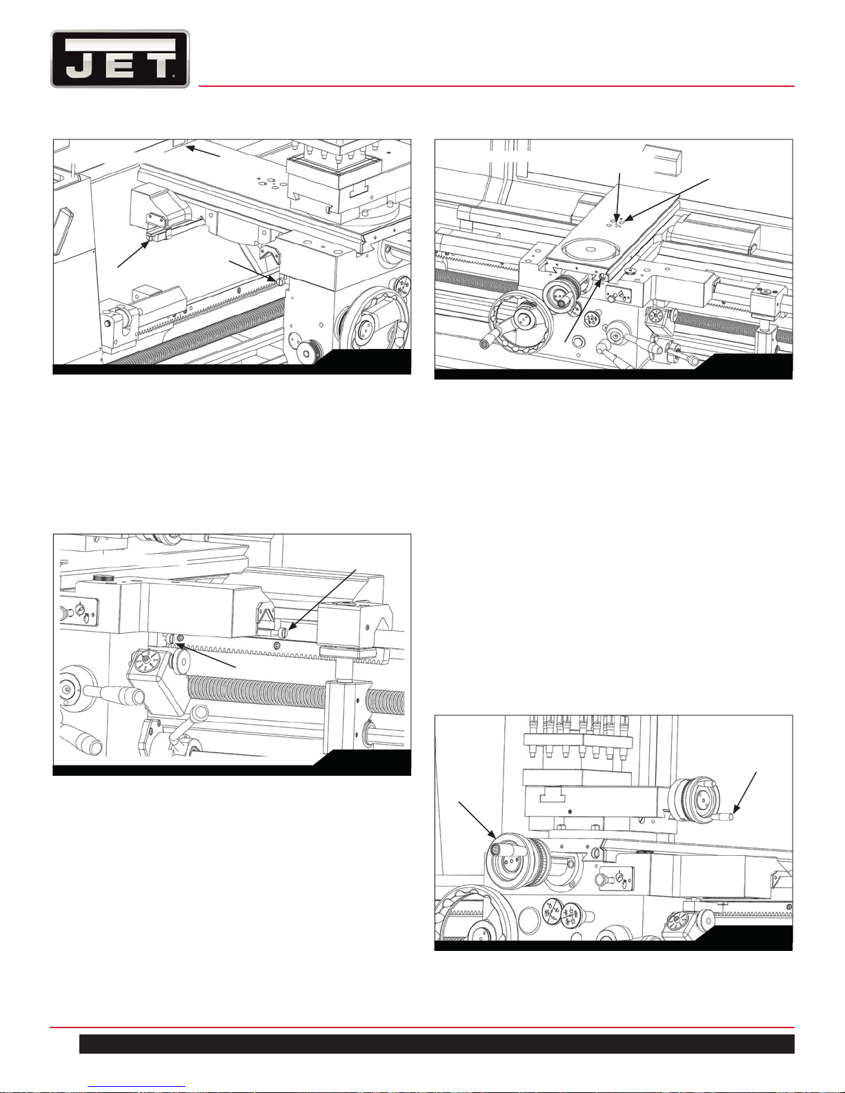
Bedway removed for clarity
R6
Turret removed for clarity
S6
by 3mm allen wrench
M6
by 6mm allen wrench
R3
F1
Fig. 22
Saddle and Cross slide gibs adjusting:
• Tapered gib strip is fitted to the slideways of saddle
cross-slide and top (compound) slides so that any
slack which may develop can be diminished. Check
and adjust them every six months.
• Ensure that slideways are thoroughly cleaned and
lubricated before attempting adjustment.
Bedway removed for clarity
F2
R4
F5
Fig. 24
9.8 TOP SLIDE
A solid topslide is fitted as standard equipment to the
cross-slide mounted on a swivel base which is marked
0-90-0-90º for accurate indexing.
(A5) Cross slide handwheel
(A6) Compound rest handwheel
Handwheel dials are graduated in inch or metric divisions
to suit the operation. (Dual dials supply imperial system
screw only)
Top slide gibs adjusting:
• You should regularly check and adjust them every six
months.
• Ensure that slideways are thorougly cleaned and
lubricated before attempting adjustment.
According to the following steps:
1. Use flat head screw driver to loosen the adjust screw
(F1) and (R4)/(R6) about 1/2 turn CCW.
2. Appropriately tighten adjust screw (F2) and (R3)/(F5)
about 1/2 turn CW.
3. Move saddle left and right to ensure smoothness.
4. Move cross slide forward and backward to ensure
smoothness.
18
Fig. 23
A6
A5
Fig. 25
1800 Series Lathe
According to the following steps:
1. Use a flat head screw driver to loosen the adjust
screw (P1), about 1/2 turn CCW.
2. Apropriately tighten adjust screw (P2), about 1/2
turn CCW.
3. Move top slide left and right to satisfy smoothness.
2-Oil ball
Clamp lever (A)
Detail of mark D
Clamp lever (C)
Set screw
by 4mm allen wrench
Hexagon nut
by 17mm spanner
Swivel base
P2
Fig. 26
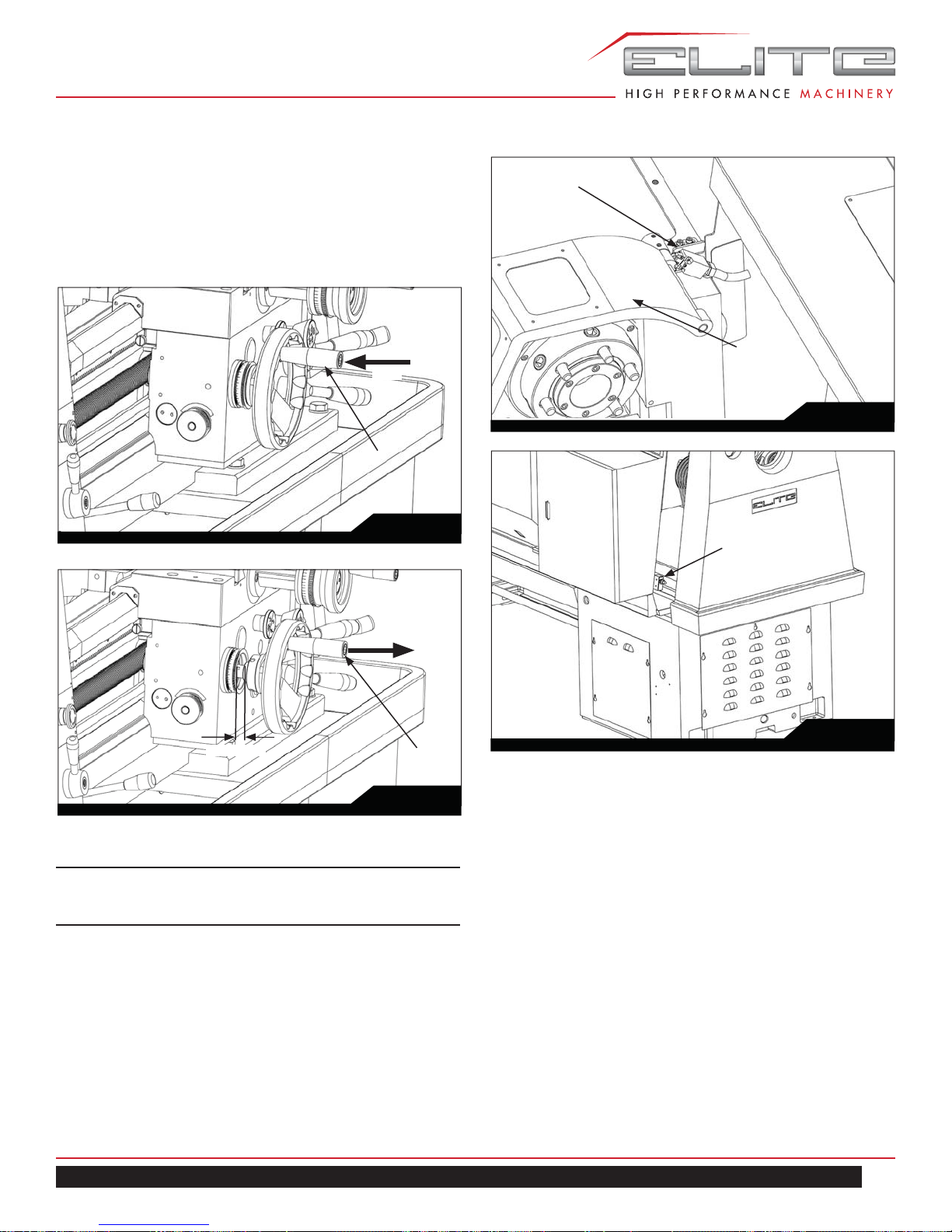
9.9 TAILSTOCK
Operation:
1. The tailstock can be freed for movement along the
bed by unlocking the clamp lever (A).
2. Additional clamping may be obtained by tightening
the large nut (B) located in a recess below the handwheel.
3. Release this clamping lever (A) before attempting to
move the tailstock or after there is no longer a need
for the additional clamping force.
4. The tailstock quill can be locked by lever (C).
Adjustment/Realignment
• The tailstock also can be offset for turning shallow
tapers or for realignment.
• Release the clamping lever (A) and adjust screw (S) at
each side of the base to move tailstock laterally across
the base.
• An indication of the offset is given by the datum
mark (D) at the tailstock end face, as picture shows.
• Tighten clamp lever after adjusting offset.
D
Adjust screw (S)
by 6mm allen wrench
B
Fig. 27
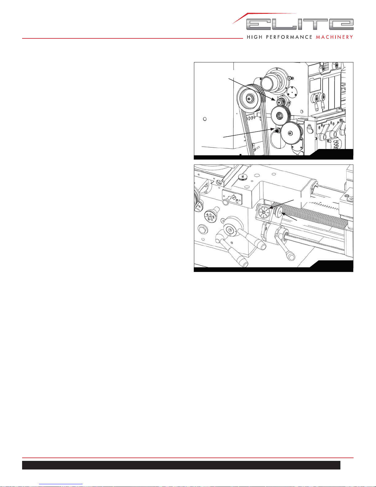
9.10 END GEAR TRAIN
1. Drive from headstock to gear box is transmitted
through a gear train enclosed by the headstock end
guard. Intermediate gears are carried on an adjustable swing-frame (M).
2. Gears must be thoroughly cleaned before fitting and
backlash must be maintained at 0.005” (0.127mm)
for correct meshing.
3. Lubricate gear regularly with thick oil or grease.
M
Hexagon
nut
(by 22mm
spanner)
Hexagon socket head bolt
(by 10mm allen wrench)
Fig. 28
9.11 DRIVING BELTS
1. To modify belt tension, remove the cover plate on
back of the headstock and adjust the screws (X) on
the hinged motor platform.
2. Ensure that the motor is correctly aligned with the
lathe axis.
3. Apply light finger pressure at a point midway between
motor and headstock pulleys, the resulting depression will be about 3/4" (19mm) when under tension.
EGH-1880 | EGH-2180 | EGH-21120
19
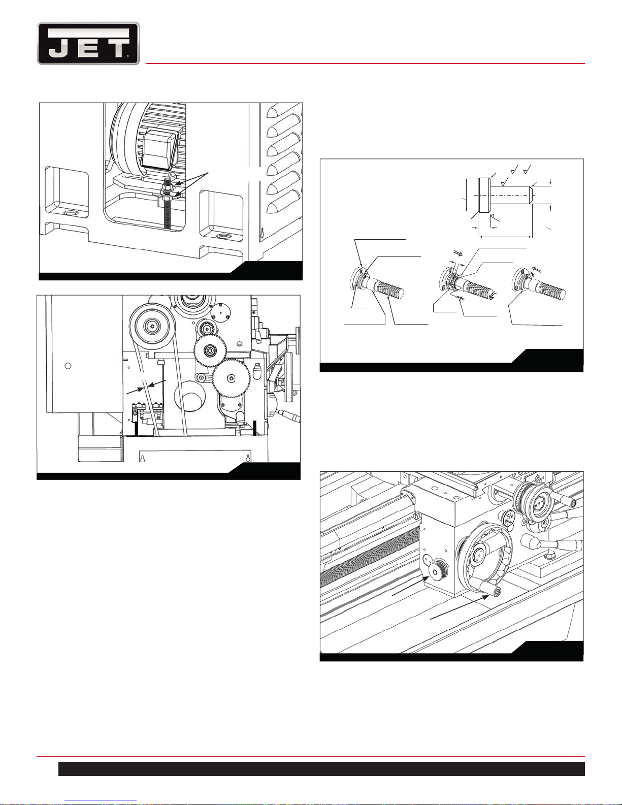
X:Hexagon nuts
(by 24mm spanner)
Fig. 29
5. Align the holes in flanged-shaft, collar and shroud
washer, then insert a new pin and turn the shroud
washer half circle towards the left to the collar with
snap ring to retain the new shear pin.
3.2
6.3
)
(
C0.2
Flanged bearing
30020
Flanged shaft
30016
1.8-0.1
Get space
o5.8
C0.2
0
3.2
3.2
10.5
Shroud washer
63008
Snap ring
S32
C0.5
–0.05
–0.1
o3.9
3/4” (19mm)
Fig. 30
9.12 LEADSCREW SHEAR PIN
Safety feature:
The transmission is protected against severe overload by
a shear pin fitted into the leadscrew drive, just beside the
right hand of the gearbox.
To replace a shear pin:
1. First disengage drive to the leadscrew by setting the
right-hand lever of the gearbox to the position W or X.
2. Move the shroud washer with snap ring right-ward to
the spring cover.
3. Then rotate the leadscrew by hand carrying the broken pin to the frontview, on same level to the slot of
flanged bearing.
4. With a magnetic screw driver, remove the broken
pin head from the collar, and other broken pin from
gearbox housing slot hole.
Slot
Spring cover
63006
BEFORE REPAIR
Leadscrew
630033-*0
Collar
63009
NEW
Shear pin
63010
REPAIR PROCESS
Shroud washer
63008
FINISHED
Fig. 31
9.13 FEED TRIP ADJUSTMENT
A trip mechanism is incorporated into the apron, enabling
saddle and/or cross-slide to be fed up to fixed stops.
Trip loads can be set high (+) or low (-) by adjustment of
the knurled handwheel (A9) on the side of the apron.
A9
A4
Fig. 32
20
1800 Series Lathe
9.14 APRON HANDWHEEL
The apron handwheel (A4) may be disengaged from its
gear train during power operation or when thread cutting,
by pulling the handwheel outwards to another spring-ball
detent.
Push
A4
Chuck guard limit switch
Chuck guard
Fig. 35
Fig. 33
Clearance
Fig. 34
Note: This does not apply when the longitudinal
power feed accessory is fitted.
9.15 LIMIT SWITCHES
Safety interlock:
• If the end cover is not closed, then the spindle and
coolant pump will not operate.
End cover limit switch
Fig. 36
A4
9.16 LATHE ALIGNMENT
With the lathe installed and running we recommend verification on machine alignment before beginning work.
Check machine level and alignment at regular periods to
ensure continued lathe accuracy.
Headstock check:
1. Take a light cut with a cutting tool over a 6” (152mm)
length of 2" diameter (50mm) steel bar gripped in the
chuck but not supported at the free end.
2. Micrometer readings at each end of the turned
length (at A and B) should be the same.
3. To correct a difference in readings, loosen the four
headstock hold-down screws (I) behind headstock
and (J) under the headstock, then adjust the offset
adjusting screws (K).
4. After adjustment, tighten screws (I)/(J) first and then
screw (K).
EGH-1880 | EGH-2180 | EGH-21120
21
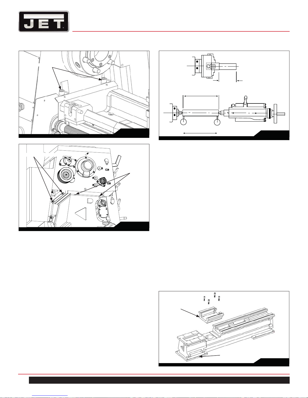
5. Repeat the test-cut and micrometer reading sequence until micrometer readings are identical.
(J) 2-Hex socket head bolts
12”
A
B
6”
Fig. 37
(K) 2-Adjusting Screws
(I) 2-Fixing screws
Fig. 38
Tailstock check:
1. Using a 12" (305mm) ground steel bar fitted between
headstock and tailstock centers, check the alignment
by fitting a dial-test indicator to the toolpost and traversing the center line of the bar.
2. To correct error, release the tailstock clamp lever and
adjust the offset screws provided.
3. Continue with checking and correction until alignment is perfect.
Fig. 39
9.17 GAP BRIDGE (FOR GAP BED TYPE LATHE)
• When removing the gap bridge from bedway, be
very careful in loosening the four fixing bolts and lift
the gap until guiding taper pins separate from bedway completely.
• When loosening the fixing bolts and separating the
taper pin, every particular precaution should be
made to prevent any damage to fixing bolts and
taper pins.
• The taper pins should be left in the gap portion after
removal of the gap bridge.
• Removed gap bridge must be stored in a very clean
and safe place with every precaution made against
damage and rust.
• The taper pins should be greased so as to make it
easy to reset the gap bridge with optimum original
accuracy.
• Be careful not to have dirt or chips entering into taper pin holes, holes for fixing bolts, or on the surface
where gap bridge is to be reset.
• Always keep the gap bridge clean.
22
Gap bridge
Bed
Fig. 40
1800 Series Lathe

10.0 TROUBLE SHOOTING
Trouble or Failure Possible Causes Correction
1 The electricity is on, but the spindle
does not run after the starting lever
is moved downward or upward
2 Outflow of coolant fluid is weak 1. Running orientation of coolant
3 No coolant fluid comes out of coolant
nozzle
4 Spindle does not stop instantly even
when treadle is fully depressed.
Sharp, shriek noise in braking action
5 Intermittent noise in headstock Headstock shift levers are not in
6 Headstock and gear train are
running and starting lever is moved
upward or downward, but the feed
rod or leadscrew does not rotate
7 When turning long workpiece the
right end is smaller than the left end
in diameter
1. Fuse is burned
2. Thermal relay is overloaded
pump is wrong
2. The inside of coolant pipe is rusted
or otherwise restricted
The steel ball inside the coolant pipe
is stuck to the “O” ring
Brake lining has been worn out Replace brake lining
position
Gearbox shift levers are not in
position
Tailstock is not in good alignment to
headstock
1. Replace fuse
2. Reset thermal relay
1. Interchange any two line of 3
phase line
2. Clear the pipe by compressed air
or rigid steel rod
Separate the steel ball from “O” ring
by compressed air
Gearbox shift levers are not in
position
Shift levers to correct positions as
specified on data plate
Offset tailstock until the center line
between headstock is parallel to
carriage movement
8 Chatter line occurs on turned
workpiece
9 No oil comes out of one shot
lubrication
10 Carriage vibrates during heavy
cutting
11 Oil leaks at right side of gearbox The lubricant in gearbox is too light Replace with slightly denser lubricant
1. Lathe cutter is dull
2. Bearing is too loose
Too much air is caught in oil groove Keep on pushing one shot lubrication
Gib is too loose in fitting Adjust screw in cross slide to drive
1. Sharpen the cutting angles of lathe
cutter
2. Adjust the tightness of nut.
pump until all air is driven out
the gib slightly inside
in gearbox
EGH-1880 | EGH-2180 | EGH-21120
23
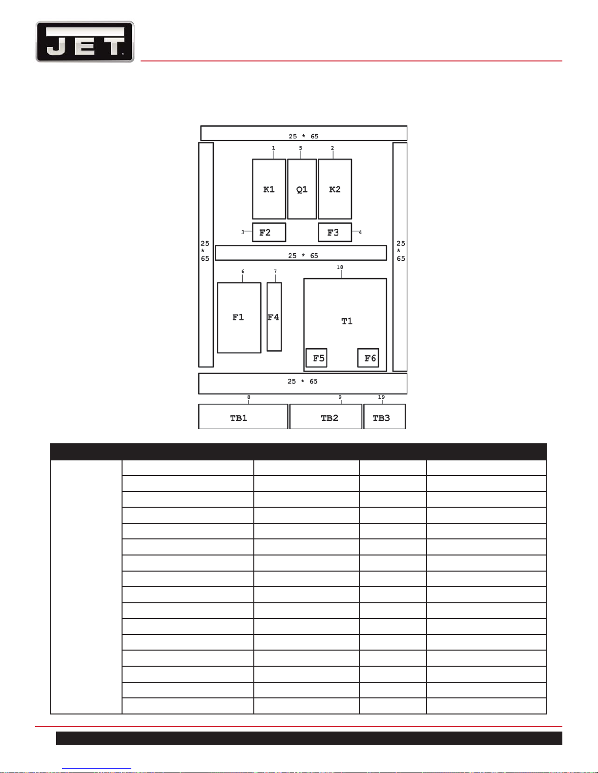
11.0 LAYOUT OF ELECTRICAL BOX
MODEL DESCRIPTION SPECIFICATION QUANTITY SYMBOL
1880
AC 220V
10HP
AC MAGNETIC SWITCH TENLC1D326B7 1 K1
AC MAGNETIC SWITCH TENLC1D096B7 1 K2
OVER RELAY TENLR3D356 1 F2
OVER RELAY TENLR3D036 1 F3
MAIN FUSE BASE TFU-303 3P50A 1 F1
FUSE BASE TFBR-102 2P10A 1 F4, F5
MICRO SWITCH TM-1307 1 LS1
E-STOP ALEPB-22-1B 1 E-STOP
SPINDLE MOTOR STOP APB-22-1B-R 1 SPB1
SPINDLE MOTOR RUN NFLPB-1A-30V-G 1 PB1
COOLANT STOP APB-22-1B-R 1 SPB2
COOLANT RUN NFLPB-1A-30V-G 1 PB2
POWER LAMP ALPL-22-30V-W 1 POWER LAMP
TRANSFORMER 140VA 1 T1
TERMINAL BOARD TB-25A-6P 1 TB1
TERMINAL BOARD TB-15A-12P 1 TB2
24
1800 Series Lathe

12.0 RECOMMENDED CUTTING
SPEED OF LATHE
13.0 REPLACEMENT PARTS —
EGH–1880, 2180, 21120
Workpiece material Speed (sfm) Feed (lpr)
Aluminum 2021 to 6061 500 0.002
Brass 75 0.001
Bronze 70 0.001
Cast Iron Gray 35 to 125 0.0015 to 0.004
Ductile 15 to 125 0.001 to 0.004
Malleable 35 to 170 0.0015 to 0.003
Copper 101 to 757 85 to 90 0.002
834 to 978 340 0.003
Magnesium AZ, AM, EZ,
ZE, HK types
Nickel Nickel 200 to
230
Monel 15 to 60 0.001 to 0.0015
Inconel,
Waspaloy
Hastelloy 10 to 15 0.002
Plastic TFE, CTFE 250 0.002
Nylon 350 0.002 to 0.003
Phenolic 350 0.003
Stainless Steel 201 to 385 65 to 85 0.001 to 0.0015
405 to 446 90 0.0011
15-5 PH, 16-6
PH, 14-4 PH
Steel 1005 to 1029 80 to 140 0.001 to 0.002
1030 to 1055 35 to 115 0.0009 to
1060 to 1095 30 to 80 0.0007 to 0.001
10L45 to
10L50
12L13 to
12L15
41L30 to
41L50
4140 to 4150 20 to 115 0.0007 to
4140 (35
HRC)
8617 to 8622 40 to 120 0.001 to 0.0016
M-1 to M-6 60 0.0013
H-10 to H-19 20 to 80 0.007 to 0.0011
D-2 to D-7 45 to 60 0.001
A-2 to A-9, 01
to 07
W-1, W-2 110 0.0015
M-50, 52100 20 to 85 0.0007 to
Titanium TI-6AI-6V 45 0.001
500 0.002
85 0.002
15 0.002
30 to 60 0.0006 to
0.0012
0.0015
40 to 140 0.0009 to
0.0015
225 to 280 0.003 to 0.0035
20 to 110 0.0007 to
0.0015
0.0015
70 0.001
45 to 60 0.001
0.0015
Replacement parts are listed on the following pages.
To order parts or reach our service department, call
1-855-336-4032, Monday through Friday (see our
website for business hours, www.jettools.com). Having
the Model Number and Serial Number of your machine
available when you call will allow us to serve you quickly
and accurately.
®
JET
427 New Sanford Road
LaVergne, Tennessee 37086
www.jettools.com
Phone: 855-336-4032
EGH-1880 | EGH-2180 | EGH-21120
25
HEADSTOCK ASSEMBLY 1
80
50
32
49
29
34
42
41
38
45
48
44
43
40
52
8
32
37
29
31
46
47
45
39
29
33
33
32
32
35
36
34
29
10
9
8
6
5
2
1
69
22
21
4
3
23
7
25
24
13
83
12
11
26
16
15
14
28
13
14
27
18
17
1
69
30
20
19
5
3
2
29
81
51
82
12
9
8
6
4
11
10
7
82
81
26
1800 Series Lathe
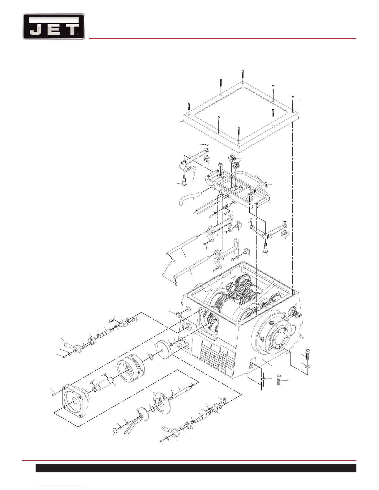
HEADSTOCK ASSEMBLY 1
62
61
55
57
53
56
54
69
58
59
EGH-1880 | EGH-2180 | EGH-21120
77
66
65
63
60
69
65
74
67
64
75
76
72
71
71
68
70
73
27

HEADSTOCK ASSEMBLY 1 – PARTS LIST
(16 SECTIONS HAVE CLUTCHES)
Index No. Part No. Description Size Qty.
1 EGH1880-1-A01 Washer 2
2 EGH1880-1-A02 Hub & Handle 2
3 TS-1502061 Hex. Socket Head Bolt CAP 5x25 4
4 EGH1880-1-A04 Collar 2
5 EGH1880-1-A05 S Key 4x4x15 2
6 EGH1880-1-A06 Shaft 2
7 EGH1880-1-A07 Key 4x4x20 2
8 EGH1880-1-A08 Pin 4
9 EGH1880-1-A09 Spring 2
10 EGH1880-1-A10 Shift Levers 2
11 EGH1880-1-A11 Snap Ring S18 2
12 EGH1880-1-A12 Change Speed Claw 2
13 EGH1880-1-A13 Flat Cross Screw 6x20 2
14 EGH1880-1-A14 Washer 2
15 EGH1880-1-A15 Speed Selector 1
16 EGH1880-1-A16 Snap Ring S30 1
17 EGH1880-1-A17 Speed Selector 1
18 EGH1880-1-A18 Key 5x5x14 1
19 EGH1880-1-A19 Cam Shaft 1
20 EGH1880-1-A20 S Key 5x5x14 1
21 TS-1504071 Hex. Socket Head Bolt CAP 8x35 4
22 EGH1880-1-A22 Cam Cover 1
23 EGH1880-1-A23 Key 7x7x18 2
24 EGH1880-1-A24 Cam Shaft 1
25 EGH1880-1-A25 Cam 1
26 EGH1880-1-A26 Snap Ring S35 1
27 EGH1880-1-A27 Cam 1
28 EGH1880-1-A28 Oil Sight 1
29 EGH1880-1-A29 Pin 6
30 EGH1880-1-A30 Rod 1
31 EGH1880-1-A31 Lever 1
32 EGH1880-1-A32 Snap Ring E10 4
33 EGH1880-1-A33 Change Speed Claw 2
34 EGH1880-1-A34 Bolt 2
35 EGH1880-1-A35 Lever 1
36 EGH1880-1-A36 Change Speed Claw 1
37 EGH1880-1-A37 Lever 1
38 EGH1880-1-A38 Rod 1
39 TS-1503071 Hex. Socket Head Bolt CAP 6x30 2
40 EGH1880-1-A40 Bracket 1
41 EGH1880-1-A41 Rod 2
42 EGH1880-1-A42 Nylon Tube & Spring Assembly 1
28
1800 Series Lathe
 Loading...