


OWNER'S MANUAL
JWBS-20 Woodworking Bandsaw
JET EQUIPMENT & TOOLS, INC. |
P.O. BOX 1349 |
Phone: 253-351-6000 |
A WMH Company |
Auburn, WA 98071-1349 |
Fax: 1-800-274-6840 |
www.jettools.com |
e-mail jet@jettools.com |
M-708752 11/01 |

This manual has been prepared for the owner and operators of a JET JWBS-20 Woodworking Bandsaw. Its purpose, aside from machine operation, is to promote safety through the use of accepted correct operating and maintenance procedures. Completely read the safety and maintenance instructions before operating or servicing the machine. To obtain maximum life and efficiency from your Bandsaw, and to aid in using the machine safely, read this manual thoroughly and follow instructions carefully.
Warranty & Service
The JET Group warrants every product it sells. If one of our tools needs service or repair, one of our Authorized Repair Stations located throughout the United States can give you quick service.
In most cases, any one of these JET Group Repair Stations can authorize warranty repair, assist you in obtaining parts, or perform routine maintenance and major repair on your JET, Performax or Powermatic tools.
For the name of an Authorized Repair Station in your area, please call 1-800-274-6848.
More Information
Remember, the JET Group is consistently adding new products to the line. For complete, up-to-date product information, check with your local JET Group distributor.
JET Group Warranty
The JET Group (including Performax and Powermatic brands) makes every effort to assure that its products meet high quality and durability standards and warrants to the original retail consumer/purchaser of our products that each product be free from defects in materials and workmanship as follow: 1 YEAR LIMITED WARRANTY ON ALL PRODUCTS UNLESS SPECIFIED OTHERWISE. This Warranty does not apply to defects due directly or indirectly to misuse, abuse, negligence or accidents, normal wear-and-tear, repair or alterations outside our facilities, or to a lack of maintenance.
THE JET GROUP LIMITS ALL IMPLIED WARRANTIES TO THE PERIOD SPECIFIED ABOVE, FROM THE DATE THE PRODUCT WAS PURCHASED AT RETAIL. EXCEPT AS STATED HEREIN, ANY IMPLIED WARRANTIES OR MERCHANTIBILITY AND FITNESS ARE EXCLUDED. SOME STATES DO NOT ALLOW LIMITATIONS ON HOW LONG THE IMPLIED WARRANTY LASTS, SO THE ABOVE LIMITATION MAY NOT APPLY TO YOU. THE JET GROUP SHALL IN NO EVENT BE LIABLE FOR DEATH, INJURIES TO PERSONS OR PROPERTY, OR FOR INCIDENTAL, CONTINGENT, SPECIAL, OR CONSEQUENTIAL DAMAGES ARISING FROM THE USE OF OUR PRODUCTS. SOME STATES DO NOT ALLOW THE EXLUSION OR LIMITATION OF INCIDENTAL OR CONSEQUENTIAL DAMAGES, SO THE ABOVE LIMITATION OR EXCLUSION MAY NOT APPLY TO YOU.
To take advantage of this warranty, the product or part must be returned for examination, postage prepaid, to an Authorized Repair Station designated by our office. Proof of purchase date and an explanation of the complaint must accompany the merchandise. If our inspection discloses a defect, we will either repair or replace the product, or refund the purchase price if we cannot readily and quickly provide a repair or replacement, if you are willing to accept a refund. We will return repaired product or replacement at JET’S expense, but if it is determined there is no defect, or that the defect resulted from causes not within the scope of JET’S warranty, then the user must bear the cost of storing and returning the product. This warranty gives you specific legal rights; you may also have other rights which vary from state to state.
The JET Group sells through distributors only. Members of the JET Group reserve the right to effect at any time, without prior notice, those alterations to parts, fittings, and accessory equipment which they may deem necessary for any reason whatsoever.
2
WARNING
1.Read and understand the entire instruction manual before attempting assembly or operation.
2.This band saw is designed and intended for use by properly trained and experienced personnel only. If you are not familiar with the proper and safe operation of a bandsaw, do not use until proper training and knowledge have been obtained.
3.Always wear approved safety glasses/face shields while using this machine.
4.Make certain the machine is properly grounded.
5.Before operating the machine, remove tie, rings, watches, other jewelry, and roll up sleeves above the elbow. Remove all loose clothing and confine long hair. Do not wear gloves.
6.Keep the floor around the machine clean and free of scrap material, oil and grease.
7.Keep the machine guards in place at all times when the machine is in use. If removed for maintenance purposes, use extreme caution and replace the guards immediately.
8.Do not over reach. Maintain a balanced stance at all times so that you do not fall or lean against blades or other moving parts.
9.Make all machine adjustments or maintenance with the machine unplugged from the power source.
10.Use the right tool. Don’t force a tool or attachment to do a job which it was not designed for.
11.Replace warning labels if they become obscured or removed.
12.Make certain the bandsaw power switch is in the off position before connecting the machine to the power supply.
13.Give your work undivided attention. Looking around, carrying on a conversation, and “horse-play” are careless acts that can result in serious injury.
14.Keep visitors a safe distance from the work area.
15.Use recommended accessories; improper accessories may be hazardous.
16.Adjust and position upper and lower blade guides before starting to cut. Upper blade guide should be adjusted to approximately 1/8” above the material to be cut.
17.Adjust blade tension and tracking before starting to cut.
18.Always keep hands and fingers away from the blade when the machine is running.
19.Stop the machine and wait for the blade to stop moving before removing scrap material from the table.
20.Use suitable support if stock does not have a flat surface.
21.Hold material firmly against the table.
22.Saw teeth must point down toward the table.
23.Some dust created by power sanding, sawing, grinding, drilling and other construction activities contains chemicals known to cause cancer, birth defects or other reproductive harm. Some examples of these chemicals are:
•Lead from lead based paint
•crystalline silica from bricks and cement and other masonry products, and
•arsenic and chromium from chemically-treated lumber.
24.Your risk from those exposures varies, depending on how often you do this type of work. To reduce your exposure to these chemicals: work in a well ventilated area, and work with approved safety equipment, such as those dust masks that are specifically designed to filter out microscopic particles.
25.Do not operate tool while under the influence of drugs, alcohol or any medication.
26.Failure to comply with all of these warnings may cause serious injury.
3
Table of Contents |
|
Warranty ................................................................................................................................................. |
2 |
Warnings................................................................................................................................................. |
3 |
Table of Contents .................................................................................................................................... |
4 |
Specifications .......................................................................................................................................... |
4 |
Contents of Shipping Container ............................................................................................................... |
5 |
Unpacking and Setup............................................................................................................................... |
5 |
Tools Included for Assembly.................................................................................................................... |
5 |
Tools Required for Assembly and Adjustments ........................................................................................ |
5 |
Upper Bearing Guide Adjustment............................................................................................................. |
6 |
Lower Bearing Guide Adjustment............................................................................................................. |
7 |
Mounting the Table.................................................................................................................................. |
7 |
Adjusting 90 Degree Table Stop .............................................................................................................. |
8 |
Rail Assembly.......................................................................................................................................... |
8 |
Fence Assembly and Adjustment............................................................................................................. |
9 |
Resaw Guide ......................................................................................................................................... |
10 |
Miter Gauge........................................................................................................................................... |
10 |
Tilting the Table..................................................................................................................................... |
10 |
Height Scale Adjustment ....................................................................................................................... |
10 |
Changing Blades ................................................................................................................................... |
11 |
Adjusting Blade Tension ........................................................................................................................ |
12 |
Adjusting Blade Tracking ....................................................................................................................... |
12 |
Brake Pedal........................................................................................................................................... |
13 |
Replacing Belt ....................................................................................................................................... |
13 |
Adjusting Belt Tension ........................................................................................................................... |
13 |
Electrical Connections ........................................................................................................................... |
14 |
Maintenance.......................................................................................................................................... |
14 |
Troubleshooting..................................................................................................................................... |
15 |
Part’s Breakdowns and Part’s List ..................................................................................................... |
16-25 |
Electrical Schematics ............................................................................................................................ |
26 |
Specifications: |
JWBS-20 |
Stock Number................................................................................................................................ |
708752 |
Cutting Capacity (HxW) ......................................................................................................... |
12-1/2” x 20” |
Maximum Rip Left of Blade w/Fence .............................................................................................. |
18-1/4” |
Maximum Rip Right of Blade w/Fence .............................................................................................. |
9-3/4” |
Blade Length ...................................................................................................................................... |
150” |
Minimum Blade Width ......................................................................................................................... |
1/8” |
Maximum Blade Width ..................................................................................................................... |
1-1/2” |
Table Size ................................................................................................................................... |
21” x 21” |
Table Tilt ............................................................................................................................... |
45° R to 10° L |
Table Height ................................................................................................................................... |
36-1/8” |
Front Table to Center of Blade.............................................................................................................. |
11” |
Wheel Diameter ............................................................................................................................. |
20-1/2” |
Blade Speed.......................................................................................................................... |
3,450 SFPM |
Dust Chute Diameter .............................................................................................................................. |
4” |
Overall Dimensions (HxWxD)........................................................................... |
75-1/4” x 41-1/4” x 34-1/2” |
Motor (TEFC) ............................................................................................................................ |
2 HP, 1Ph |
................................................................................................................................................. |
230V only |
Net Weight (approx.) ..................................................................................................................... |
500 lbs. |
Shipping Weight (approx.) ............................................................................................................. |
564 lbs. |
The specifications in this manual are given as general information and are not binding. JET Equipment and Tools reserves the right to effect, at any time and without prior notice, changes or alterations to parts, fittings, and accessory equipment deemed necessary for any reason whatsoever.
4
Contents of Shipping Container
1. Bandsaw
1. Table
1. Fence and Rail Assembly
1. Resaw Guide and Knob
1. Miter Gauge
1. Owner’s Manual
1. Warranty Card
1.Hardware Package 2. Knobs
1. Hex Wrench
1. Handle
1.10/12mm Wrench
1.Fence Hardware Bag
4.Hex Cap Screws
4. Flat Washers
4.Lock Washer
1.Rail Hardware Bag
9.Hex Cap Screws
9. Flat Washers
9. Lock Washers
Unpacking and Setup
1.Remove the crate and packing material from the saw except for the transport skid on the bottom.
2.Move the saw to its permanent working location. The site should be dry, well lit, and have enough room to handle long stock and the service and/or adjustment of the machine from any side.
3.Move the bandsaw off the skid.
4.Clean all rust protected surfaces with a mild solvent or diesel fuel and a soft cloth. Do not use lacquer thinner, paint thinner, or gasoline. These will damage painted surfaces.
Tools Included for Assembly
1. 10/12mm Open End Wrench
1. Hex Wrench
Tools Required for Assembly & Adjustments
2. 14mm Open End Wrench
1. Cross Point Screw Driver
1. Combination Square
5

Assembly and Setup
1.Attach the handle (A, Fig. 1) to the handwheel (B, Fig. 1).
2.Turn blade tension hand wheel (C, Fig. 1) counter-clockwise to tension blade and clockwise to loosen the tension. A gauge on the upper wheel slide bracket (D, Fig. 1) indicates the approximate tension according to the width of the blade. The JWBS-20 comes with a 1” blade so the tension should be set at 1”.
Note: It is easier to adjust the bearing guides before mounting the table.
Upper Bearing Guide Adjustment
WARNING
Disconnect machine from the power source, unplug before making any adjustments!
Blade teeth are sharp! Use care when working near the saw blade.
Failure to comply may cause serious injury!
1.Disconnect the machine from the power source, unplug.
2.Blade tension must be properly adjusted prior to bearing guide setup, see “Adjusting Blade Tension” page 13.
3.Adjust the back-up bearing (E, Fig. 2) so that it is 0.003” away from the back of the blade, about the thickness of a piece of paper. To make this adjustment loosen thumb screw (F, Fig. 2) and slide the bearing and bearing post into position. Tighten thumb screw.
4.Loosen the socket head cap screw (G, Fig.
3)and slide the bearing assembly until the bearing guides rest just behind the gullet of the blade teeth. You may need to readjust the back-up bearing.
5.Loosen the wing nut (H, Fig. 3) and turn the adjusting screw (I, Fig. 3) clockwise or counter-clockwise until the bearing is 0.003” away from the side of the blade, about the thickness of a piece of paper. Tighten wing nut.
6.Adjust the opposite side bearing.
7.Check to make sure the adjustments have not changed and the bearing guides do not pinch the blade.
6
Lower Bearing Guide Adjustment
WARNING
Disconnect machine from the power source, unplug before making any adjustments!
Blade teeth are sharp! Use care when working near the saw blade.
Failure to comply may cause serious injury!
1.Disconnect the machine from the power source, unplug.
2.Blade tension must be properly adjusted prior to bearing guide setup, see “Adjusting Blade Tension” page 13.
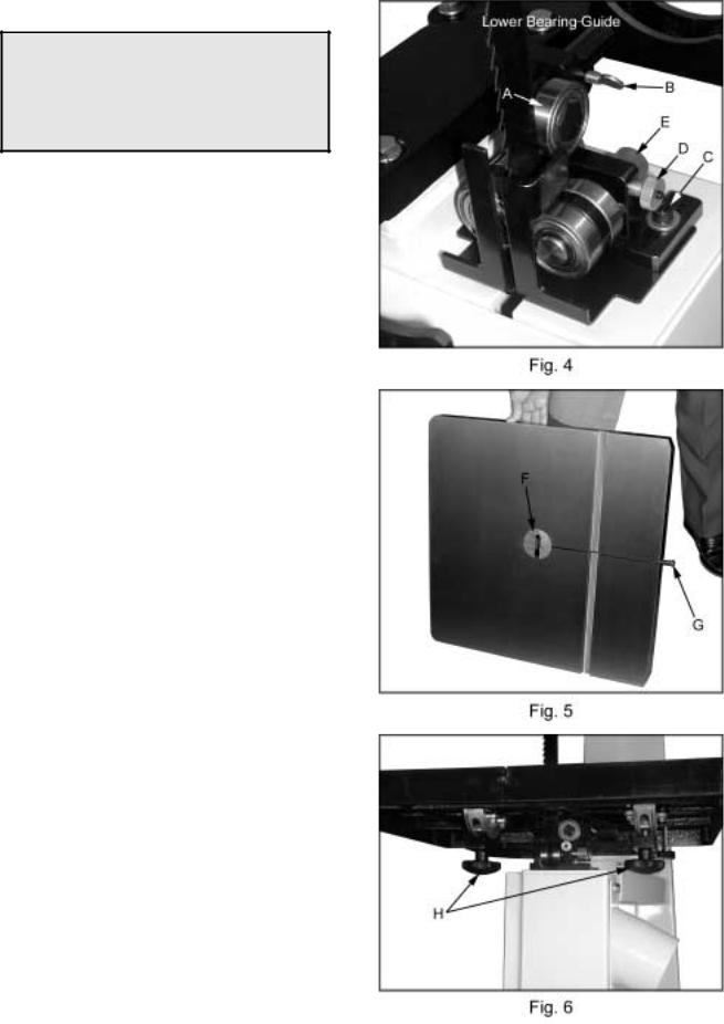
3.Adjust the back-up bearing (A, Fig. 4) so that it is 0.003” away from the back of the blade, about the thickness of a piece of paper. To make this adjustment loosen thumb screw (B, Fig. 4) and slide the bearing, and bearing post into position. Tighten thumb screw.
4.Loosen the socket head cap screw (C, Fig.
4)and slide the bearing assembly until the bearing guides rest just behind the gullet of the blade teeth. You may need to readjust the back-up bearing. Tighten socket head cap screw.
5.Loosen the thumb screw (D, Fig. 4) and turn adjusting screw (E, Fig. 4) clockwise or counter-clockwise until the bearing is 0.003” away from the side of the blade, about the thickness of a piece of paper.
6.Adjust the opposite side bearing.
7.Tighten thumb screw (D, Fig. 4). Check to make sure the adjustments have not changed and the bearing guides do not pinch the blade.
Mounting the Table
1.With help from another person mount the table. Remove the table insert (F, Fig. 5) and table pin (G, Fig. 5).
2.Slide saw blade through slot in table where the table pin was located. Rotate the table 90 degrees so that the miter slot is parallel to the blade, and to the right of the blade when facing the bandsaw.
3.Line up the trunnions so that the bolts feed through the trunnion support bracket. Secure the table with two lock knobs (H, Fig. 6). Reinstall the table insert and table pin.
7
Adjusting 90 Degree Table Stop
1.Blade tension must be properly adjusted prior to adjusting 90 degree stop, see “Adjusting Blade Tension” page 13.
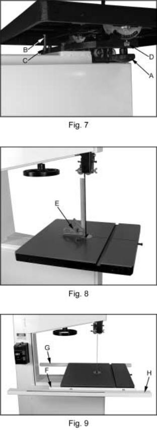
2.Loosen lock knobs (A, Fig. 7) and tilt table until it rests against table stop bolt (B, Fig. 7). Tighten knobs.
3.Use a square (E, Fig. 8) placed on the table and against the blade to see if the table is 90 degrees to the blade.
4.If an adjustment is necessary, loosen the lock knobs. Tilt the table until it is square to the blade, and tighten the lock knobs.
5.Loosen lock nut (C, Fig. 7) and turn table stop bolt (B, Fig. 7) until it contacts the table. Tighten the nut (C, Fig. 7) to hold table stop in place. When tightening the nut hold the table stop bolt in place with a wrench to prevent movement.
6.If necessary, adjust pointer (D, Fig. 7) to zero.
Rail Assembly
1.Attach the front rail (F, Fig. 9) to the cast iron table with two 1/4” x 5/8” hex cap bolts, two 1/4” lock washers, and two 1/4” flat washers. Bolts should be in approximately the center of the slot. Hand tighten only at this time.
2.Attach the rear rail (G, Fig. 9) to the table with two 1/4” x 5/8” hex cap bolts, two 1/4” lock washers, and two 1/4” flat washers. Bolts should be in approximately the center of the slot. Hand tighten only at this time.
3.Push the front, and rear rails up as far as they will go.
4.Tighten the four hex cap bolts holding the front, and rear rails to the table. Do not over tighten the bolts.
5.Attach the guide tube (H, Fig. 9) to the front rail with five 1/4” x 5/8” hex cap bolts, five 1/4” lock washers, and five 1/4” flat washers. Bolts should be in approximately the center of the slot.
8
 Loading...