


 Loading...
This Manual is Bookmarked
Operating Instructions and Parts Manual
18” Band Saw
Models: JWBS-18X, JWBS-18X-3
WMH TOOL GROUP |
|
2420 Vantage Drive |
|
Elgin, Illinois 60123 |
Part No. M-710750 |
Ph.: 800-274-6848 |
Revision B 5/05 |
www.wmhtoolgroup.com |
Copyright © WMH Tool Group |

This manual has been prepared for the owner and operators of JET JWBS-18X and JWBS-18X-3 Band Saws. Its purpose, aside from machine operation, is to promote safety using accepted operating and maintenance procedures. To obtain maximum life and efficiency from your band saw and to aid in using it safely, please read this manual thoroughly and follow the instructions carefully.
Warranty
WMH Tool Group warrants every product it sells. If one of our tools needs service or repair, one of our Authorized Repair Stations located throughout the United States can give you quick service.
In most cases, any one of these WMH Tool Group Repair Stations can authorize warranty repair, assist you in obtaining parts, or perform routine maintenance and major repair on your JET, Wilton, or Powermatic tools.
For the name of an Authorized Repair Station in your area, please call 1-800-274-6848, or visit www.wmhtoolgroup.com
More Information
WMH Tool Group is consistently adding new products to the line. For complete, up-to-date product information, check with your local WMH Tool Group distributor, or visit www.wmhtoolgroup.com
WMH Tool Group Warranty
WMH Tool Group (including JET, Wilton and Powermatic brands) makes every effort to assure that its products meet high quality and durability standards and warrants to the original retail consumer/purchaser of our products that each product be free from defects in materials and workmanship as follow: 1 YEAR LIMITED WARRANTY ON ALL PRODUCTS UNLESS SPECIFIED OTHERWISE. This Warranty does not apply to defects due directly or indirectly to misuse, abuse, negligence or accidents, normal wear-and- tear, repair or alterations outside our facilities, or to a lack of maintenance.
WMH TOOL GROUP LIMITS ALL IMPLIED WARRANTIES TO THE PERIOD SPECIFIED ABOVE, FROM THE DATE THE PRODUCT WAS PURCHASED AT RETAIL. EXCEPT AS STATED HEREIN, ANY IMPLIED WARRANTIES OR MERCHANTIBILITY AND FITNESS ARE EXCLUDED. SOME STATES DO NOT ALLOW LIMITATIONS ON HOW LONG THE IMPLIED WARRANTY LASTS, SO THE ABOVE LIMITATION MAY NOT APPLY TO YOU. WMH TOOL GROUP SHALL IN NO EVENT BE LIABLE FOR DEATH, INJURIES TO PERSONS OR PROPERTY, OR FOR INCIDENTAL, CONTINGENT, SPECIAL, OR CONSEQUENTIAL DAMAGES ARISING FROM THE USE OF OUR PRODUCTS. SOME STATES DO NOT ALLOW THE EXCLUSION OR LIMITATION OF INCIDENTAL OR CONSEQUENTIAL DAMAGES, SO THE ABOVE LIMITATION OR EXCLUSION MAY NOT APPLY TO YOU.
To take advantage of this warranty, the product or part must be returned for examination, postage prepaid, to an Authorized Repair Station designated by our office. Proof of purchase date and an explanation of the complaint must accompany the merchandise. If our inspection discloses a defect, we will either repair or replace the product, or refund the purchase price if we cannot readily and quickly provide a repair or replacement, if you are willing to accept a refund. We will return repaired product or replacement at WMH Tool Group’s expense, but if it is determined there is no defect, or that the defect resulted from causes not within the scope of WMH Tool Group’s warranty, then the user must bear the cost of storing and returning the product. This warranty gives you specific legal rights; you may also have other rights, which vary from state to state.
WMH Tool Group sells through distributors only. WMH Tool Group reserves the right to effect at any time, without prior notice, those alterations to parts, fittings, and accessory equipment, which they may deem necessary for any reason whatsoever.
2
Table of Contents |
|
Warranty........................................................................................................................................................ |
2 |
Table of Contents.......................................................................................................................................... |
3 |
Warning......................................................................................................................................................... |
4 |
Introduction ................................................................................................................................................... |
6 |
Specifications ................................................................................................................................................ |
6 |
Grounding Instructions .................................................................................................................................. |
7 |
1.75 HP Single Phase Motor ..................................................................................................................... |
7 |
115 Volt Operation..................................................................................................................................... |
7 |
230 Volt Operation..................................................................................................................................... |
7 |
3 HP Single Phase Motor .......................................................................................................................... |
8 |
230 Volt Operation..................................................................................................................................... |
8 |
Extension cords ......................................................................................................................................... |
8 |
Unpacking ..................................................................................................................................................... |
9 |
Contents of Shipping Container ................................................................................................................ |
9 |
Assembly..................................................................................................................................................... |
10 |
Handwheel............................................................................................................................................... |
10 |
Mounting the Table.................................................................................................................................. |
10 |
Rail Assembly.......................................................................................................................................... |
10 |
Fence Assembly and Adjustment............................................................................................................ |
11 |
Resaw Guide ........................................................................................................................................... |
13 |
Miter Gauge............................................................................................................................................. |
13 |
Adjustments ................................................................................................................................................ |
14 |
Adjusting 90 Degree Table Stop ............................................................................................................. |
14 |
Installing/Changing Blades...................................................................................................................... |
15 |
Blade Tension.......................................................................................................................................... |
16 |
Blade Tracking......................................................................................................................................... |
16 |
Overview – Bearing Adjustments ............................................................................................................ |
17 |
Upper Bearing Adjustments .................................................................................................................... |
17 |
Lower Bearing Adjustments .................................................................................................................... |
18 |
Blade Lead .............................................................................................................................................. |
19 |
Replacing the V-Belt................................................................................................................................ |
20 |
Belt Tension............................................................................................................................................. |
20 |
Pulley Alignment...................................................................................................................................... |
21 |
Electrical Connections................................................................................................................................. |
21 |
Operation..................................................................................................................................................... |
22 |
General Procedure .................................................................................................................................. |
22 |
Ripping .................................................................................................................................................... |
22 |
Crosscutting............................................................................................................................................. |
22 |
Resawing................................................................................................................................................. |
23 |
Saw Blade Selection................................................................................................................................ |
23 |
Blade Breakage ....................................................................................................................................... |
24 |
Maintenance................................................................................................................................................ |
24 |
Blade Selection Guide................................................................................................................................. |
25 |
Optional Accessories: Band Saw Blades.................................................................................................... |
27 |
Replacement Parts...................................................................................................................................... |
27 |
Parts List: Upper Wheel Assembly.......................................................................................................... |
28 |
Upper Wheel Assembly........................................................................................................................... |
29 |
Parts List: Lower Wheel and Motor Assembly ........................................................................................ |
30 |
Lower Wheel and Motor Assembly.......................................................................................................... |
31 |
Parts List: Blade Guide Assembly ........................................................................................................... |
32 |
Blade Guide Assembly ............................................................................................................................ |
34 |
Parts List: Table and Fence Assembly.................................................................................................... |
35 |
Table and Fence Assembly..................................................................................................................... |
37 |
Electrical Connections................................................................................................................................. |
38 |
3

1.Read and understand the entire owner's manual before attempting assembly or operation.
2.Read and understand the warnings posted on the machine and in this manual. Failure to comply with all of these warnings may cause serious injury.
3.Replace the warning labels if they become obscured or removed.
4.This band saw is designed and intended for use by properly trained and experienced personnel only. If you are not familiar with the proper and safe operation of a band saw, do not use until proper training and knowledge have been obtained.
5.Do not use this band saw for other than its intended use. If used for other purposes, WMH Tool Group disclaims any real or implied warranty and holds itself harmless from any injury that may result from that use.
6.Always wear approved safety glasses/face shields while using this band saw. Everyday eyeglasses only have impact resistant lenses; they are not safety glasses.
7.Before operating this band saw, remove tie, rings, watches and other jewelry, and roll sleeves up past the elbows. Remove all loose clothing and confine long hair. Non-slip footwear or anti-skid floor strips are recommended. Do not wear gloves.
8.Wear ear protectors (plugs or muffs) during extended periods of operation.
9.Some dust created by power sanding, sawing, grinding, drilling and other construction activities contain chemicals known to cause cancer, birth defects or other reproductive harm. Some examples of these chemicals are:
•Lead from lead based paint.
•Crystalline silica from bricks, cement and other masonry products.
•Arsenic and chromium from chemically treated lumber.
Your risk of exposure varies, depending on how often you do this type of work. To reduce your exposure to these chemicals, work in a well-ventilated area and work with approved safety equipment, such as face or dust masks that are specifically designed to filter out microscopic particles.
10.Do not operate this machine while tired or under the influence of drugs, alcohol or any medication.
11.Make certain the switch is in the OFF position before connecting the machine to the power supply.
12.Make certain the machine is properly grounded.
13.Make all machine adjustments or maintenance with the machine unplugged from the power source.
14.Remove adjusting keys and wrenches. Form a habit of checking to see that keys and adjusting wrenches are removed from the machine before turning it on.
15.Keep safety guards in place at all times when the machine is in use. If removed for maintenance purposes, use extreme caution and replace the guards immediately.
16.Check damaged parts. Before further use of the machine, a guard or other part that is damaged should be carefully checked to determine that it will operate properly and perform its intended function. Check for alignment of moving parts, binding of moving parts, breakage of parts, mounting and any other conditions that may affect its operation. A guard or other part that is damaged should be properly repaired or replaced.
17.Provide for adequate space surrounding work area and non-glare, overhead lighting.
18.Keep the floor around the machine clean and free of scrap material, oil and grease.
19.Keep visitors a safe distance from the work area. Keep children away.
4

20.Make your workshop child proof with padlocks, master switches or by removing starter keys.
21.Give your work undivided attention. Looking around, carrying on a conversation and “horse-play” are careless acts that can result in serious injury.
22.Maintain a balanced stance at all times so that you do not fall or lean against the blade or other moving parts. Do not overreach or use excessive force to perform any machine operation.
23.Use the right tool at the correct speed and feed rate. Do not force a tool or attachment to do a job for which it was not designed. The right tool will do the job better and safer.
24.Use recommended accessories; improper accessories may be hazardous.
25.Maintain tools with care. Keep blades sharp and clean for the best and safest performance. Follow instructions for lubricating and changing accessories.
26.Turn off the machine before cleaning. Use a brush or compressed air to remove chips or debris — do not use your hands.
27.Do not stand on the machine. Serious injury could occur if the machine tips over.
28.Never leave the machine running unattended. Turn the power off and do not leave the machine until it comes to a complete stop.
29.Remove loose items and unnecessary work pieces from the area before starting the machine.
Familiarize yourself with the following safety notices used in this manual:
 This means that if precautions are not heeded, it may result in minor injury and/or possible machine damage.
 This means that if precautions are not heeded, it may result in serious injury or possibly even death.
- - SAVE THESE INSTRUCTIONS - -
5
Introduction
This manual is provided by Jet covering the safe operation and maintenance procedures for models JWBS-18X and JWBS-18X-3 Band Saws. This manual contains instructions on installation, safety precautions, general operating procedures, maintenance instructions and parts breakdown. This machine has been designed and constructed to provide years of trouble free operation if used in accordance with instructions set forth in this manual. If there are any questions or comments, please contact either your local supplier or WMH Tool Group. WMH Tool Group can also be reached at our web site: www.wmhtoolgroup.com.
Specifications
Model Number.............................................................. |
|
JWBS-18X |
........................................... JWBS - 18X-3 |
Stock Number .................................................................... |
|
710750 |
.................................................... 710751 |
Cutting Capacity (height) (in.) .................................................... |
12 |
............................................................ 12 |
|
Cutting Capacity (width) (in.)................................................ |
18-3/8 ...................................................... |
18 -3/8 |
|
Maximum Rip Left of Blade w/Fence (in.) ............................ |
16-1/2 ...................................................... |
16 - 1/2 |
|
Maximum Rip Right of Blade w/Fence (in.)............................ |
7-5/8 ........................................................ |
7 -5/8 |
|
Blade Length (in.)..................................................................... |
|
137 .......................................................... |
137 |
Blade Speed (SFPM) ............................................................. |
|
3000 ........................................................ |
3000 |
Minimum Blade Width (in.)........................................................ |
1/8 ........................................................... |
1/8 |
|
Maximum Blade Width (in.).................................................... |
1-1/2 ........................................................ |
1 -1/2 |
|
Table Size (in.) ................................................................. |
|
19” x 19” .................................................. |
19” x 19” |
Table Tilt (degrees) ................................................... |
|
45°R to 10°L ............................................ |
45 ° R to 10°L |
Table Height from Floor (in.) ................................................ |
37-1/2 ...................................................... |
37 -1/2 |
|
Wheel Diameter (in.) ............................................................ |
|
18-5/8 ...................................................... |
18 -5/8 |
Dust Chute Diameter (in.) ........................................................... |
4 .............................................................. |
4 |
|
Overall Dimensions (HxWxD) (in.) ....................... |
73 x 39 x 32-1/2 ............................................ |
73 x 39 x 35 |
|
Motor ............................ |
1.75 HP, 1Ph, 115/230V (prewired 115V) ..................................... |
3 HP, 1Ph, 230V |
|
Net Weight (approx.) (lbs.)....................................................... |
418 .......................................................... |
425 |
|
Shipping Weight (approx.) (lbs.) .............................................. |
493 ......................................................... |
500 |
|
The above specifications were current at the time this manual was published, but because of our policy of continuous improvement, WMH Tool Group reserves the right to change specifications at any time and without prior notice, without incurring obligations.
6

Grounding Instructions
1.75 HP Single Phase Motor
 This machine must be grounded while in use to protect the operator from electric shock.
In the event of a malfunction or breakdown, grounding provides a path of least resistance for electric current to reduce the risk of electric shock. This tool is equipped with an electric cord having an equipment-grounding conductor and a grounding plug. The plug must be plugged into a matching outlet that is properly installed and grounded in accordance with all local codes and ordinances.
Do not modify the plug provided. If it will not fit the outlet, have the proper outlet installed by a qualified electrician.
Improper connection of the equipmentgrounding conductor can result in a risk of electric shock. The conductor, with insulation having an outer surface that is green with or without yellow stripes, is the equipmentgrounding conductor. If repair or replacement of the electric cord or plug is necessary, do not connect the equipment-grounding conductor to a live terminal.
Check with a qualified electrician or service personnel if the grounding instructions are not completely understood, or if in doubt as to whether the tool is properly grounded. Use only three wire extension cords that have three-prong grounding plugs and three-pole receptacles that accept the tool’s plug.
Repair or replace a damaged or worn cord immediately.
115 Volt Operation
If your band saw's Stock No. is 710750, it is wired from the factory for 115 volt operation. The power cord has a plug that looks like A, Fig. 1. and is used in an outlet that looks like B, Fig. 1. A temporary adapter with a grounding ear secured with a screw (C, Fig. 1) may be used to connect this plug to a two-pole receptacle if a properly grounded outlet is not available. The temporary adapter should only be used until a properly grounded outlet can be installed by a qualified electrician. This adapter is not applicable in Canada. The green colored grounding ear, lug, or tab, extending from the adapter, must be connected to a permanent
ground such as a properly grounded outlet box, as shown in C, Fig. 1.
Figure 1
230 Volt Operation
If 230V, single phase operation is desired, the following instructions must be followed:
1.Disconnect the machine from the power source.
2.This band saw is supplied with four motor leads that are connected for 115V operation as shown in A, Fig. 2. For 230V operation reconnect the leads as shown in B, Fig. 2.
3.The 115V attachment plug supplied with the band saw (C, Fig. 2) must be replaced with a UL/CSA listed plug suitable for 230V operation (D, Fig. 2). Contact your local Authorized JET Service Center or qualified electrician for proper procedures to install the plug. The band saw must comply with all local and national codes after the 230V plug is installed.
4.The band saw with a 230V plug should only be connected to an outlet having the same configuration (D, Fig. 2). No adapter is available or should be used with the 230V plug.
Important: In all cases (115 or 230 volts), make certain the receptacle in question is properly grounded. If you are not sure, have a registered electrician check the receptacle.
Figure 2
7
Grounding Instructions
3 HP Single Phase Motor
 Electrical connections must be made by a qualified electrician in compliance with all relevant codes. This machine must be properly grounded to help prevent electrical shock and possible fatal injury.
This machine must be grounded. In the event of a malfunction or breakdown, grounding provides a path of least resistance for electric current to reduce the risk of electric shock.
Improper connection of the equipmentgrounding conductor can result in a risk of electric shock. The conductor with insulation having an outer surface that is green with or without yellow stripes, is the equipmentgrounding conductor. If repair or replacement of the electric cord or plug is necessary, do not connect the equipment-grounding conductor to a live terminal.
Check with a qualified electrician or service personnel if the grounding instructions are not completely understood, or if in doubt as to whether the tool is properly grounded.
Repair or replace a damaged or worn cord immediately.
Make sure the voltage of your power supply matches the specifications on the motor plate of the band saw. The machine should be connected to a dedicated circuit.
230 Volt Operation
If your band saw's Stock No. is 710751, it is wired from the factory for 230 volt operation You may either install a plug or “hard-wire” the band saw directly to a control panel.
If connecting a plug, use a proper UL/CSA listed 2-pole, 3-wire grounding plug suitable for 230V operation.
If the band saw is to be hard-wired to a panel, make sure a disconnect is available for the
operator. During hard-wiring of the band saw, make sure the fuses have been removed or the breakers have been tripped in the circuit to which the band saw will be connected. Place a warning placard on the fuse holder or circuit breaker to prevent it being turned on while the machine is being wired.
Extension cords
The use of an extension cord is not recommended for this band saw. But if one is necessary, make sure the cord rating is suitable for the amperage listed on the machine’s motor plate. An undersize cord will cause a drop in line voltage resulting in loss of power and overheating.
Use the chart in Table 1 as a general guide in choosing the correct size cord. If in doubt, use the next heavier gauge. The smaller the gauge number, the heavier the cord.
Recommended Gauges (AWG) of Extension Cords
|
|
Extension Cord Length * |
|
|||
|
|
|
|
|
|
|
Amps |
25 |
50 |
75 |
100 |
150 |
200 |
feet |
feet |
feet |
feet |
feet |
feet |
|
|
|
|
|
|
|
|
< 5 |
16 |
16 |
16 |
14 |
12 |
12 |
|
|
|
|
|
|
|
5 to 8 |
16 |
16 |
14 |
12 |
10 |
NR |
|
|
|
|
|
|
|
8 to 12 |
14 |
14 |
12 |
10 |
NR |
NR |
|
|
|
|
|
|
|
12 to 15 |
12 |
12 |
10 |
10 |
NR |
NR |
|
|
|
|
|
|
|
15 to 20 |
10 |
10 |
10 |
NR |
NR |
NR |
|
|
|
|
|
|
|
21 to 30 |
10 |
NR |
NR |
NR |
NR |
NR |
|
|
|
|
|
|
|
*based on limiting the line voltage drop to 5V at 150% of the rated amperes.
NR: Not Recommended.
Table 1
8

Unpacking
Contents of Shipping Container
1 |
Band Saw |
1 |
Table |
1 |
Fence and Rail Assembly |
1 |
Resaw Guide and Knob |
1 |
Miter Gauge |
1 |
Owner’s Manual |
1 |
Warranty Card |
1Accessory Package Contains:
Hardware Bag
2 Knobs
1 Handle
1 10/12mm Wrench
Fence Hardware Bag
4 Hex Cap Screws
4 Flat Washers
4 Lock Washers
Rail Hardware Bag
9 Hex Cap Screws
9 Flat Washers
9 Lock Washers
1.Remove the crate and packing material from the band saw except for the transport skid on the bottom.
2.Move the saw to its permanent working location. The site should be dry, well lit, and have enough room to handle long stock and the service and/or adjustment of the machine from any side.
3.Move the band saw off the skid.
4.Clean all rust protected surfaces with a mild solvent or diesel fuel and a soft cloth. Do not use lacquer thinner, paint thinner, or gasoline. These will damage painted surfaces.
Tools Included for Assembly
1. 10/12mm Open End Wrench
Tools Required for Assembly & Adjustments
2. 14mm Open End Wrench
1. Cross Point Screw Driver
1. Combination Square
9
Assembly
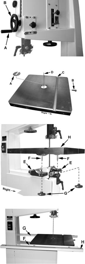
Handwheel
Attach the handle (A, Fig. 3) to the handwheel (B, Fig. 3).
Mounting the Table
Important: The table is heavy. Mounting with the help of another person is recommended.
Referring to Figures 4 and 5:
1. Remove the table insert (A) and tapered pin (B).
2.Slide the table so the saw blade (D) passes through the slot where the tapered pin (B) was located.
3.Rotate the table 90 degrees so that the miter slot (C) is parallel to the blade (D) and to the right of the blade when facing the band saw as viewed in Figure 5.
4.Line up the table (H) to the trunnions so that the bolts (F) feed through the support bracket
(E). Secure the table with two lock knobs (G).
Reinstall the table insert (A) and tapered pin (B).
Rail Assembly
Referring to Figure 6:
1.Attach the front rail (F) to the cast iron table with two 1/4” x 5/8” hex cap screws, two 1/4” lock washers, and two 1/4” flat washers. The screws should be in approximately the center of the slot. Hand-tighten only at this time.
2.Attach the rear rail (G) to the table with two 1/4” x 5/8” hex cap screws, two 1/4” lock washers, and two 1/4” flat washers. Screws should be in approximately the center of the slot. Handtighten only at this time.
3.Push the front and rear rails up as far as they will go.
4.Using a 10mm wrench, tighten the four hex cap screws holding the front and rear rails to the table. Do not over-tighten the screws.
5.Attach the guide tube (H) to the front rail with five 1/4” x 5/8” hex cap screws, five 1/4” lock washers, and five 1/4” flat washers. Screws should be in approximately the center of the slot.
Hand-tighten the guide tube only at this time. You will be instructed to secure it later in the
Fence Assembly and Adjustment section.
10
Figure 3
Figure 4
Figure 5
Figure 6
Fence Assembly and Adjustment
Assembling the Fence to Fence Body
Referring to Figure 7:
1.Attach the fence (A) to the fence body (B) with four 5/16” x 3/4” hex cap screws (C), four 5/16” lock washers (D), and four 5/16” flat washers
(E). Hand-tighten only at this time.
Figure 7
Assembling the Rear Hook
Referring to Figure 8:
2.Thread a 1/4"-20 hex nut (B) onto the pad’s threaded stud (A) and insert through the fence (C) so the threaded stud is now inside the fence.
3.Place the rear hook (D) on the threaded stud.
Finish the assembly by placing a 1/4" flat washer (E), 1/4" lock washer (F) and 1/4" hex nut (G) on the threaded stud and finger tighten.
Note: Adjust for a gap of approximately 1/8" between the pad (A) and hook (D) and as shown in the inset.
4.Tighten the assembly using two 10mm wrenches.
Figure 8
11

Fence Adjustment
5. Place the fence assembly onto the guide rail (D, Fig. 9) and against the edge of the miter slot (C, Fig. 9). The hook at the rear of the fence should fit under the rear rail (see Figure 12).
The fence must align parallel to the miter slot along the entire length of the fence.
If adjustment is necessary:
6.Lock the fence by pushing down the lock handle (A, Fig. 9). Because the screws are only hand-tight, you can shift the fence slightly as needed until the fence is parallel the miter slot.
7.When the fence has been properly aligned to the miter slot, tighten the four hex cap screws (B, Fig. 9) with a 12mm wrench. Make sure the fence remains parallel to the miter slot as you tighten the screws.
Note: This alignment will again be checked once the guide rail has been tightened.
Figure 9
8.Move the fence assembly to the other side of the blade as shown in Figure 10 so that the pointer (B, Fig. 10) on the fence body points to zero on the scale. Lock the fence by pushing the handle (A, Fig. 10) down.
9.Move the guide rail (D, Fig. 10) with the locked fence until the fence is flush against the blade (C, Fig. 10). Do not unlock the fence to perform this. Move the fence and guide rail together when establishing the zero point.
Important: Do not force the fence into the blade so that the blade bends.
10.With a 10mm wrench, tighten the five hex cap screws located on the bottom of the front rail that hold the guide rail to the front rail.
Note: After tightening the guide rail, double check that the fence is still parallel to the miter slot. Make additional adjustments if needed.
Figure 10
12
Loading...