


OWNER’S MANUAL
JJ-8CS Woodworking Jointer
JET EQUIPMENT & TOOLS, INC. |
P.O. BOX 1349 |
Phone:253-351-6000 |
A WMH Company |
Auburn, WA 98071-1349 |
Fax: 1-800-274-6840 |
www.jettools.com |
e-mail jet@jettools.com |
M-708458 06/01 |

This manual has been prepared for the owner and operators of a JET JJ-8CS. Its purpose, aside from machine operation, is to promote safety through the use of accepted correct operating and maintenance procedures. Completely read the safety and maintenance instructions before operating or servicing the machine. To obtain maximum life and efficiency from your jointer, and to aid in using the machine safely, read this manual thoroughly and follow all instructions carefully.
Warranty & Service
The JET Group warrants every product it sells. If one of our tools needs service or repair, one of our Authorized Repair Stations located throughout the United States can give you quick service.
In most cases, any one of these JET Group Repair Stations can authorize warranty repair, assist you in obtaining parts, or perform routine maintenance and major repair on your JET, Performax or Powermatic tools.
For the name of an Authorized Repair Station in your area, please call 1-800-274-6848.
More Information
Remember, the JET Group is consistently adding new products to the line. For complete, up-to-date product information, check with your local JET Group distributor.
JET Group Warranty
The JET Group (including Performax and Powermatic brands) makes every effort to assure that its products meet high quality and durability standards and warrants to the original retail consumer/purchaser of our products that each product be free from defects in materials and workmanship as follow: 1 YEAR LIMITED WARRANTY ON ALL PRODUCTS UNLESS SPECIFIED OTHERWISE. This Warranty does not apply to defects due directly or indirectly to misuse, abuse, negligence or accidents, normal wear-and-tear, repair or alterations outside our facilities, or to a lack of maintenance.
THE JET GROUP LIMITS ALL IMPLIED WARRANTIES TO THE PERIOD SPECIFIED ABOVE, FROM THE DATE THE PRODUCT WAS PURCHASED AT RETAIL. EXCEPT AS STATED HEREIN, ANY IMPLIED WARRANTIES OR MERCHANTIBILITY AND FITNESS ARE EXCLUDED. SOME STATES DO NOT
ALLOW LIMITATIONS ON HOW LONG THE IMPLIED WARRANTY LASTS, SO THE ABOVE LIMITATION MAY NOT APPLY TO YOU. THE JET GROUP SHALL IN NO EVENT BE LIABLE FOR DEATH, INJURIES TO PERSONS OR PROPERTY, OR FOR INCIDENTAL, CONTINGENT, SPECIAL, OR CONSEQUENTIAL DAMAGES ARISING FROM THE USE OF OUR PRODUCTS. SOME STATES DO NOT ALLOW THE EXCLUSION OR LIMITATION OF INCIDENTAL OR CONSEQUENTIAL DAMAGES, SO THE ABOVE LIMITATION OR EXCLUSION MAY NOT APPLY TO YOU.
To take advantage of this warranty, the product or part must be returned for examination, postage prepaid, to an Authorized Repair Station designated by our office. Proof of purchase date and an explanation of the complaint must accompany the merchandise. If our inspection discloses a defect, we will either repair or replace the product, or refund the purchase price if we cannot readily and quickly provide a repair or replacement, if you are willing to accept a refund. We will return repaired product or replacement at JET’s expense, but if it is determined there is no defect, or that the defect resulted from causes not within the scope of JET’s warranty, then the user must bear the cost of storing and returning the product. This warranty gives you specific legal rights; you may also have other rights which vary from state to state.
The JET Group sells through distributors only. Members of the JET Group reserve the right to effect at any time, without prior notice, those alterations to parts, fittings, and accessory equipment which they may deem necessary for any reason whatsoever.
2
WARNING
Wear eye protection.
Always keep cutterhead and drive guards in place and in proper operating condition. Do not remove guard for rabbeting operations.
Never make a jointing, planing, or rabbeting cut deeper than 1/8”.
Always use hold-down/push blocks for jointing material narrower than 3”, or planing material
thinner than 3”.
Never perform jointing, planing, or rabbeting cuts (with jointers provided with a rabbeting guard) on pieces shorter than 8” (203mm) in length.
•Keep guards in place and in working order.
•Remove adjusting keys and wrenches. Form a habit of checking to see that keys and adjusting wrenches are removed from the machine before turning it on.
•Keep the work area clean. Cluttered areas and benches invite accidents.
•Don’t use in a dangerous environment. Don’t use power tools in damp or wet locations, or expose them to rain. Keep work area well lighted.
•Keep children away. All visitors should be kept a safe distance from the work area.
•Make the workshop kidproof with padlocks, master switches, or by removing starter keys.
•Don’t force the machine. It will do the job better and safer at the rate for which it was designed.
•Use the right tool. Don’t force a machine or attachment to do a job for which it was not designed.
•Use the proper extension cord. Make sure your extension cord is in good condition. When using an extension cord, be sure to use one heavy enough to carry the current your machine will draw. An undersized cord will cause a drop in the line voltage resulting in power loss and overheating. The following table shows the correct size to use depending on the cord length and nameplate ampere rating. If in doubt, use the next heavier gauge. Remember, the smaller the gauge number, the heavier the cord.
Volts |
|
Total Length of Cord in Feet |
|
|
||
|
|
|
|
|
|
|
120V |
25 |
50 |
|
100 |
|
150 |
|
|
|
|
|
|
|
240V |
50 |
100 |
|
200 |
|
300 |
|
|
|
|
|
|
|
|
|
|
AWG |
|
|
|
|
|
|
|
|
|
|
|
14 |
12 |
|
|
Not Recommended |
|
|
|
|
|
|
|
|
•Wear proper apparel. Do not wear loose clothing, gloves, neckties, rings, bracelets, or other jewelry which may get caught in moving parts. Nonslip footwear is recommended. Wear protective hair covering to contain long hair.
•Always use safety glasses. Also use a face or dust mask if the cutting operation is dusty. Everyday eyeglasses only have impact resistant lenses; they are not safety glasses.
•Secure work. Use clamps or a vise to hold the work when practical. It’s safer than using your hands and it frees both hands to operate the tool.
3
•Don’t overreach. Keep proper footing and balance at all times.
•Maintain tools with care. Keep tools sharp and clean for best and safest performance. Follow instructions for lubricating and changing accessories.
•Always disconnect the machine from the power source before servicing.
•Reduce the risk of unintentional starting. Make sure the switch is in the off position before plugging in.
•Use recommended accessories. Consult the operator’s manual for recommended accessories. The use of improper accessories may cause risk of injury to persons.
•Never stand on a machine. Serious injury could occur if the machine is tipped or if the blade is unintentionally contacted.
•Check damaged parts. Before further use of the machine, a guard or other part that is damaged should be carefully checked to determine that it will operate properly and perform its intended function - check for alignment of moving parts, binding of moving parts, breakage of parts, mounting, and any other conditions that may affect its operation. A guard or other part that is damaged should be properly repaired or replaced.
•Direction of feed. Feed work into the blade against the direction of rotation of the blade only.
•Never leave the machine running unattended. Turn power off. Don’t leave the machine until it comes to a complete stop.
•Some dust created by power sanding, sawing, grinding, drilling and other construction activities contains chemicals known to cause cancer, birth defects or other reproductive harm. Some examples of these chemicals are:
*Lead from lead-based paint.
*Crystalline silica from bricks and cement and other masonry products.
*Arsenic and chromium from chemically-treated lumber.
Your risk from these exposures varies, depending on how often you do this type of work. To reduce your exposure to these chemicals, work in a well-ventilated area, and work with approved safety equipment, such as those dust masks that are specifically designed to filter out microscopic particles.
4
Table of Contents |
|
Warranty ......................................................................................................................................................... |
2 |
Warnings .................................................................................................................................................... |
3-4 |
Table of Contents ........................................................................................................................................... |
5 |
Introduction ..................................................................................................................................................... |
5 |
Levers and Controls ....................................................................................................................................... |
6 |
Specifications ................................................................................................................................................. |
6 |
Contents of Shipping Cartons ......................................................................................................................... |
7 |
Tools Required for Assembly .......................................................................................................................... |
7 |
Unpacking and Cleanup ................................................................................................................................. |
7 |
Installing Bed to Stand .................................................................................................................................... |
8 |
Installing Handwheels ..................................................................................................................................... |
8 |
Assembling Knife-Setting Gauge .................................................................................................................... |
9 |
90o Fence Adjustment ..................................................................................................................................... |
9 |
45o Fence Adjustment ................................................................................................................................... |
10 |
Leveling Outfeed Table with Cutterhead Knives .............................................................................................. |
10 |
Installing V-Belts ........................................................................................................................................... |
12 |
Installing Cutterhead Guard ........................................................................................................................... |
12 |
Installing Access Cover ................................................................................................................................. |
13 |
Installing Dust Chute ..................................................................................................................................... |
13 |
Electrical Connections .................................................................................................................................. |
13 |
Operation ...................................................................................................................................................... |
14 |
Jointing Warped Material ............................................................................................................................... |
15 |
Direction of Grain .......................................................................................................................................... |
15 |
Bevel Cut ...................................................................................................................................................... |
15 |
Taper Cut ...................................................................................................................................................... |
16 |
Rabbet Cut .................................................................................................................................................... |
16 |
Removing and Replacing Knives .................................................................................................................... |
16 |
Gib Adjustment ............................................................................................................................................. |
17 |
Lubrication .................................................................................................................................................... |
17 |
Blade Care .................................................................................................................................................... |
17 |
Sharpening the Knives ................................................................................................................................... |
18 |
Cutterhead Removal ...................................................................................................................................... |
18 |
Troubleshooting ............................................................................................................................................. |
19 |
Fence Assembly Breakdown & Parts List ................................................................................................ |
20-21 |
Bed Assembly Breakdown & Parts List .................................................................................................... |
22-23 |
Stand and Motor Assembly Breakdown & Parts List ................................................................................. |
24-25 |
Cutterhead Assembly ............................................................................................................................... |
26-27 |
Wiring Diagram ............................................................................................................................................. |
28 |
Introduction
The JET JJ-8CS woodworking jointer you have purchased is a high quality machine tool that will give you years of superior service. You will get maximum performance and enjoyment from your new jointer if you will take a few moments now to review the entire manual before beginning assembly and operation. Become familiar with the details of operation and be sure to review the controls page to start to become familiar with some of the unique words associated with a jointer.
The JET JJ-8CS jointer, as well as all JET products, are backed by a nationwide network of authorized distributors and/or service centers. Please contact your nearest distributor should you require parts or service. Parts are also available directly from JET by calling 1-800-274-6848.
Now that you have purchased a jointer, it is a good time to consider a dust collection system. See your local JET distributor for the complete line of dust collectors and the full line of JET Dust Collector Hoses and Accessories. Customize your installation and obtain maximum performance with JET’s dust hoods, hoses, clamps, fittings, and blast gates.
5
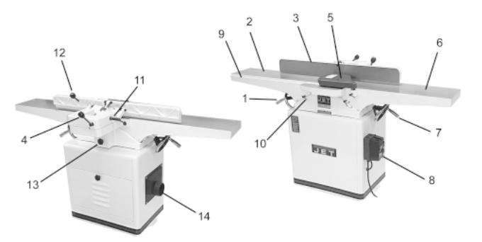
Levers and Controls
1. |
Handwheel for Outfeed Table |
8. |
On/Off Switch |
2. |
Outfeed Table |
9. |
Rabbeting Ledge |
3. |
Fence |
10. |
Table Lock Knob |
4. |
Fence Adjustment Handle |
11. |
Fence Tilt Lock Handle |
5. |
Cutter Guard |
12. |
Fence Control Handle |
6. |
Infeed Table |
13. |
Belt Guard |
7. |
Handwheel for Infeed Table |
14. |
Dust Chute |
Specifications: |
JJ-8CS |
Stock Number ..................................................................................................................... |
708458K |
Cutting Capacity .......................................................................................................... |
8” W x 1/2” D |
Cutterhead Speed ............................................................................................................ |
5,500 RPM |
Number of Knives ............................................................................................................................ |
3 |
Rabbeting Capacity ..................................................................................................................... |
1/2” |
Table Surface .......................................................................................................... |
9” W x 66-1/2” L |
Fence ..................................................................................................................... |
4” W x 38-1/2” L |
Blade Size ............................................................................................................. |
8” x 11/16” x 1/8” |
Fence Tilts Right and Left ............................................................................................................ |
45o |
Positive Stops ....................................................................................................................... |
45o, 90o |
Motor ............................................................................................................ |
2 HP, 1 Ph, 230V Only |
Net Weight (approx.) ............................................................................................................ |
398 lbs. |
Shipping Weight (approx.) .................................................................................................... |
470 lbs. |
The specifications in this manual are given as general information and are not binding. JET Equipment and Tools reserves the right to effect, at any time and without prior notice, changes or alterations to parts, fittings, and accessory equipment deemed necessary for any reason whatsoever.
6

Contents of Shipping Cartons
Note: unit shipped in two cartons.
Stand Carton
1. Stand with Motor
1. Stand Door
1. Dust Chute w/ Mounting Hardware
Main Unit Carton
1.Bed Assembly w/ Fence
1.Cutter Guard
3.Mounting Bolts
3.3/8" Lock Washers
1.Belt Guard
3.Hex Wrenches (3, 4 & 5mm)
2.Handwheels
2.Handles
2.V-Belts
1.Can of Touch-Up Paint
1.8/10mm Open End Wrench
1.12/14mm Open End Wrench
1.Owner’s Manual
1.Knife Gauge Assembly
1.Warranty Card
Tools Required for Assembly
#1 Cross Point Screw Driver
6-8" Adjustable Wrench or 17 and 19mm Wrench
Unpacking and Cleanup
1.Carefully remove all contents from both shipping cartons. Compare contents of the shipping cartons with the list of contents above. Place parts on a protected surface.
2.Report any shipping damage to your local distributor.
3.Clean all rust protected surfaces (bed, fence, etc.) with kerosene or diesel oil. Do not use gasoline, paint thinner, mineral spirits, etc. These may damage painted surfaces.
CAUTION
Cutterhead blades are extremely sharp! Use care when cleaning!
4.Apply a thin layer of paste wax to the bright surfaces of the fence and tables to prevent rust.
5.Set packing material and shipping cartons to the side. Do not discard until machine has been set up and is running properly.
7
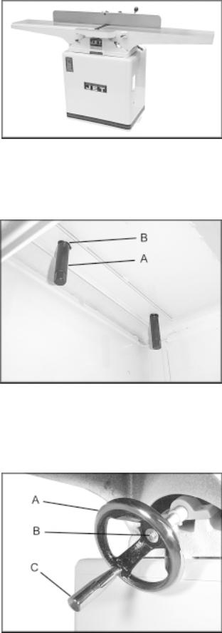
Installing Bed to Stand
1.Use an assistant or hoist mechanism to place bed assembly on top of stand. Be sure identification label on the bed faces the same direction as the label on the stand (Fig. 1).
2.Line up two holes in top of stand with holes in bed assembly by viewing through access door in stand.
3.Attach bed assembly to stand with two 3/8" lock bolts and lock washers (Fig. 2). Hand tighten only at this time.
4.Line up third hole in stand with hole in bed assembly by viewing through dust chute.
5.Install third 3/8" lock bolt and lock washer through dust chute to secure bed to stand.
6.Tighten all three mounting bolts with 14mm wrench.
Installing Handwheels
1.Remove protective tape from shaft, and remove screw and washer.
2.Press handwheel (A, Fig. 3) onto shaft, aligning the key way with the key. If necessary, use a hammer with a block of wood to tap the handwheel completely onto the shaft.
3.Re-install screw and washer (B, Fig. 3).
4.Mount handle (C, Fig. 3) onto handwheel.
Fig. 1
Fig. 2
Fig. 3
8

Assembling Knife-Setting Gauge
1.Place the two bases (A, Fig. 4) onto each end of the bar (B, Fig. 4). Snap the four E-rings (C, Fig. 4) into the grooves on the bar as shown.
Fig. 4
90° Fence Adjustment
Note: whenever making an adjustment to the fence, lift the fence up slightly after releasing the lock handle to avoid scratching the table.
1.Set infeed table to the same height as the outfeed table.
2.Move the fence by releasing lock handle (A, Fig. 5) and pushing the fence assembly until it overlaps the tables.
3. |
Adjust the fence to a 90° angle by releasing |
Fig. 5 |
|
lock handle (B, Fig. 5), pulling up on handle (C, |
|
|
Fig. 5), and re-tightening lock handle (B, Fig. |
|
|
5). |
|
4. |
Place a combination square on the infeed table. |
|
|
(Fig. 6) |
|
5. |
If fence is not square to table, release lock |
|
|
handle (B, Fig. 5), loosen nut (D, Fig. 5), and |
|
|
turn bolt (E, Fig. 5) until fence is square to table. |
|
6. |
Tighten nut (D, Fig. 5) to retain the setting. |
|
|
Tighten lock handle (B, Fig. 5). |
|
Fig. 6
9
 Loading...