


XA2125

®
Amplifier Installation and Operation
Installation Assistance
1.800.323.0221
365 / 24 / 7 @ www.jensen.com
Introduction
Thank you for purchasing a Jensen amplifier. The XA series
amplifiers offer extreme value and performance. Proper
installation is essential for optimal performance and long-term
reliability. Please read through this manual first to familiarize
yourself with your amplifier and its functions.
Warranty Service
If your Jensen amplifier should ever require service, you will
need to have the original dated receipt. If you ever need to
return the unit for any reason, always include the receipt with the
product.
XA2125
XA275
XA250
6236 XA2CH_E.p65 5/7/01, 2:07 PM1

2
XA2125, XA275, XA250
®
Contents
Features ......................................... 3
Installation..................................... 3
Before You Begin ......................................... 3
Disconnect Battery ........................................ 3
Supplies and Tools Needed ..........................3
Location and Mounting .................................. 4
Routing Wires................................................ 4
Wiring ............................................. 5
Power............................................................ 5
Power Terminal (+12V) ................................. 5
Ground Terminal (GND) ................................ 5
Remote Terminal (REM) ............................... 5
Fuses ............................................................ 5
Inputs, RCA Output,
Remote Level Control ................................. 6
Input Wiring ................................................... 6
Connecting Other Amps ................................ 6
Remote Level Control (XA2125) ................... 7
Speaker Wiring Options ............................. 7
Indicators and Controls.............................. 9
Crossover (X-OVER) .................................... 9
Power/Protect Light....................................... 9
Level.............................................................. 9
Bass .............................................................. 9
Testing ......................................... 10
Reconnect Battery ...................................... 10
Test Power Wiring ....................................... 10
Test Speaker Connections ..........................10
Troubleshooting........................... 11
Specifications .............................. 12
Warranty ...................................... 13
6236 XA2CH_E.p65 5/7/01, 2:07 PM2
®
XA2125, XA275, XA250
3
Installation
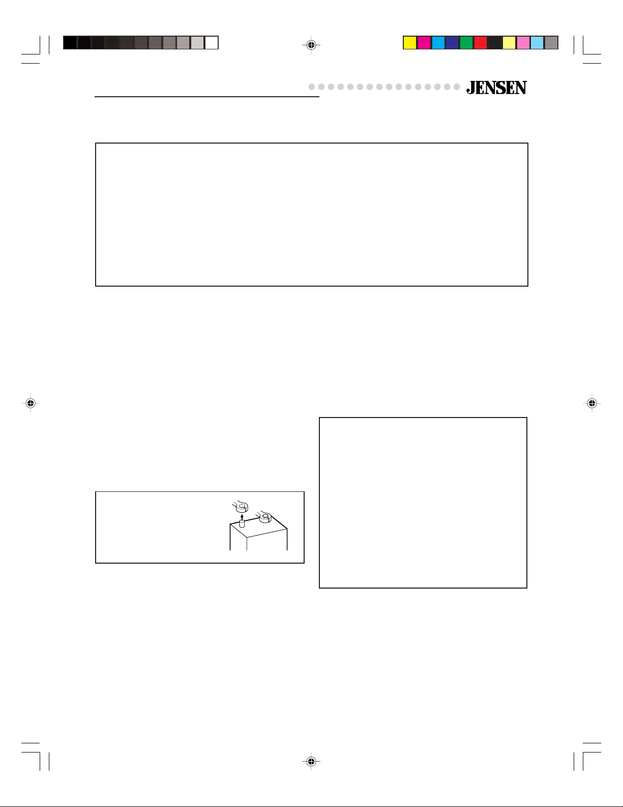
Disconnect Battery
Before you begin, always
disconnect the battery
negative terminal.
Before You Begin
Before you begin, you will need tools, supplies
and adapters. It is best to make sure you have
everything you need before you start.
+
–
Supplies and Tools Needed
Supplies
• Black electrical tape
• Amplifier Installation Kit
Tools
• Cordless drill with assortment of bits
• Flat and Phillips screwdrivers
• Wire cutters/strippers
• Crimping tool
• 12-volt test light or digital multimeter
• Wire brush, sandpaper or scraping tool
(ground connection to vehicle should be a
clean, unpainted metal surface)
Features
XA Series 2-channel amplifiers include:
• Easy access top mounted controls
• Continuously variable high pass/low pass
crossover
• 40Hz – 400Hz crossover frequency range
• Crossover mode selector switch
• Continuously variable bass boost, centered
at 45Hz
• Input level control
• Remote level control (XA2125)
• Traditional input circuitry – low and high level
inputs
• Pre-amp output for installation flexibility
• Dual status LED diagnostic indicator
• Thermal, short circuit and low impedance
protection circuitry
• PWM MOSFET power supply
• Discrete amplifier design with complementary
high current Bi-polar output stage
6236 XA2CH_E.p65 5/7/01, 2:07 PM3
4
XA2125, XA275, XA250
®
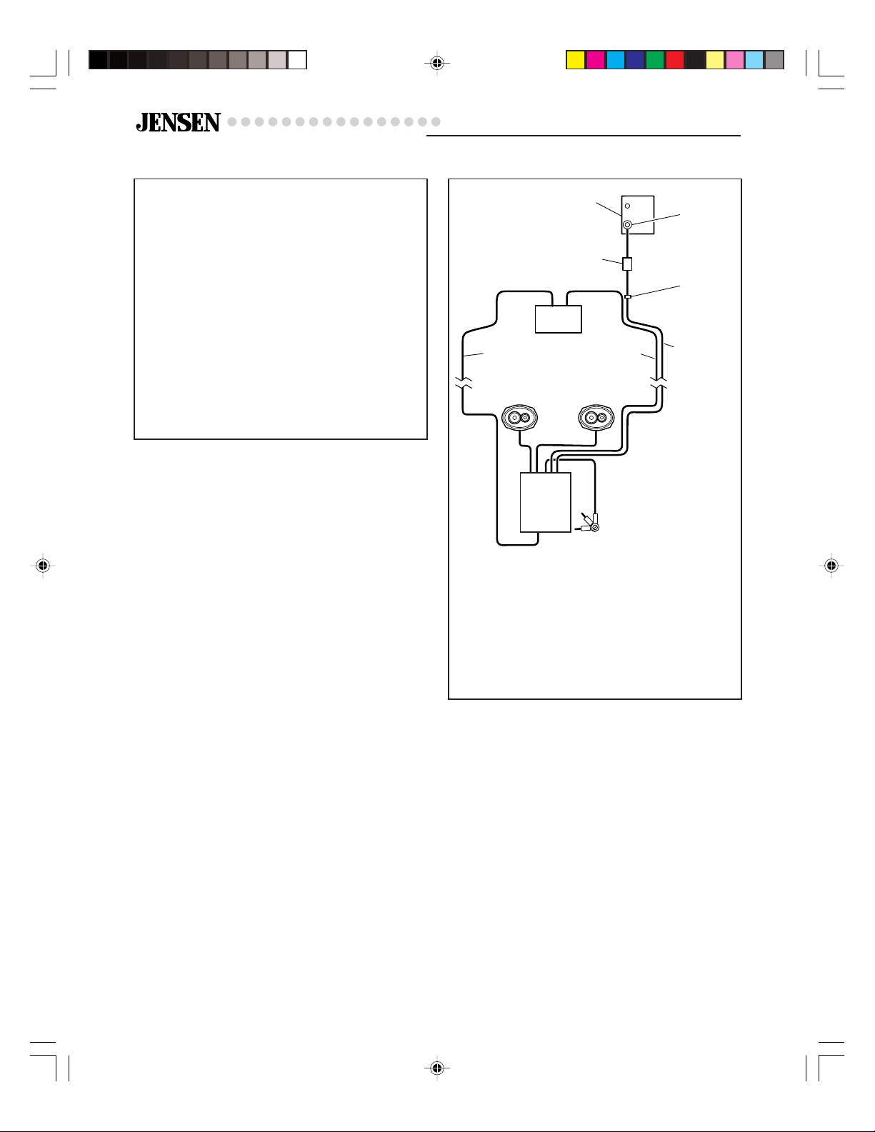
Routing Wires
Location and Mounting
The XA amplifier’s compact design allows
greater flexibility in mounting. It can be
mounted under a seat or in the trunk.
When selecting a location, remember that
amplifiers generate heat. Select a location
where air can circulate around the amplifier.
Do not cover the amplifier with carpets or
enclose it behind interior trim panels. Do not
mount the amplifier in an inverted or upside
down configuration. Every installation will be
a bit different based upon vehicle design.
Check all locations and placements carefully
before making any cuts or connections.
Important
Allow air circulation around the amplifier.
Important
If wiring connections are made wrong, the unit
will not operate properly and it could be
damaged. Follow the installation instructions
carefully, or have the installation handled by
an experienced technician.
Speakers
Battery
Connector
Fuse or
Circuit
Breaker
Battery
Power Wire
(8 gauge
wire or
larger)
Power Antenna
Turn-on Wire
(18 gauge wire)
RCA Cables
Ground Screw
Drill 1/8" hole in
chassis sheet metal
Use the same ground if
using multiple amplifiers
Grommet
To prevent
damage to
power wire
Receiver
Amplifier
6236 XA2CH_E.p65 5/7/01, 2:07 PM4
 Loading...