


JENN-AIR JEC7430AAW, JEC7430AAB, MEC4436AAW, MEC4436AAC, MEC4436AAB Installation Instructions
...IMPORTANT - PLEASE KEEP FOR THE USE OF THE LOCAL ELECTRICAL INSPECTOR
INSTALLATION INSTRUCTIONS
Electric Counter Mounted Surface Units
READ “SAFETY INSTRUCTIONS” IN USE & CARE BOOK BEFORE USING UNIT
In order to assure the best results in service, proper operation and maximum efficiency, the original installation and adjustment should be made by your dealer, his authorized agent, or by your local utility company before you attempt to operate the surface unit.
LOCATION
Place unit where it will be well lighted. For proper cooking results, it must be level. THESE ELECTRIC COUNTER MOUNTED SURFACE UNITS ARE APPROVED FOR INSTALLATION IN COMBUSTIBLE CABINETRY. SEE INSTALLATION DIAGRAM FOR THE APPROPRIATE UNIT ON THE FOLLOWING PAGES OF THIS INSTRUCTION SHEET.
OUTSIDE WIRING
Your local utility company will tell you whether the present electric service to your home is adequate. It may be necessary to increase the size of the wiring to the house and service switch to take care of the electrical load demanded by the surface unit and/or oven. The wattage (K.W. rating) load for the range is specified on the name plate on the unit.
HOUSE WIRING
Most local building regulations and codes require that all electrical wiring be done by licensed electricians. All wiring should conform to Local and National Electrical Codes. This unit requires a single phase three wire 120/240 or a 120/208 volt, 60 Hz, AC circuit. Wiring codes require that a separate circuit be run from the main entrance panel to the unit and that it be equipped with separate disconnect switch and fuses, either in the main entrance panel or in a separate switch and fuse box.
UNIT CONNECTIONS
This unit is supplied with a 240/208 volt wiring system consisting of 2 insulated conductors and 1 bare grounding wire for use on a 3 wire 120/240 or a 120/208 volts, 60 Hz AC branch circuit. Connect only to a 3-wire, 120/240-volt power supply; the neutral conductor is not required for the operation of the appliance. The potential at the power supply electrical connections shall be 150-volts-to-ground or less. The flexible armored conduit supplied with the unit must be connected to an approved electrical junction box by means of an approved conduit to box connector.
THE BARE WIRE IN THE UNIT CONDUIT ISCONNECTED TO THE FRAME OF THE UNIT. THE FRAME OF THE UNIT IS GROUNDED TO NEUTRAL OF THE BRANCH CIRCUIT ONLY WHEN THIS BARE WIRE IS CONNECTED TO THE NEUTRAL (WHITE) WIRE OF THE BRANCH CIRCUIT. If used on new branch-circuit installations (1996 NEC), mobile homes, recreational vehicles, or in an area where local codes prohibit grounding through the neutral conductor, the bare wire at the end of the unit conduit must be used to ground the unit in accordance with local code. The red and black wires must be connected to two conductors (red and black) of the branch circuit. The neutral (white) wire of the branch circuit must be properly insulated. Connect all wires to the branch circuit with approved connectors. Use copper or aluminum wire. If aluminum wire is used, use connectors recognized for joining aluminum to copper.
APPROVED |
|
CONNECTOR |
RANGE CONDUIT |
BLACK |
RED |
APPROVED |
BARE |
BOX |
|
L1 |
APPROVED INSULATED |
|
CONNECTIONS |
NEUTRAL |
L2 |
|
BRANCH CIRCUIT |
|
(POWER SUPPLY) |
RANGE GROUNDED THROUGH NEUTRAL CONDUCTOR
APPROVED |
|
CONNECTOR |
RANGE CONDUIT |
BLACK |
RED |
INSULATED |
BARE |
|
APPROVED BOX |
L1 |
APPROVED INSULATED |
|
|
|
CONNECTIONS |
NEUTRAL |
L2 |
|
BRANCH CIRCUIT |
|
(POWER SUPPLY) |
|
SEPARATE GROUND |
WIRING METHOD IF CODE DOES NOT PERMIT GROUNDING THROUGH NEUTRAL CONDUCTOR & ALSO REQUIRED IN MOBILE HOMES.
WARNING: Be sure UNIT is DISCONNECTED from POWER SUPPLY before examining any of the electrical equipment.
8101P480-60
(05-02-00)

Units shown in figures 1 and 2 may be installed in combustible countertop and must be spaced at least (1 from) combustible sides and rear wall above countertop.
Unit shown in figure 3 may be installed in combustible countertop and adjacent to (0 from) combustible sides and rear wall above countertop.
Dimension A = 30-inches minimum clearance between top of the cooking surface and the bottom of an unprotected wood or metal cabinet, or A = 24-inches minimum when bottom of wood or metal cabinet is protected by not less than 1/4 inch flame retardant millboard covered with not less than no. 28 msg sheet steel, .015 inch stainless steel,
.024 inch aluminum or .020 inch copper.
“To eliminate the hazard of reaching over heated surface units, cabinet storage space located above the surface units should be avoided. If cabinet storage is to be provided, the hazard can be reduced by installing a range hood that projects horizontally a minimum of 5-inches beyond the bottom of the cabinets.”
CAUTION: SOME CABINETS AND BUILDING MATERIALS ARE NOT DESIGNED TO WITHSTAND THE HEAT PRODUCED BY THE NORMAL SAFE OPERATION OF A LISTED APPLIANCE. DISCOLORATION OR DAMAGE, SUCH AS DELAMINATION, MAY OCCUR.
“A”
COUNTER
TOP BASE CABINET
If cooktop is to be secured to countertop, remove main top and attach burner box to countertop at (4) corners.
To remove main top from burner box, remove all (4) surface units and drip bowls. Remove the (4) mounting screws from main top. (Tabs on side of element openings.)
CAUTION: DO NOT REMOVE GREEN GROUND WIRE FROM MAIN TOP. WHEN REPLACING MAIN TOP, USE CAUTION TO BE SURE WIRES ARE NOT PINCHED UNDER SWITCH SHIELD.
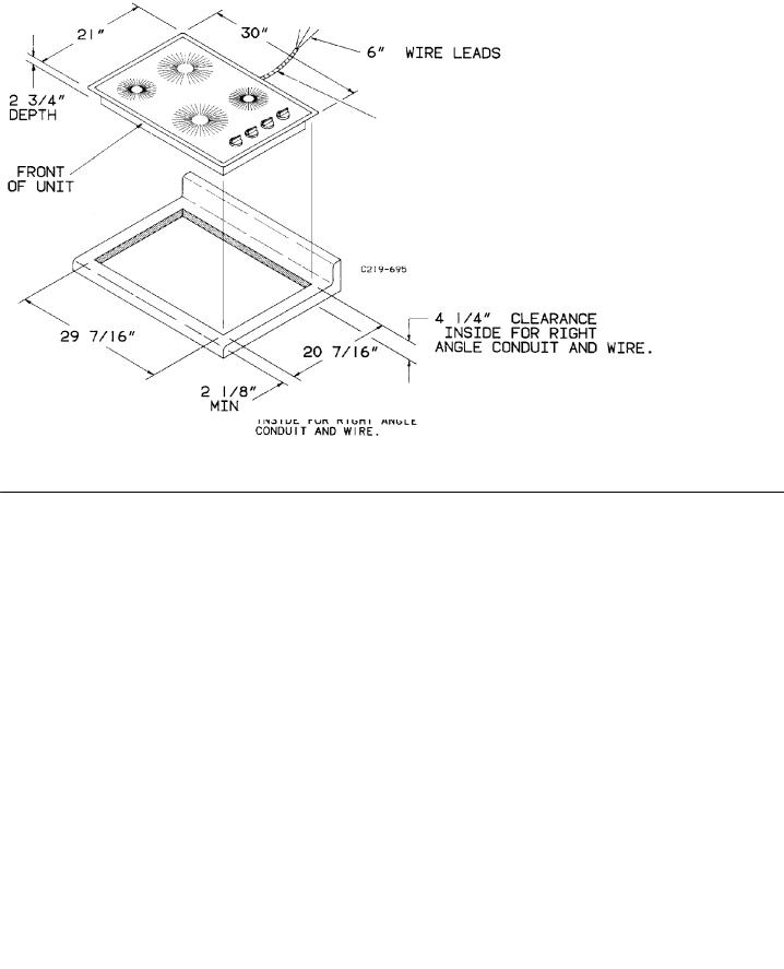
30 Cooktop with Coil Elements
3/8 FLEXIBLE CABLE 3′ MIN.
FURNISHED AND
INSTALLED BY MANUFACTURER (CONNECT TO 240/120-VOLT ELECTRICAL SERVICE.)
FIGURE 1
2
36 Cooktop with Coil Elements
FIGURE 2
30 Smoothtop Ceramic Cooktop
3/8 FLEXIBLE CABLE 48 LONG FURNISHED AND INSTALLED BY MANUFACTURER (CONNECT TO 240/120 VOLT ELECTRICAL SERVICE)
FIGURE 3
3
 Loading...