


JGCP648ADP
8101P546-60
(12-03-01)
SPECIAL WARNING
Improper installation, adjustment, alteration, service, maintenance or use of
appliance can result in serious injury or property damage.
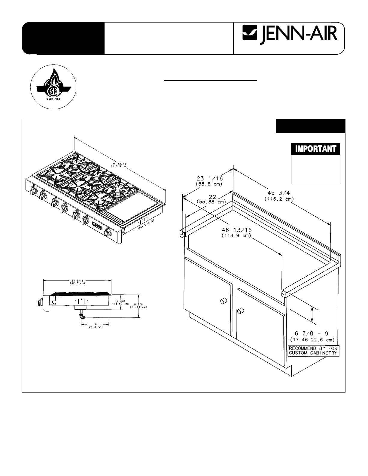
CUTOUT
DIMENSIONS
ARE
CRITICAL
JGCP648ADP
INSTALLATION
INSTRUCTIONS
Prostyle Cooktops
JGCP430ADP, JGCP636ADP,
and JGCP648ADP
403 WEST FOURTH STREET, NORTH D NEWTON, IA 50208
S
SS
S ACCESS MUST BE PROVIDED TO REMOVE AN EMPTY GREASE CONTAINER.
S NOTICE TO INSTALLER: Leave these instructions with the appliance.
S NOTICE TO CONSUMER: Retain these instructions for future reference.
FIGURE 1
2
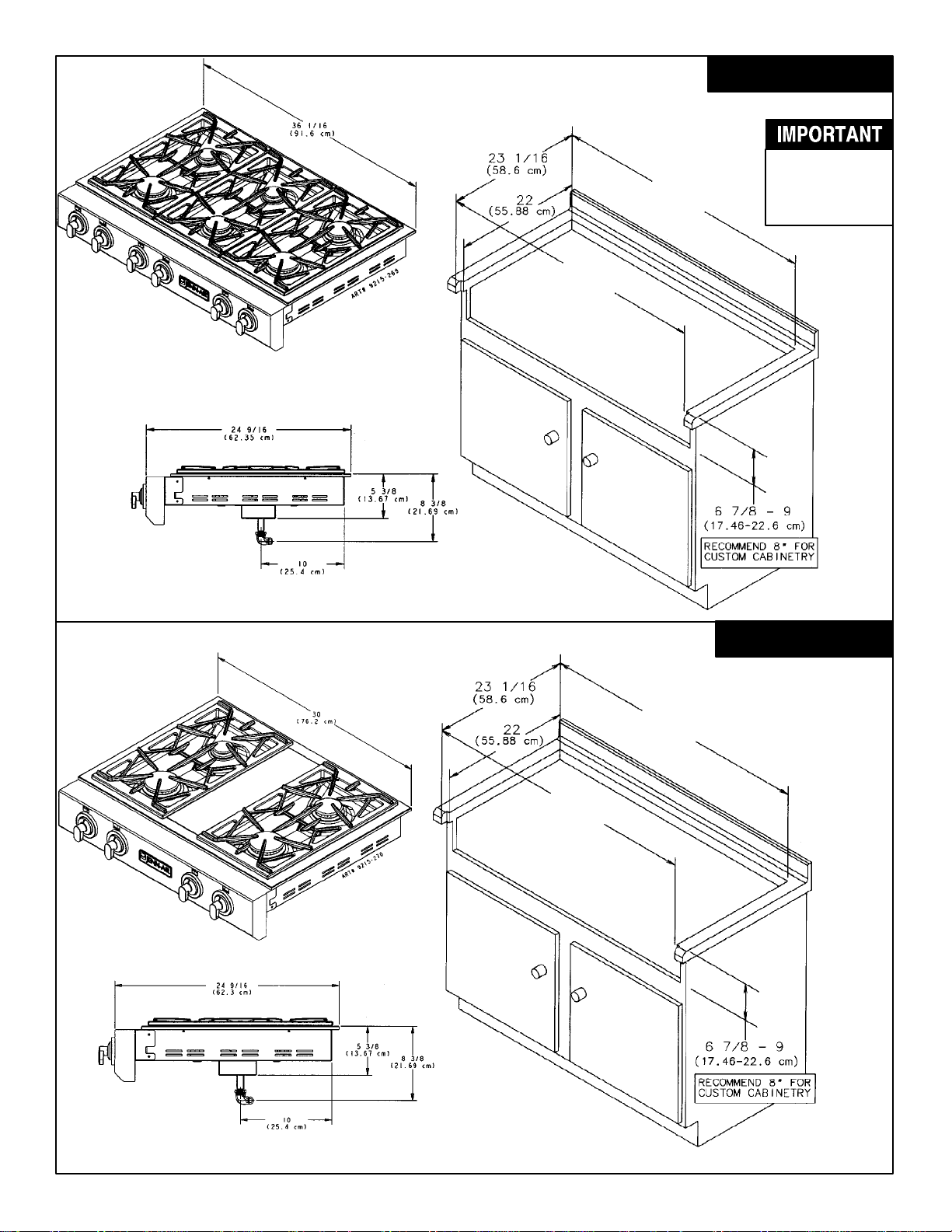
CUTOUT
DIMENSIONS
ARE
CRITICAL
JGCP636ADP
JGCP430ADP
FIGURE 2
FIGURE 3
35 1/16²
(89.06 cm)
36 1/16²
(91.6 cm)
30²
(76.20 cm)
28 15/16²
(72.34 cm)
3
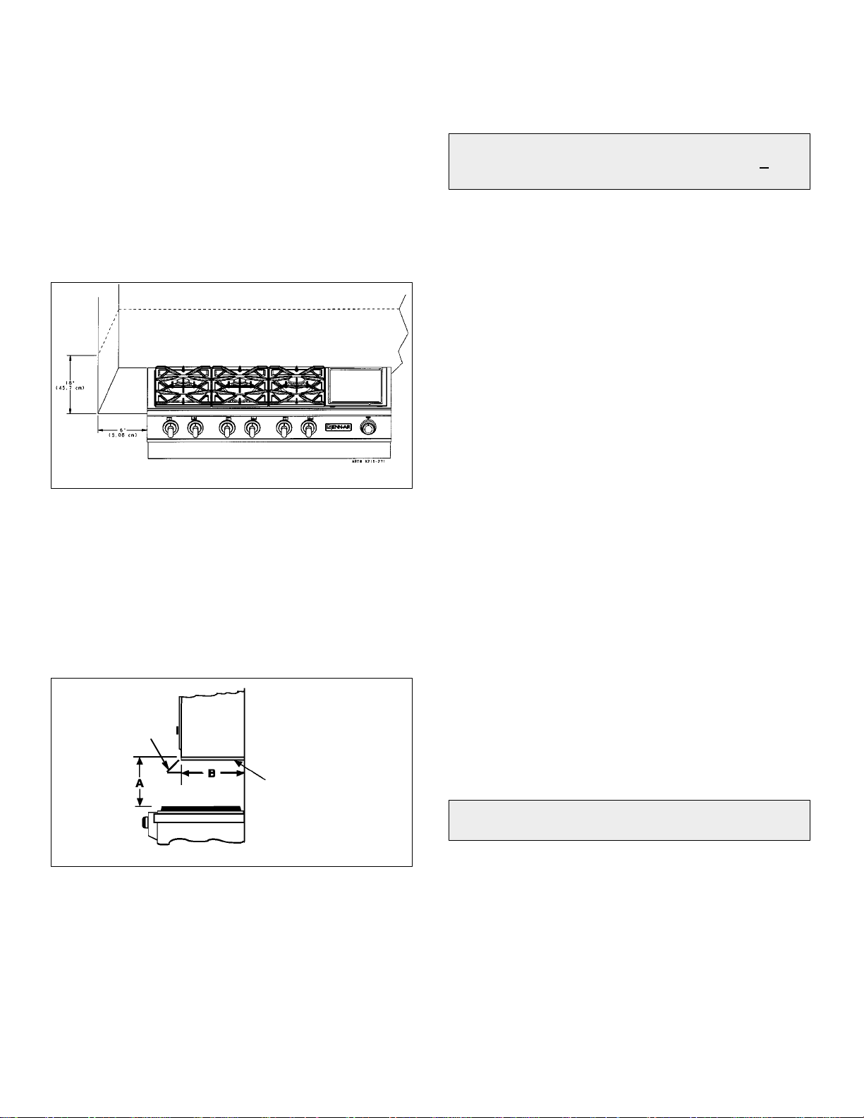
Installing Cabinetry Over Your
Jenn-air Grill
Minimum horizontal clearance between the edge of the
appliance and combustible construction extending from
the cooking surface to 18² (45.7 cm) above the cooking
surface is:
15/16² (2.38 cm) at rear
6² (15.24 cm) at left side
6² (15.24 cm) at right side
NOTE: This is not the recommended clearance, but
minimum allowable clearance.
FIGURE 4
A=30² (76.2 cm) minimum vertical clearance between
cooking surface and construction above the
appliance. the underside of combustible material or
metal cabinets above the cooking top must be
protected with flame retardant millboard not less than
1/4² (0.635 cm) thick.
B=13² (33.02 cm) maximum depth of cabinets installed
above cooking top.
FIGURE 5
Lines indicate
range hood
construction
1/4² THICK FLAME
RETARDANT
MILLBOARD
Avoid use of cabinets above cooktop for storage space to
eliminate associated potential hazards such as reaching
over open flames.
*To eliminate the risk of burns or fire by reaching over
heated surface units, cabinet storage space located
above the surface units should be avoided. If cabinet
storage is to be provided, the risk can be reduced by
installing a range hood that projects horizontally a
minimum of 5 inches beyond the bottom of the cabinets.
Preparation Of Countertop
The countertop cutout must be prepared according to the
illustrations on pages 1 and 2 of these instructions.
CAUTION: Cutout dimensions are critical. Dimensions
must be measured and cut accurately to within +
1/16²
(.159 cm) to ensure proper fit.
Important Preparation Suggestions
1. Chamfer all exposed edges of decorative laminate to
prevent damage from chipping.
2. Radius corners of cutout and file to insure smooth
edges and prevent corner cracking.
3. Rough edges, inside corners which have not been
rounded and forced fits can contribute to cracking of
the countertop laminate.
4. Countertop must be supported within 3² (7.62 cm) of
cutout.
Installation Of Appliance
The installation of this appliance must conform with local
codes or, in the absence of local codes, with the National
Fuel Gas Code, ANSI Z223.1-Latest Edition, or, in
Canada, CAN/CGA-B149 Installation Code, Latest
Edition.
This appliance, when installed, must be electrically
grounded in accordance with local codes or, in the
absence of local codes, with the National Electrical Code
ANSI/NFPA No. 70-Latest Edition, or, in Canada, current
CSA Standard C22.1 Canadian Electrical Code, Part 1.
All supply piping, except as noted, should use common
National Pipe Thread (N.P.T.). For all pipe connections
use an approved pipe joint compound resistant to the
action of LP gas.
CAUTION: Warranty is void on Jenn-Air equipment
installed other than as recommended by manufacturer.
This appliance is designed for use with the appliance gas
pressure regulator supplied with this appliance. It must be
installed in the gasway ahead of the gas manifold
entrance. It is preset for use with natural gas and must be
converted for use with LP gas.
This appliance is designed to operate at a pressure of 5
inches of water column on natural gas or, if converted for
use with LP gas (propane or butane), 10 inches water
column. Make sure this appliance is supplied with and
adjusted for the type of gas for which it is designed.
4
Installation Of Appliance
This appliance was adjusted at the factory for use with
natural gas. If, at any time, this appliance is to be used
with a different type of gas, all of the conversion
adjustments must be made by a qualified service
technician before attempting to operate the cooktop on
that gas. Natural gas should be supplied to the appliance
pressure regulator at a line pressure between 6 and 14
inches of water column or, if converted for LP gas,
between 11 and 14 inches.
If the line pressure supplying the appliance pressure
regulator exceeds 14² W.C. (any gas), an external
regulator must be installed in the gas line ahead of the
appliance regulator to reduce the pressure to no more
than 14² W.C. Failure to do this can result in malfunction
and damage to the appliance.
WARNING
Insure this appliance is adjusted for the type of gas
supplied to it and that the gas supply pressure to the
appliance regulator is within the proper pressure range.
Do not remove protective cap from pipe stub at manifold
entrance until ready to join gas supply piping to appliance.
The Countertop Cutout and Cabinet Front Cutout should
be prepared according to the illustrations on pages 1 and
2.
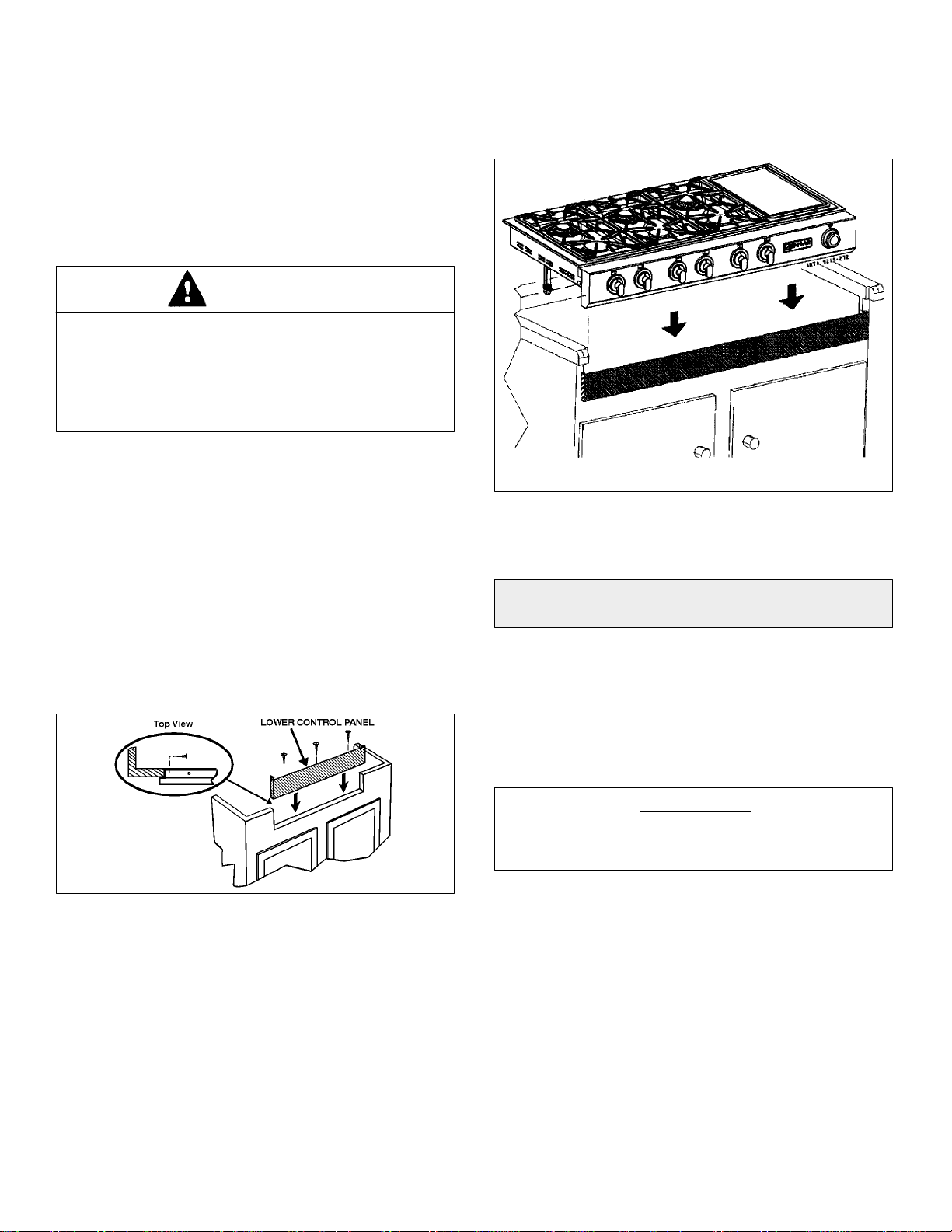
Install the Lower Control Panel in the bottom of the
Cabinet Cutout as shown using screws from Hardware
pack (Figure 6).
FIGURE 6
Position unit in the Countertop Cutout. Main Control Panel
should overlap top of Lower Control Panel as shown
(Figure 7).
FIGURE 7
NOTE: For some cabinet styles, it may be necessary to
reinforce the front of the cabinet by attaching a brace from
front to rear inside the cabinet under the Burner Box.
CAUTION: Warranty is void on JENN-AIR equipment
installed other than as recommended by manufacturer.
Join the appliance pressure regulator supplied with this
appliance to the entrance threads of the Gas Manifold.
The appliance regulator is marked with a directional arrow
indicating correct direction of gas flow. Ensure the
appliance regulator is installed with the arrow pointing
toward the gas manifold entrance. Tighten the appliance
regulator to 20 to 30 ft-lbs of torque.
IMPORTANT
Nevertightento morethan35 ft-lbsof torque.Always use
an approved pipe joint compound resistant to the action
of LP gas.
Install the appliance in its counter cutout.
Make the gas connection to the inlet of the appliance
pressure regulator with 1/2² male pipe threads.
Install a manual shut-off valve in an accessible location in
the gas line ahead of the appliance pressure regulator
and external to this appliance for the purpose of turning
on or shutting off gas to the appliance.
Make additional pipe connections as necessary ahead of
the shut-off valve to the gas supply source. Assure all
pipe joint connections are gas tight.
5
Gas Supply Connection
A TRAINED SERVICEMAN OR GAS APPLIANCE
INSTALLER MUST MAKE THE GAS SUPPLY
CONNECTION. Leak testing of the appliance shall be
conducted by the installer according to the instructions
below.
Apply a non-corrosive leak detection fluid to all joints and
fittings in the gas connection between the supply line
shut-off valve and the range. Include gas fittings and
joints in the range if connections were disturbed during
installation. Check for leaks! Bubbles appearing around
fittings and connections will indicate a leak. If a leak
appears, turn off supply line gas shut-off valve, tighten
connections, turn on the supply line gas shut-off valve,
and retest for leaks.
CAUTION: NEVER CHECK FOR LEAKS WITH A
FLAME.
WHEN LEAK CHECK IS COMPLETE, WIPE OFF
ALL RESIDUE.
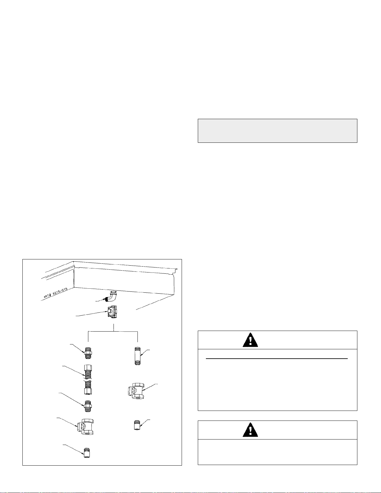
If the alternative piping method shown in figure 8 is
selected for the installation, no ground joint union is
required. (The flexible appliance connector illustrated
provides the union joints necessary for servicing.) When a
dividing wall is present and a flexible connector is used it
is recommended for convenience, in both installation and
service, the flexible connector, itself, pass through the
dividing wall. Any flexible connector used with this
appliance must satisfy all requirements stated in the
text following figure 8.
FIGURE 8
MANIFOLD PIPE
GAS
SHUT-OFF
VALVE
APPLIANCE PRESSURE
REGULATOR, SUPPLIED
(OBSERVE DIRECTION
OF GAS FLOW ARROW)
FLARE
UNION
ADAPTOR
FLEXIBLE
APPLIANCE
CONNECTOR
(5 FT. MAX)
FLARE
UNION
ADAPTOR
1/2² NPT
PIPE
1/2² NPT
PIPE
1/2² NPT
PIPE
NIPPLE
GAS
SHUT-OFF
VALVE
Unless prohibited by local codes or ordinances, a new
A.G.A. - Certified, flexible metal appliance connector may
be used to connect this appliance to its gas supply. The
connector must have an internal diameter not less than
nominal 1/2² NPT pipe and be no more than 5 feet in
length. A 1/2² NPT x 1/2² flare union adapter is required
at each end of the flexible connector. If a flexible
connector is used assure that both the appliance pressure
regulator and manual shut-off valve are joined solidly to
other permanent hard piping (either gas supply or the
appliance manifold) so as to be physically stationary.
CAUTION: Do not attempttoattachthe flexibleconnector
directly to an external pipe thread. Connection requires
flare union adapters.
Pressure Testing
The appliance must be isolated from the gas supply
piping system by closing its individual manual shut-off
valve during any pressure testing of the gas supply piping
system at test pressures equal to or less than 1/2 PSIG
(3.5 kPa).
This appliance, as well as its individual shut-off valve,
must be disconnected from the gas supply piping system
during any pressure testing of the system at test
pressures in excess of 1/2 PSIG (3.5 kPa).
When checking appliance regulator function, make certain
pressure of natural gas supply is between 6 and 14
inches of water column or, if converted for LP gas,
between 11 and 14 inches.
Electrical Wiring Information
This appliance is equipped with a grounded type power
cord. A grounded outlet must be provided.
The power cord extends 45² outside the unit housing. The
outlet should be located inside the cutout width and below
the lowest most projection of the unit housing.
ELECTRICAL GROUNDING INSTRUCTIONS
THIS APPLIANCE IS EQUIPPED WITH A THREE
PRONG GROUNDING PLUG FOR YOUR
PROTECTION AGAINST SHOCK HAZARD AND
SHOULD BE PLUGGED DIRECTLY INTO A
PROPERLY GROUNDED RECEPTACLE. DO NOT
CUT OR REMOVE THE GROUNDING PRONG
FROM THIS PLUG.
WARNING
THIS APPLIANCE MUST BE DISCONNECTED FROM
ITS ELECTRICAL SUPPLY AT THE WALL RECEP-
TACLE BEFORE SERVICING THE APPLIANCE.
WARNING
6
Converting Appliance For Use With LP Gas
Propane conversion is to be performed by a JENN-AIR
AUTHORIZED SERVICER (or other qualified agency)in
accordance with the manufacturer’s instructions and all
codes and requirements of the authority having
jurisdiction. Failure to follow instructions could result in
serious injury or property damage. The qualified agency
performing this work assumes responsibility for this
conversion.
WARNING
Electrical power and gas must be turned
off prior to conversion.
WARNING
This appliance was adjusted at the factory for use with
natural gas. To convert it for use with LP gas (propane or
butane), each of the following modifications must be
performed:
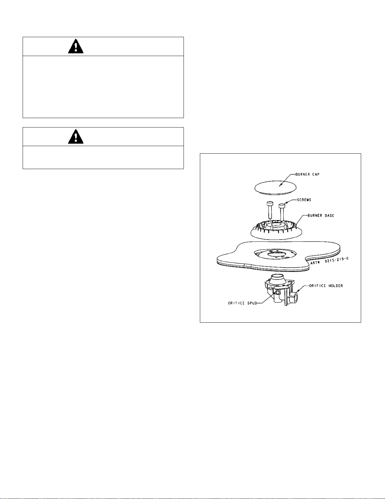
A. Replace all orifice spuds
Step 1: Remove the grates and burner caps.
Step 2: Remove burner base by removing 2 screws.
(See figure 9.)
Step 3: Firmly press 9/32² (or 7mm) nut driver over
the orifice spud (figure 9) and loosen spud by
turning countercloclwise. Carefully lift nut
driver out of burner throat. Orifice spud
should be captured in the recess. Repeat this
step for each burner.
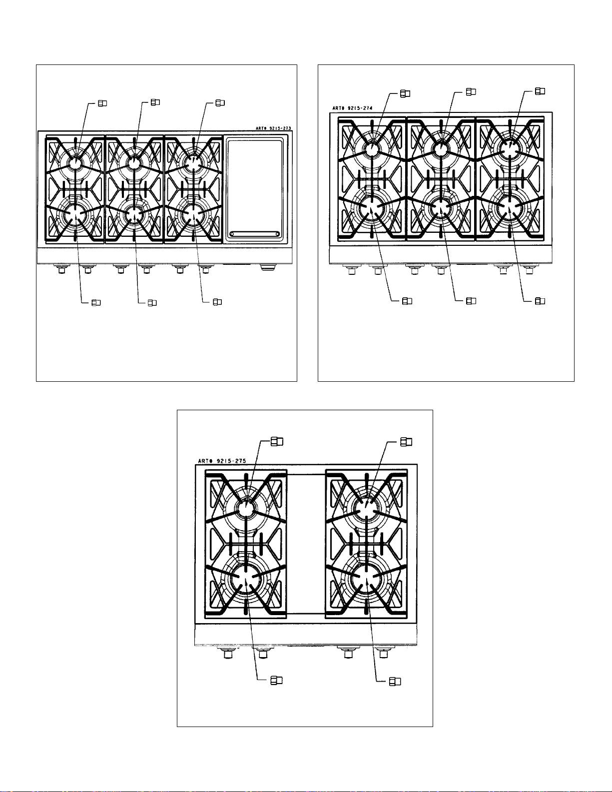
Step 4: Locate the LP orifice spud packet included in
the literature packet. The spuds have small
numbers stamped on the side. This number
codes the orifice diameter and its correct
burner location. Figures on page 7 show the
correct LP orifice spud location.
Step 5: Carefully install the orifice spud in the
appropriate burner throat by turning clockwise
to tighten. Tighten to a torque of 15 to 20
inch-lbs.
Step 6: Replace burner base, caps, and grates.
Tighten screws (do not cross thread) to 25-30
inch-lbs.
Step 7: Save the orifices removed from the appliance
for future use.
FIGURE 9
REMOVAL OF ORIFICE SPUD
7
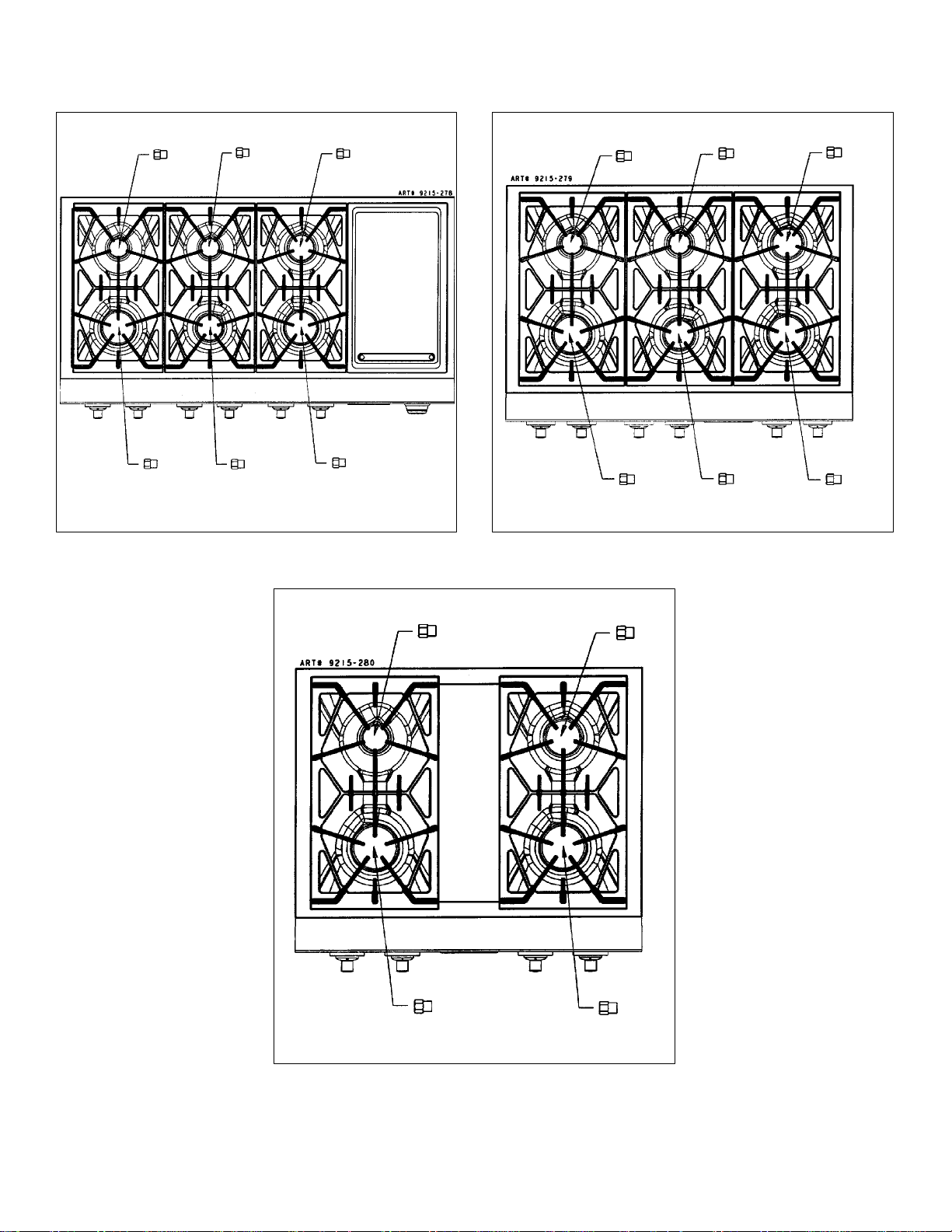
Installation Of LP Orifice Spuds
FIGURE 10
48² MODEL
FIGURE 12
30² MODEL
FIGURE 11
36² MODEL
64
64
95
116 95
116
64
95
116
116
95
116
95
64
64
116
8
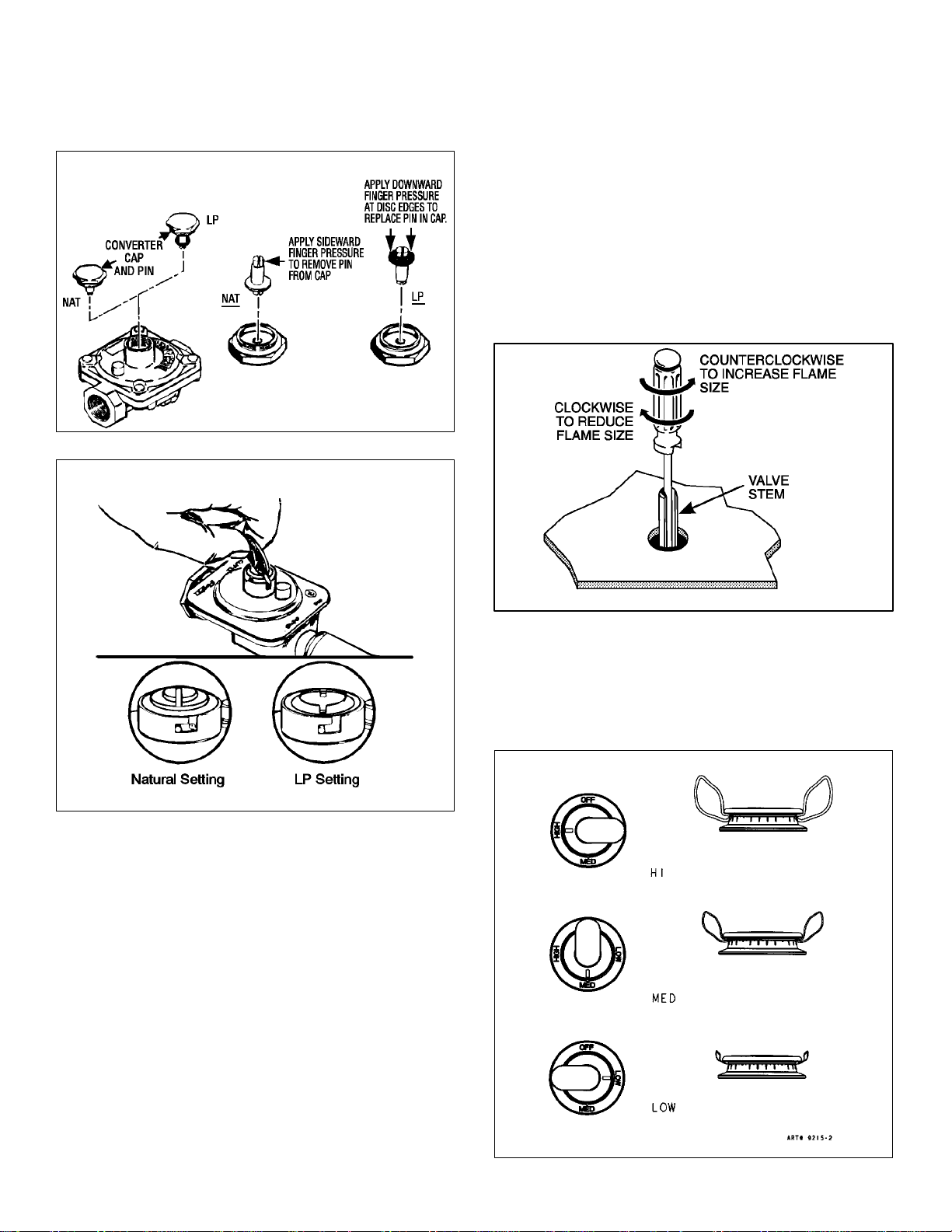
B. Invert cap in appliance pressure regulator
With the appliance installed, identify the type of
appliance regulator on the unit and follow the
instructions in the appropriate illustration.
FIGURE 13
CONVERSION OF MAXITROL APPLIANCE
PRESSURE REGULATOR
FIGURE 14
CONVERSION OF HARPER-WYMAN APPLIANCE
PRESSURE REGULATOR
C. Low Flame Adjustment
This appliance is shipped from the factory with low
and medium flame settings adjusted for use with
natural gas. If further adjustment is necessary, or to
readjust for use with LP, proceed as follows:
1. Light burner and set control knob for low flame.
2. Remove control knob from valve stem.
CAUTION: NEVER USE A METAL BLADE TO PRY
KNOB OFF. IF KNOB CANNOT BE EASILY
REMOVED, TUCK THE FOLDS OF A CLOTH
DISHTOWEL UNDER THE KNOB AND PULL THE
TOWEL OUTWARD WITH STEADY, EVEN
PRESSURE.
3. Insert a slender, thin-blade screwdriver into the
recess at center of valve stem and engage blade
with slot in adjusting screw.
4. Turn center stem adjusting screw to set flame size.
...clockwisetoreduce
...counterclockwise to increase
5. Replace control knob when adjustment is
completed.
Proper adjustment will produce a stable, steady blue
flame of minimum size. The final adjustment should be
checked by turning knob from high to low several times
without extinguishing the flame.
This adjustment, at low setting, will automatically provide
the proper flame size at medium setting.
FIGURE 15
After Conversion Steps A, B and C have been completed,
check the appearance of each burner’s flame at the Hi
and Lo settings against figure 16. If the flames appear too
large or too small, review each step to make sure it was
completed correctly.
FIGURE 16
FLAME APPEARANCE AT HI, MED & LOW

9
To Convert Appliance For Use With Natural Gas
Electrical power and gas must be turned
off prior to conversion.
WARNING
If this appliance has been converted for use with LP gas,
each of the following modifications must be performed to
convert the unit back to natural gas.
A. Replace all orifice spuds
Perform Steps 1 through 3 on page 6.
For Step 4: Locate the colored brass natural gas
orifice spuds that were originally installed in this
appliance before its conversion for use with LP gas.
Observe the color of each of the spuds and note the
correct burner location for each spud as shown on
page 10 figures 17, 18 or 19.
Complete Steps 5, 6, and 7 on page 6 to complete
the installation of natural gas main spuds in their
correct locations.
Save the orifices removed from the appliance for
future use. They will be needed if this appliance is
again converted for use with LP gas.
B. Invert cap in applian ce pressure
regulator.
(See figure 13 or 14.)
With the appliance installed the appliance regulator
should be located as shown in figure 8. Identify the
type of appliance regulator and follow the instructions
in the appropriate illustration.
C. Adjust low flame as instructed on p age 8
item C.
After Steps A, B and C have been completed, check
the appearance of each burner’s flame at the Hi and
Lo settings against figure 16. If the flames appear too
large or too small, make sure all steps were
completed correctly.
10
FIGURE 17
48² MODEL
FIGURE 18
36² MODEL
Installation Of Natural Gas Orifice Spuds
30² MODEL
FIGURE 19
GOLD
BLUE
GOLD
GOLD
RED
RED
BLUE
BLUE
RED
BLUE
BLUE
RED
GOLD
RED
GOLD
GOLD

11
Burner Ignition And
Auto-Reignition
This appliance is equipped for electronic auto-reignition by
means of a spark igniter located at the rear of each
burner. The burners are designed to light at any valve
rotation that admits sufficient gas flow to support a flame
and to automatically relight following a loss of flame due
to a draft or other adverse condition. This feature is
provided as a convenience and is not intended as a safety
feature.
This appliance has no air shutters. Primary air
adjustments are unnecessary. The burners are designed
to provide optimum aeration for all gases without air
shutters. When operating properly, burners should
produce clearly defined, even blue flames. If the flames
have yellow tips or are hazy and otherwise appear to
have insufficient air, obtain the services of a qualified
service technician.
Specified input rates are as shown below.
BURNER
LOCATION Hi Lo
Right Front 17K 1700
Right Rear 9.2K 1050
Left Front 17K 1700
Left Rear 5K 600
INPUT RATES - NATURAL GAS (BTU/HR)
JGCP430ADP
JGCP636ADP and JGCP648ADP
BURNER
LOCATION Hi Lo
Right Front 17K 1700
Right Rear 9.2K 1050
Center Front 9.2K 1050
Center Rear 5K 600
Left Front 17K 1700
Left Rear 5K 600
INPUT RATES - NATURAL GAS (BTU/HR)
Model JGCP648ADP includes 1300 Watt Electric
Griddle Accessory.
Required Adjustments At Time
Of Installation
The installation of this appliance must conform with local
codes, or in the absence of local codes, with the latest
edition of the National Fuel Gas Code ANSI Z223.1 USA
or current CAN/CGA-B149 INSTALLATION CODE.
V This appliance was manufactured for use with Natural
Gas. If LP gas is the fuel of choice, follow the
conversion to LP procedure found in the installation
instructions.
V Test all external connections for gas leaks. Never test
for gas leaks with an open flame.
V Test all electrical connections.
 Loading...