


 Loading...
|
GROUP TAB LOCATOR |
|
|
||
|
|
|
|
|
|
|
|
|
|
|
|
0 |
Maintenance Schedules |
|
|
|
|
|
|
|
|
|
|
7 |
Cooling - 2.5L / 2.8L Diesel |
|
|
|
|
|
|
|
|
|
|
8E |
Electronic Control Modules |
|
|
|
|
|
|
|
|
|
|
8F |
Engine Systems |
|
|
|
|
|
|
|
|
|
|
8I |
Ignition Control |
|
|
|
|
|
|
|
|
|
|
9 |
Engine |
|
|
|
|
|
|
|
|
|
|
11 |
Exhaust System and Turbocharger |
|
|
|
|
|
|
|
|
|
|
14 |
Fuel System |
|
|
|
|
|
|
|
|
|
|
21 |
Automatic Transmission - 545RFE |
|
|
|
|
|
|
|
|||
25 |
Emissions Control - 2.5L / 2.8L Turbo Diesel |
|
|
||
|
|
|
|||
Service Manual Comment Forms |
(Rear of Manual) |
|
|||
|
|
|
|
|
|
KJ |
|
MAINTENANCE SCHEDULES 0 - 1 |
|
MAINTENANCE SCHEDULES
TABLE OF CONTENTS
page
MAINTENANCE SCHEDULES FOR ALL MARKETS EXCEPT U.S., CANADA and MEXICO
DESCRIPTION Ð DIESEL ENGINES . . . . . . . . . 1
MAINTENANCE SCHEDULES FOR ALL MARKETS EXCEPT U.S., CANADA and MEXICO
DESCRIPTION Ð DIESEL ENGINES
Maintenance Schedule Information not included in this section, is located in the appropriate Owner's Manual.
There are two maintenance schedules that show the required service for your vehicle.
First is Schedule ªBº. It is for vehicles that are operated under the conditions that are listed below and at the beginning of the schedule.
²Extensive engine idling.
²Driving in dusty conditions.
²More than 50% of your driving is at sustained high speeds during hot weather, above 32° C (90° F).
²Trailer towing.
²Taxi, police, or delivery service (commercial service).
NOTE: Most vehicles are operated under the conditions listed for Schedule (B(.
Second is Schedule ªAº. It is for vehicles that are not operated under any of the conditions listed under Schedule 9B9.
Use the schedule that best describes your driving conditions. Where time and mileage are listed, follow the interval that occurs first.
CAUTION: Failure to perform the required maintenance items may result in damage to the vehicle.
At Each Stop for Fuel
² Check the engine oil level about 5 minutes after a fully warmed engine is shut off. Checking the oil level while the vehicle is on level ground will improve the accuracy of the oil level reading. Add oil only when the level is at or below the ADD or MIN mark.
² Check the windshield washer solvent and add if required.
Once a Month
²Check the tire pressure and look for unusual wear or damage.
²Inspect the battery and clean and tighten the terminals as required.
²Check the fluid levels of coolant reservoir, brake master cylinder, power steering and transmission and add as needed.
²Check all lights and all other electrical items for correct operation.
At Each Oil Change
²Change the engine oil filter.
²Inspect the exhaust system.
²Inspect the brake hoses.
²Check the manual transmission fluid level Ð if equipped.
²Check the coolant level, hoses, and clamps.
²Inspect engine accessory drive belts. Replace as necessary.
²Inspect for the presence of water in the fuel filter/water separator unit.
²Rotate the tires.
Schedule ªBº
Follow schedule ªBº if you usually operate your vehicle under one or more of the following conditions.
²Extensive engine idling.
²Driving in dusty conditions.
²More than 50% of your driving is at sustained high speeds during hot weather, above 32° C (90° F).
²Trailer towing.
²Taxi, police, or delivery service (commercial service).
0 - 2 MAINTENANCE SCHEDULES |
|
|
|
|
|
|
|
|
|
|
|
KJ |
|
|
|
|
|
|
|
|
|
|
|
|
|||
MAINTENANCE SCHEDULES FOR ALL MARKETS EXCEPT U.S., CANADA and MEXICO (Continued) |
|||||||||||||
|
|
|
|
|
|
|
|
|
|
|
|
|
|
Kilometers |
10 000 km |
20 000 km |
30 000 km |
|
40 000 km |
50 000 km |
|||||||
|
|
|
|
|
|
|
|
|
|
|
|
|
|
Change the engine oil and engine oil filter. |
X |
X |
X |
|
X |
X |
|||||||
|
|
|
|
|
|
|
|
|
|
|
|
|
|
Inspect the ball joints. |
X |
X |
X |
|
X |
X |
|||||||
|
|
|
|
|
|
|
|
|
|
|
|
|
|
Inspect engine accessory drive belt. |
X |
X |
X |
|
X |
|
|
||||||
|
|
|
|
|
|
|
|
|
|
|
|
|
|
Replace engine accessory drive belt. |
|
|
|
|
|
|
|
|
|
X |
|||
|
|
|
|
|
|
|
|
|
|
|
|
|
|
Inspect the engine air filter element. |
X |
|
|
X |
|
|
|
X |
|||||
Replace as necessary. |
|
|
|
|
|
|
|
|
|
|
|
||
|
|
|
|
|
|
|
|
|
|
|
|
|
|
Replace the engine air filter element. |
|
|
X |
|
|
|
X |
|
|
||||
|
|
|
|
|
|
|
|
|
|
|
|
|
|
Replace the engine timing belt. |
|
|
|
|
|
|
|
|
|
X |
|||
|
|
|
|
|
|
|
|
|
|
|
|
|
|
Inspect idler pulleys and timing belt |
|
|
|
|
|
|
|
|
|
X |
|||
tensioner³. |
|
|
|
|
|
|
|
|
|
|
|
||
|
|
|
|
|
|
|
|
|
|
|
|
|
|
Replace fuel filter/water separator unit. |
|
|
X |
|
|
|
X |
|
|
||||
|
|
|
|
|
|
|
|
|
|
|
|
|
|
Inspect the brake linings. |
X |
X |
X |
|
X |
X |
|||||||
|
|
|
|
|
|
|
|
|
|
|
|
|
|
Drain and refill the front and rear axle fluid. |
|
|
X |
|
|
|
X |
|
|
||||
|
|
|
|
|
|
|
|
|
|
|
|
|
|
Drain and refill automatic transmission fluid |
|
|
|
|
|
|
|
|
|
X |
|||
and replace transmission main sump filter. |
|
|
|
|
|
|
|
|
|
|
|
||
|
|
|
|
|
|
|
|
|
|
|
|
|
|
|
|
|
|
|
|
|
|
|
|
|
|
|
|
Kilometers |
|
60 000 km |
|
70 000 km |
|
80 000 km |
|
90 000 km |
|
100 000 km |
|||
|
|
|
|
|
|
|
|
|
|
|
|
|
|
Change the engine oil and engine oil filter. |
|
X |
|
X |
|
X |
|
|
X |
|
X |
||
|
|
|
|
|
|
|
|
|
|
|
|
|
|
Inspect the ball joints. |
|
X |
|
X |
|
X |
|
|
X |
|
X |
||
|
|
|
|
|
|
|
|
|
|
|
|
|
|
Inspect engine accessory drive belt. |
|
X |
|
X |
|
X |
|
|
X |
|
X |
||
|
|
|
|
|
|
|
|
|
|
|
|
|
|
Replace engine accessory drive belt. |
|
|
|
|
|
|
|
|
|
|
X |
||
|
|
|
|
|
|
|
|
|
|
|
|
|
|
Inspect the engine air filter element. |
|
|
|
X |
|
|
|
|
X |
|
|
|
|
Replace as necessary. |
|
|
|
|
|
|
|
|
|
|
|
|
|
|
|
|
|
|
|
|
|
|
|
|
|
|
|
Replace the engine air filter element. |
|
X |
|
|
|
X |
|
|
|
|
X |
||
|
|
|
|
|
|
|
|
|
|
|
|
|
|
Inspect idler pulleys and timing belt |
|
|
|
|
|
|
|
|
|
|
X |
||
tensioner³. |
|
|
|
|
|
|
|
|
|
|
|
|
|
|
|
|
|
|
|
|
|
|
|
|
|
|
|
Replace the engine timing belt. |
|
|
|
|
|
|
|
|
|
|
X |
||
|
|
|
|
|
|
|
|
|
|
|
|
|
|
Inspect the brake linings. |
|
X |
|
X |
|
X |
|
|
X |
|
X |
||
|
|
|
|
|
|
|
|
|
|
|
|
|
|
Drain and refill the front and rear axle fluid. |
|
X |
|
|
|
X |
|
|
|
|
X |
||
|
|
|
|
|
|
|
|
|
|
|
|
|
|
Replace the fuel filter/water separator unit. |
|
X |
|
|
|
X |
|
|
|
|
X |
||
|
|
|
|
|
|
|
|
|
|
|
|
|
|
Drain and refill the transfer case fluid. |
|
|
|
|
|
|
|
|
|
|
X |
||
|
|
|
|
|
|
|
|
|
|
|
|
|
|
Drain and refill the automatic transmission |
|
|
|
|
|
|
|
|
|
|
X |
||
fluid and replace transmission main sump |
|
|
|
|
|
|
|
|
|
|
|
|
|
filter. |
|
|
|
|
|
|
|
|
|
|
|
|
|
|
|
|
|
|
|
|
|
|
|
|
|
|
|
KJ |
|
|
|
|
|
MAINTENANCE SCHEDULES 0 - 3 |
||
|
|
|
|
|
||||
MAINTENANCE SCHEDULES FOR ALL MARKETS EXCEPT U.S., CANADA and MEXICO (Continued) |
||||||||
|
|
|
|
|
|
|
|
|
Kilometers |
110 000 km |
120 000 km |
130 000 km |
140 000 km |
150 000 km |
160 000 km |
||
|
|
|
|
|
|
|
|
|
Change the engine oil and |
X |
X |
X |
|
X |
X |
X |
|
engine oil filter. |
|
|
|
|
|
|
|
|
|
|
|
|
|
|
|
|
|
Inspect the ball joints. |
X |
X |
X |
|
X |
X |
X |
|
|
|
|
|
|
|
|
|
|
Inspect the engine air filter |
X |
|
X |
|
|
X |
|
|
element. Replace as |
|
|
|
|
|
|
|
|
necessary. |
|
|
|
|
|
|
|
|
|
|
|
|
|
|
|
|
|
Replace the engine air filter |
|
X |
|
|
X |
|
X |
|
element. |
|
|
|
|
|
|
|
|
|
|
|
|
|
|
|
|
|
Inspect engine accessory |
X |
X |
X |
|
X |
|
X |
|
drive belt. |
|
|
|
|
|
|
|
|
|
|
|
|
|
|
|
|
|
Replace engine accessory |
|
|
|
|
|
X |
|
|
drive belt. |
|
|
|
|
|
|
|
|
|
|
|
|
|
|
|
|
|
Inspect the idler pulleys and |
|
|
|
|
|
X |
|
|
timing belt tensioner³. |
|
|
|
|
|
|
|
|
|
|
|
|
|
|
|
|
|
Replace the engine timing |
|
|
|
|
|
X |
|
|
belt. |
|
|
|
|
|
|
|
|
|
|
|
|
|
|
|
|
|
Inspect the brake linings. |
X |
X |
X |
|
X |
X |
X |
|
|
|
|
|
|
|
|
|
|
Drain and refill the front and |
|
X |
|
|
X |
|
X |
|
rear axle fluid. |
|
|
|
|
|
|
|
|
|
|
|
|
|
|
|
|
|
Replace the fuel filter/water |
|
X |
|
|
X |
|
X |
|
separator unit. |
|
|
|
|
|
|
|
|
|
|
|
|
|
|
|
|
|
Flush and replace the engine |
|
|
|
|
|
|
X |
|
coolant. |
|
|
|
|
|
|
|
|
|
|
|
|
|
|
|
|
|
Drain and refill automatic |
|
|
|
|
|
X |
|
|
transmission fluid and replace |
|
|
|
|
|
|
|
|
transmission filter (s). |
|
|
|
|
|
|
|
|
|
|
|
|
|
|
|
|
|
Inspection and service should also be performed anytime a malfunction is observed or suspected. Retain all receipts.
³ Replace if there is superficial wear, bearing clearance, or evident grease leak.
0 - 4 MAINTENANCE SCHEDULES |
|
KJ |
|
MAINTENANCE SCHEDULES FOR ALL MARKETS EXCEPT U.S., CANADA and MEXICO (Continued)
Schedule ªAº
Kilometers |
20 000 km |
40 000 km |
60 000 km |
80 000 km |
100 000 km |
|
|
|
|
|
|
Change the engine oil and engine oil |
X |
X |
X |
X |
X |
filter. |
|
|
|
|
|
|
|
|
|
|
|
Inspect the ball joints. |
X |
X |
X |
X |
X |
|
|
|
|
|
|
Inspect the brake linings. |
|
X |
|
X |
|
|
|
|
|
|
|
Inspect the engine air filter element. |
X |
|
X |
|
X |
Replace as necessary. |
|
|
|
|
|
|
|
|
|
|
|
Replace the engine air filter element. |
|
X |
|
X |
|
|
|
|
|
|
|
Inspect the engine accessory drive belt. |
X |
X |
X |
X |
X |
|
|
|
|
|
|
Replace the engine accessory drive |
|
|
|
|
X |
belt. |
|
|
|
|
|
|
|
|
|
|
|
Replace the fuel filter/water separator |
X |
X |
X |
X |
X |
unit. |
|
|
|
|
|
|
|
|
|
|
|
Inspect idler pulleys, and timing belt |
|
|
|
|
X |
tensioner³. |
|
|
|
|
|
|
|
|
|
|
|
Replace the engine timing belt. |
|
|
|
|
X |
|
|
|
|
|
|
Inspect the transfer case fluid. |
|
|
X |
|
|
|
|
|
|
|
|
Kilometers |
120 000 km |
140 000 km |
160 000 km |
180 000 km |
|
|
|
|
|
Change the engine oil and engine oil filter. |
X |
X |
X |
X |
|
|
|
|
|
Inspect the ball joints. |
X |
X |
X |
X |
|
|
|
|
|
Inspect the brake linings. |
X |
|
X |
|
|
|
|
|
|
Inspect the engine accessory drive belt. |
X |
X |
X |
X |
|
|
|
|
|
Inspect the engine air filter element. Replace |
|
X |
|
X |
as necessary. |
|
|
|
|
|
|
|
|
|
Replace the engine air filter element. |
X |
|
X |
|
|
|
|
|
|
Replace the fuel filter/water separator unit. |
X |
X |
X |
X |
|
|
|
|
|
Flush and replace the engine coolant. |
|
|
X |
|
|
|
|
|
|
Inspect the transfer case fluid. |
X |
|
|
|
|
|
|
|
|
Drain and refill the transfer case fluid. |
|
|
|
X |
|
|
|
|
|
Drain and refill automatic transmission fluid |
|
|
X |
|
and replace transmission filter (s). |
|
|
|
|
|
|
|
|
|
Inspection and service should also be performed anytime a malfunction is observed or suspected. Retain all receipts.
³ Replace if there is superficial wear, bearing clearance, or evident grease leak.
WARNING: You can be badly injured working on or around a motor vehicle. Do only that service work for which you have the knowledge and the right equipment. If you have any doubt about your ability to perform a service job, take your vehicle to a competent mechanic.

KJ COOLING - 2.5L/2.8L TURBO DIESEL 7 - 1
COOLING - 2.5L/2.8L TURBO DIESEL
TABLE OF CONTENTS
|
page |
|
page |
COOLING - 2.5L/2.8L TURBO DIESEL |
|
STANDARD PROCEDURE - COOLING |
|
DESCRIPTION - COOLING SYSTEM . . . . . . |
. . . 1 |
SYSTEM - REVERSE FLUSHING . . . . . . . . |
. . . 7 |
DIAGNOSIS AND TESTING |
|
CLEANING . . . . . . . . . . . . . . . . . . . . . . . . . . . |
. . 8 |
DIAGNOSIS AND TESTING - COOLING |
|
INSPECTION . . . . . . . . . . . . . . . . . . . . . . . . . |
. . 8 |
SYSTEM FLOW CHECK . . . . . . . . . . . . . . . |
. . 1 |
SPECIFICATIONS |
|
DIAGNOSIS AND TESTING - COOLING |
|
SPECIFICATIONS - COOLING SYSTEM |
|
SYSTEM AERATION . . . . . . . . . . . . . . . . . . |
. . 1 |
CAPACITY . . . . . . . . . . . . . . . . . . . . . . . . . . |
. . 8 |
DIAGNOSIS AND TESTING - COOLING |
|
SPECIFICATIONS - TORQUE . . . . . . . . . . . |
. . 8 |
SYSTEM LEAK TEST . . . . . . . . . . . . . . . . . . |
. . 2 |
ACCESSORY DRIVE . . . . . . . . . . . . . . . . . . . . . |
. . 9 |
DIAGNOSIS AND TESTING - ON-BOARD |
|
ENGINE . . . . . . . . . . . . . . . . . . . . . . . . . . . . . . |
. 16 |
DIAGNOSTICS (OBD) . . . . . . . . . . . . . . . . . |
. . 2 |
|
|
DIAGNOSIS AND TESTING - COOLING |
|
|
|
SYSTEM . . . . . . . . . . . . . . . . . . . . . . . . . . . |
. . 3 |
|
|
COOLING - 2.5L/2.8L TURBO DIESEL
DESCRIPTION - COOLING SYSTEM
The cooling system regulates engine operating temperature. It allows the engine to reach normal operating temperature as quickly as possible, maintains normal operating temperature and prevents overheating.
The cooling system also provides a means of heating the passenger compartment. The cooling system is pressurized and uses a centrifugal water pump to circulate coolant throughout the system. A separate and remotely mounted, pressurized coolant tank using a pressure/vent cap is used.
COOLING SYSTEM COMPONENTS
The cooling system consists of:
²Charge Air Cooler
²Electric Cooling Fans
²A aluminum-core radiator with plastic side tanks
²A separate pressurized coolant tank
²A pressure/vent cap on the coolant tank
²Fan shroud
²Thermostat
²Coolant
²Low coolant warning lamp
²Coolant temperature gauge
²Water pump
²Hoses and hose clamps
DIAGNOSIS AND TESTING
DIAGNOSIS AND TESTING - COOLING SYSTEM FLOW CHECK
To determine whether coolant is flowing through the cooling system, use the following procedures:
(1) If engine is cold, idle engine until normal operating temperature is reached. Then feel the upper radiator hose. If it is hot, coolant is circulating.
WARNING: DO NOT REMOVE THE COOLING SYSTEM PRESSURE CAP WITH THE SYSTEM HOT AND UNDER PRESSURE BECAUSE SERIOUS BURNS FROM COOLANT CAN OCCUR.
(2) Remove pressure/vent cap when engine is cold, idle engine until thermostat opens, you should observe coolant flow while looking down in the coolant recovery pressure container. Once flow is detected install the pressure/vent cap.
DIAGNOSIS AND TESTING - COOLING SYSTEM AERATION
Low coolant level in a cross flow radiator will equalize in both tanks with engine off. With engine at running and at operating temperature, the high pressure inlet tank runs full and the low pressure outlet tank drops, resulting in cooling system aeration. Aeration will draw air into the water pump resulting in the following:
²High reading shown on the temperature gauge.
²Loss of coolant flow through the heater core.
²Corrosion in the cooling system.
7 - 2 COOLING - 2.5L/2.8L TURBO DIESEL |
|
KJ |
|
COOLING - 2.5L/2.8L TURBO DIESEL (Continued)
²Water pump seal may run dry, increasing the risk of premature seal failure.
²Combustion gas leaks into the coolant can also cause aeration.
DIAGNOSIS AND TESTING - COOLING SYSTEM LEAK TEST
WARNING: THE WARNING WORDS ªDO NOT OPEN HOTº ON THE RADIATOR PRESSURE CAP IS A SAFETY PRECAUTION. WHEN HOT, PRESSURE BUILDS UP IN COOLING SYSTEM. TO PREVENT SCALDING OR INJURY, THE RADIATOR CAP SHOULD NOT BE REMOVED WHILE THE SYSTEM IS HOT OR UNDER PRESSURE.
With engine not running, remove pressure/vent cap from the coolant recovery pressure container and wipe the filler neck sealing seat clean. The coolant level in the recovery pressure container should be full.
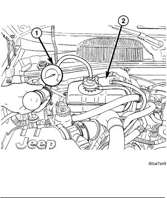
Attach the Cooling System Tester 7700 or equivalent to the radiator, as shown in (Fig. 1) and apply 104 kPa (15 psi) pressure. If the pressure drops more than 13.8 kPa (2 psi) in 2 minutes, inspect all points for external leaks.
All radiator and heater hoses should be shaken while at 104 kPa (15 psi), since some leaks occur only while driving due to engine movement.
If there are no external leaks, after the gauge dial shows a drop in pressure, detach the tester. Start engine and run until the thermostat opens, allowing the coolant to expand. Reattach the cooling system tester. If the needle on the dial fluctuates it indicates a combustion leak, usually a head gasket leak.
WARNING: WITH TOOL IN PLACE, PRESSURE WILL BUILD UP RAPIDLY. EXCESSIVE PRESSURE BUILT UP, BY CONTINUOUS ENGINE OPERATION, MUST BE RELEASED TO A SAFE PRESSURE POINT. NEVER PERMIT PRESSURE TO EXCEED 138 kPa (20 psi).
If the needle on the dial does not fluctuate, raise the engine rpm a few times. If an abnormal amount of coolant or steam emits from the tailpipe, it may indicate a coolant leak caused by a faulty head gasket, cracked engine block, or cracked cylinder head.
There may be internal leaks that can be determined by removing the oil dipstick. If water globules appear intermixed with the oil it will indicate an internal leak in the engine. If there is an internal leak, the engine must be disassembled for repair.
DIAGNOSIS AND TESTING - ON-BOARD DIAGNOSTICS (OBD)
COOLING SYSTEM RELATED DIAGNOSTICS
The Engine Control Module (ECM) has been programmed to monitor certain cooling system components. If the problem is sensed in a monitored circuit often enough to indicated an actual problem, a DTC is stored. The DTC will be stored in the ECM memory for eventual display to the service technician. (Refer to 25 - EMISSIONS CONTROL - DESCRIPTION).
ACCESSING DIAGNOSTIC TROUBLE CODES
To read DTC's and to obtain cooling system data, (Refer to 25 - EMISSIONS CONTROL - DESCRIPTION).
ERASING TROUBLE CODES
After the problem has been repaired, use the DRBIIIt scan tool to erase a DTC. Refer to the appropriate Powertrain Diagnostic Procedures service information for operation of the DRBIIIt scan tool.
Fig. 1 PRESSURE TESTING COOLING SYSTEM
1 - COOLANT PRESSURE TESTER
2 - COOLANT RECOVERY PRESSURE CONTAINER
KJ |
|
COOLING - 2.5L/2.8L TURBO DIESEL 7 - 3 |
|
COOLING - 2.5L/2.8L TURBO DIESEL (Continued)
DIAGNOSIS AND TESTING - COOLING SYSTEM
Establish what driving conditions caused the complaint. Abnormal loads on the cooling system such as the following may be the cause:
(1)PROLONGED IDLE, VERY HIGH AMBIENT TEMPERATURE, SLIGHT TAIL WIND AT IDLE, SLOW TRAFFIC, TRAFFIC JAMS, HIGH SPEED
OR STEEP GRADES.
² Idle with A/C off when temperature gauge is at end of normal range.
(2)TRAILER TOWING:
Consult Trailer Towing section of owners manual. Do not exceed limits.
(3) RECENT SERVICE OR ACCIDENT REPAIR: Determine if any recent service has been performed on vehicle that may effect cooling system.
This may be:
²Engine adjustments (incorrect timing)
²Slipping engine accessory drive belt
²Brakes (possibly dragging)
²Changed parts (incorrect water pump)
²Reconditioned radiator or cooling system refilling (possibly under filled or air trapped in system).
NOTE: If investigation reveals none of the previous items as a cause for an engine overheating complaint, refer to following Cooling System Diagnosis charts.
These charts are to be used as a quick-reference only.
COOLING SYSTEM DIAGNOSIS-DIESEL ENGINE
CONDITION |
POSSIBLE CAUSES |
CORRECTION |
|
|
|
TEMPERATURE GAUGE |
1. Diesel engines, due to their |
1. The low gauge reading may be |
READS LOW |
inherent efficiency are slower to |
normal. Refer to thermostats in the |
|
warm up than gasoline powered |
manual text for information. See |
|
engines, and will operate at lower |
Thermostat Diagnosis-Diesel |
|
temperatures when the vehicle is |
Engine. |
|
unloaded. |
|
|
2. Is the temperature gauge |
2. Check, the engine temperature |
|
connected to the temperature gauge |
sensor connector in the engine |
|
coolant sensor on the engine? |
compartment. |
|
3. Is the temperature gauge |
3. Check gauge operation. Repair |
|
operating OK? |
as necessary. |
|
4. Coolant level low in cold ambient |
4. Check coolant level in the |
|
temperatures accompanied with poor |
coolant tank. Inspect system for |
|
heater performance. |
leaks. Repair leaks as necessary. |
|
|
Refer to the Coolant section for |
|
|
WARNINGS and precautions |
|
|
before removing the pressure cap. |
|
5. Improper operation of internal |
5. Inspect heater and repair as |
|
heater doors or heater controls. |
necessary. Refer to Heating and |
|
|
Air Conditioning for procedures. |
|
|
|
7 - 4 |
COOLING - 2.5L/2.8L TURBO DIESEL |
|
|
KJ |
|
|
|
||||
COOLING - 2.5L/2.8L TURBO DIESEL (Continued) |
|
|
|||
|
|
|
|
|
|
|
CONDITION |
POSSIBLE CAUSES |
CORRECTION |
||
|
|
|
|
|
|
TEMPERATURE GAUGE |
1. Trailer is being towed, a steep hill |
1. This may be a temporary |
|||
READS HIGH. COOLANT |
is being climbed, vehicle is operated |
condition and repair is not |
|||
MAY OR MAY NOT BE LOST |
in slow moving traffic, or engine is |
necessary. Turn off the air |
|||
|
OR LEAKING FROM |
being idled with very high ambient |
conditioning and attempt to drive |
||
|
COOLING SYSTEM |
(outside) temperature and the air |
the vehicle without any of the |
||
|
|
conditioning is on. Higher altitudes |
previous conditions. Observe the |
||
|
|
could aggravate these conditions. |
temperature gauge. The gauge |
||
|
|
|
|
should return to the normal range. |
|
|
|
|
|
If the gauge does not return to |
|
|
|
|
|
normal range, determine the |
|
|
|
|
|
cause for the overheating and |
|
|
|
|
|
repair. |
|
|
|
2. Temperature gauge reading |
2. Check gauge. Refer to I/P |
||
|
|
incorrectly. |
group. |
||
|
|
3. Coolant low in coolant tank and |
3. Check for coolant leaks and |
||
|
|
radiator. |
repair as necessary. |
||
|
|
4. Pressure cap not installed tightly. If |
4. Tighten cap. |
||
|
|
cap is loose, boiling point of coolant |
|
|
|
|
|
will be lowered. |
|
|
|
|
|
5. Poor seals at pressure/vent cap. |
5. (a) Check condition of cap and |
||
|
|
|
|
cap seals. (b) Check condition of |
|
|
|
|
|
coolant tank filler neck. Make sure |
|
|
|
|
|
it does not leak pressure. |
|
|
|
6. Freeze point of antifreeze not |
6. Check antifreeze. Adjust |
||
|
|
correct. Mixture may be too rich. |
antifreeze-to-water ratio as |
||
|
|
|
|
required. |
|
|
|
7. Coolant not flowing through |
7. Check for coolant flow in |
||
|
|
system. |
coolant tank with engine warm and |
||
|
|
|
|
thermostat open. Coolant should |
|
|
|
|
|
be observed flowing through the |
|
|
|
|
|
tank. If flow is not observed, |
|
|
|
|
|
determine reason for lack of flow |
|
|
|
|
|
and repair as necessary. |
|
|
|
8. Radiator or A/C condenser fins are |
8. Clean debris from radiator or |
||
|
|
dirty or clogged. |
A/C condenser |
||
|
|
9. Radiator core is corroded or |
9. Have radiator re-cored or |
||
|
|
plugged. |
replaced. |
||
|
|
10. Aftermarket A/C installed without |
10. Install proper A/C condenser. |
||
|
|
proper A/C condenser. |
|
|
|
|
|
11. Dragging Brakes. |
11. Check and correct as |
||
|
|
|
|
necessary. |
|
|
|
12. Non-factory bug screen is being |
12. Only a factory screen should |
||
|
|
used reducing air flow. |
be used. |
||
|
|
13. Thermostat partially or completely |
13. Check thermostat and replace |
||
|
|
shut. This is more prevalent on high |
if necessary. |
||
|
|
mileage vehicles. |
|
|
|
|
|
14. Cylinder head gasket leaking. |
14. Check cylinder head gasket for |
||
|
|
|
|
leaks. |
|
|
|
15. Heater core leaking. |
15. Check heater core for leaks. |
||
|
|
|
|
Repair as necessary. |
|
|
|
|
|
|
|
KJ |
|
|
COOLING - 2.5L/2.8L TURBO DIESEL 7 - 5 |
|
|
|
|||
COOLING - 2.5L/2.8L TURBO DIESEL (Continued) |
|
|||
|
|
|
|
|
|
CONDITION |
POSSIBLE CAUSES |
CORRECTION |
|
|
|
|
|
|
TEMPERATURE GAUGE |
1. During cold weather operation, |
1. A normal condition. No |
||
READING IS INCONSISTENT |
with the heater blower in the high |
correction is necessary. |
||
(FLUCTUATES, CYCLES OR |
position, the gauge reading may drop |
|
||
|
IS ERRATIC) |
slightly. Fluctuation is also influenced |
|
|
|
|
by loads, outside temperature and |
|
|
|
|
extended idle time with diesel |
|
|
|
|
engines. |
|
|
|
|
2. Temperature gauge or engine |
2. Check operation of gauge and |
|
|
|
mounted gauge sensor defective or |
repair as necessary. |
|
|
|
shorted. Also, corroded or loose |
|
|
|
|
wiring in this circuit. |
|
|
|
|
3. Gauge reading rises when vehicle |
3. A normal condition. No |
|
|
|
is brought to a stop after heavy use |
correction needed. Gauge should |
|
|
|
(engine still running). |
return to normal range after |
|
|
|
|
|
vehicle is driven. |
|
|
4. Gauge reading high after starting a |
4. A normal condition. No |
|
|
|
warm-up (hot) engine. |
correction needed. Gauge should |
|
|
|
|
|
return to normal after a few |
|
|
|
|
minutes of engine operation. |
|
|
5. Coolant level low in the coolant |
5. Check and correct coolant |
|
|
|
tank (air will build up in the cooling |
leaks. |
|
|
|
system causing the thermostat to |
|
|
|
|
open late). |
|
|
|
|
6. Cylinder head gasket leaking |
6. (a) Check for cylinder head |
|
|
|
allowing exhaust gases to enter the |
gasket leaks with a commercially |
|
|
|
cooling system causing the |
available leak tester. (b) Check for |
|
|
|
thermostat to open late. |
coolant in engine oil. Inspect for |
|
|
|
|
|
white steam emitting from exhaust |
|
|
|
|
system. Repair as necessary. |
|
|
7. Water pump impeller loose on |
7. Check water pump and replace |
|
|
|
shaft. |
as necessary. |
|
|
|
8. Loose accessory drive belt (water |
8. Check and correct as |
|
|
|
pump slipping). |
necessary. |
|
|
|
9. Air leak on the suction side of the |
9. Locate leak and repair as |
|
|
|
water pump allowing air to build up in |
necessary. |
|
|
|
the cooling system causing the |
|
|
|
|
thermostat to open late. |
|
|
|
|
|
|
|
|
PRESSURE CAP IS |
1. Pressure relief valve in pressure/ |
1. Check condition of pressure/ |
|
|
BLOWING OFF STEAM |
vent cap is defective. |
vent cap and cap seals. |
|
|
AND/OR COOLANT. |
|
|
|
TEMPERATURE GAUGE |
|
|
|
|
READING MAY BE ABOVE |
|
|
|
|
NORMAL BUT NOT HIGH. |
|
|
|
|
COOLANT LEVEL MAY BE |
|
|
|
|
HIGH IN COOLANT TANK |
|
|
|
|
|
|
2. Head gasket leak or cracked |
2. Repair as necessary. |
|
|
|
cylinder head. |
|
|
|
|
|
|
|
COOLANT LOSS TO THE |
1. Coolant leaks in radiator, cooling |
1. Pressure test cooling system |
||
|
GROUND WITHOUT |
system hoses, water pump, or |
and repair as necessary. |
|
PRESSURE CAP BLOWOFF. |
engine. |
|
||
GAUGE IS READING HIGH |
|
|
|
|
|
OR HOT |
|
|
|
|
|
|
|
|
7 - 6 COOLING - 2.5L/2.8L TURBO DIESEL |
|
|
|
KJ |
|
|
|
|
|||
COOLING - 2.5L/2.8L TURBO DIESEL (Continued) |
|
|
|
||
|
|
|
|
|
|
CONDITION |
POSSIBLE CAUSES |
|
CORRECTION |
||
|
|
|
|
|
|
HOSE OR HOSES |
1. Vacuum created in cooling system |
1. |
Cap relief valve stuck. Replace |
||
COLLAPSE WHEN ENGINE |
on engine cool-down is not being |
if necessary. |
|||
IS COOLING |
relieved through pressure/vent cap. |
|
|
|
|
|
|
|
|
|
|
NOISY FAN |
1. Cooling fan blades loose. |
1. |
Replace cooling fan assembly. |
||
|
2. Cooling fan blades striking a |
2. |
Locate point of fan blade |
||
|
surrounding object. |
contact and repair as necessary. |
|||
|
3. Air obstructions at radiator or A/C |
3. |
Remove obstructions or clean |
||
|
condenser. |
debris from radiator or A/C |
|||
|
|
|
condenser. |
||
|
|
|
|
|
|
INADEQUATE AIR |
1. Radiator and/or A/C condenser is |
1. |
Remove restriction or clean |
||
CONDITIONER |
restricted, obstructed or dirty (insects, |
debris from radiator or A/C |
|||
PERFORMANCE (COOLING |
leaves, etc.) |
condenser. |
|||
SYSTEM SUSPECTED) |
|
|
|
|
|
|
2. Engine is overheating (heat may |
2. |
Correct overheating condition. |
||
|
be transferred from radiator to A/C |
|
|
|
|
|
condenser. High Under hood |
|
|
|
|
|
temperatures due to engine |
|
|
|
|
|
overheating may also transfer heat to |
|
|
|
|
|
A/C condenser). |
|
|
|
|
|
3. The cooling system is equipped |
3. |
Check for missing or damaged |
||
|
with air seals at the radiator and/or |
air seals. Repair as necessary. |
|||
|
A/C condenser. If these seals are |
|
|
|
|
|
missing or damaged, not enough air |
|
|
|
|
|
flow will be pulled through the |
|
|
|
|
|
radiator and A/C condenser. |
|
|
|
|
|
|
|
|
|
|
INADEQUATE HEATER |
1. Diesel engines, due to their |
1. The lower gauge reading may |
|||
PERFORMANCE. MAY BE |
inherent efficiency are slower to |
be normal. |
|||
ACCOMPANIED BY LOW |
warm up than gasoline powered |
|
|
|
|
GAUGE READING |
engines, and will operate at lower |
|
|
|
|
|
temperatures when the vehicle is |
|
|
|
|
|
unloaded. |
|
|
|
|
|
2. Coolant level low. |
2. |
Pressure test cooling system. |
||
|
|
|
Repair leaks as necessary. |
||
|
3. Obstruction in heater hose fitting at |
3. |
Remove heater hoses and |
||
|
engine. |
check for obstructions. Repair as |
|||
|
|
|
necessary. |
||
|
4. Heater hose kinked. |
4. |
Locate kinked area. Repair as |
||
|
|
|
necessary. |
||
|
5. Water pump is not pumping water |
5. |
Refer to water pumps in this |
||
|
to heater core. When the engine is |
group. Repair as necessary. If a |
|||
|
fully warmed up, both heater hoses |
slipping belt is detected, refer to |
|||
|
should be hot to the touch. If only |
Engine Accessory Drive Belts in |
|||
|
one of the hoses is hot the water |
this group. Repair as necessary. |
|||
|
pump may not be operating correctly. |
|
|
|
|
|
The accessory drive belt may also be |
|
|
|
|
|
slipping causing poor water pump |
|
|
|
|
|
operation. |
|
|
|
|
|
|
|
|
|
|
KJ |
|
|
COOLING - 2.5L/2.8L TURBO DIESEL 7 - 7 |
|
|
|
|||
COOLING - 2.5L/2.8L TURBO DIESEL (Continued) |
|
|||
|
|
|
|
|
|
CONDITION |
POSSIBLE CAUSES |
CORRECTION |
|
|
|
|
|
|
|
HEAT ODOR |
1. Various heat shields are used at |
1. Locate missing shields. Repair |
|
|
|
certain drive line components. One or |
or replace as necessary. |
|
|
|
more of these shields may be |
|
|
|
|
missing. |
|
|
|
|
2. Is temperature gauge reading |
2. Refer to the previous |
|
|
|
above the normal range? |
Temperature Gauge Reads High in |
|
|
|
|
|
these Diagnostic Charts. Repair as |
|
|
|
|
necessary. |
|
|
3. Is the Cooling fan operating |
3. Refer to Cooling System Fan in |
|
|
|
correctly? |
this group for diagnosis. Repair as |
|
|
|
|
|
necessary. |
|
|
4. Has undercoating been applied to |
4. Clean undercoating as |
|
|
|
any unnecessary components? |
necessary. |
|
|
|
|
|
|
STEAM IS COMING FROM |
1. During wet weather, moisture |
1. Occasional steam emitting from |
||
FRONT OF VEHICLE NEAR |
(snow, ice, or rain condensation) on |
this area is normal. No repair is |
||
|
GRILL AREA WHEN |
the radiator will evaporate when the |
necessary. |
|
WEATHER IS WET, ENGINE |
thermostat opens. This opening |
|
||
|
IS WARMED UP AND |
allows heated water into the radiator. |
|
|
RUNNING, AND VEHICLE IS |
When the moisture contacts the hot |
|
||
|
STATIONARY. |
radiator, steam may be emitted. This |
|
|
TEMPERATURE GAUGE IS |
usually occurs in cold weather with |
|
||
|
IN NORMAL RANGE |
no fan or air flow to blow it away. |
|
|
|
|
|
|
|
|
COOLANT ODOR |
1. Coolant color is not necessarily an |
1. Refer to Coolant in this group |
|
|
|
indication of adequate corrosion or |
for antifreeze tests. Adjust |
|
|
|
temperature protection. Do not rely |
antifreeze-to-water ratio as |
|
|
|
on coolant color for determining |
necessary. |
|
|
|
condition of coolant. |
|
|
|
|
|
|
|
COOLANT LEVEL CHANGES |
1. Level changes are to be expected |
1. This a normal condition. No |
||
|
IN COOLANT TANK. |
as coolant volume fluctuates with |
repair necessary. |
|
TEMPERATURE GAUGE IS |
engine temperature. If the level in the |
|
||
|
IN NORMAL RANGE |
tank was between the HOT and |
|
|
|
|
COLD marks at normal engine |
|
|
|
|
operating temperature, the level |
|
|
|
|
should return to within that range |
|
|
|
|
after operation at elevated |
|
|
|
|
temperatures. |
|
|
|
|
|
|
|
STANDARD PROCEDURE - COOLING SYSTEM - REVERSE FLUSHING
CAUTION: The cooling system normally operates at 97-to-110 kPa (14-to -16 psi) pressure. Exceeding this pressure may damage the radiator or hoses.
Reverse flushing of the cooling system is the forcing of water through the cooling system. This is done using air pressure in the opposite direction of normal coolant flow. It is usually only necessary with very dirty systems with evidence of partial plugging.
CHEMICAL CLEANING
If visual inspection indicates the formation of sludge or scaly deposits, use a radiator cleaner (Mopar Radiator Kleen or equivalent) before flushing. This will soften scale and other deposits and aid the flushing operation.
CAUTION: Be sure instructions on the container are followed.
REVERSE FLUSHING RADIATOR
Disconnect the radiator hoses from the radiator fittings. Attach a section of radiator hose to the radiator bottom outlet fitting and insert the flushing gun. Connect a water supply hose and air supply hose to the flushing gun.
7 - 8 COOLING - 2.5L/2.8L TURBO DIESEL |
|
KJ |
|
COOLING - 2.5L/2.8L TURBO DIESEL (Continued)
CAUTION: The cooling system normally operates at 97-to-110 kPa (14- to-16 psi) pressure. Exceeding this pressure may damage the radiator or hoses.
Allow the radiator to fill with water. When radiator is filled, apply air in short blasts allowing radiator to refill between blasts. Continue this reverse flushing until clean water flows out through rear of radiator cooling tube passages. For more information, refer to operating instructions supplied with flushing equipment. Have radiator cleaned more extensively by a radiator repair shop.
REVERSE FLUSHING ENGINE
Drain the cooling system (Refer to 7 - COOLING - STANDARD PROCEDURE). Disconnect the radiator upper hose from the radiator and attach the flushing gun to the hose. Disconnect the radiator lower hose from the water pump. Attach a lead away hose to the water pump inlet fitting.
CAUTION: Be sure that the heater control valve is closed (heat off). This is done to prevent coolant flow with scale and other deposits from entering the heater core.
Connect the water supply hose and air supply hose to the flushing gun. Allow the engine to fill with water. When the engine is filled, apply air in short blasts, allowing the system to fill between air blasts. Continue until clean water flows through the lead away hose. For more information, refer to operating instructions supplied with flushing equipment.
Remove the lead away hose, flushing gun, water supply hose and air supply hose. Remove the thermostat housing (Refer to 7 - COOLING/ENGINE/ENGINE COOLANT THERMOSTAT - REMOVAL). Install the thermostat and housing with a replace-
ment gasket (Refer to 7 - COOLING/ENGINE/ENGINE COOLANT THERMOSTAT - INSTALLATION). Connect the radiator hoses. Refill the cooling system with the correct antifreeze/water mixture (Refer to 7 - COOLING - STANDARD PROCEDURE).
CLEANING
Drain cooling system and refill with clean water. Refer to procedures in this section. Run engine with pressure/vent cap installed until upper radiator hose is hot. Stop engine and drain water from system. If water is dirty; fill, run, and drain system again, until water runs clear.
INSPECTION
After performing a cleaning/flush procedure, inspect all hoses, clamps and connections for deterioration and leaks. Inspect radiator and heater core for leaks.
SPECIFICATIONS
SPECIFICATIONS - COOLING SYSTEM CAPACITY
SPECIFICATIONS
DESCRIPTION |
SPECIFICATION |
|
|
Cooling System With |
16.6 Liters (17.5 qts.) |
Auxiliary Heater |
|
|
|
Cooling System With Out |
13.8 Liters (14.6 qts.) |
Auxiliary Heater |
|
|
|
SPECIFICATIONS - TORQUE
2.5L/2.8L DIESEL - TORQUE SPECIFICATIONS
DESCRIPTION |
N´m |
Ft. Lbs. |
In. Lbs. |
|
|
|
|
Accessory Drive Belt Idler |
53 |
39 |
Ð |
Bolt |
|
|
|
|
|
|
|
Accessory Drive Belt |
47.1 |
35 |
Ð |
Tensioner Bolt |
|
|
|
|
|
|
|
Cooling Fan Support Bolts |
47.1 |
35 |
Ð |
|
|
|
|
Thermostat Housing Bolts |
27.5 |
21 |
Ð |
|
|
|
|
Water Pump Housing Nuts |
24.4 |
18 |
215 |
|
|
|
|

KJ |
|
ACCESSORY DRIVE 7 - 9 |
|
ACCESSORY DRIVE
TABLE OF CONTENTS
page
ACCESSORY DRIVE
SPECIFICATIONS - ACCESSORY BELT
TENSION . . . . . . . . . . . . . . . . . . . . . . . . . . . . . 9
BELT TENSIONERS
DESCRIPTION . . . . . . . . . . . . . . . . . . . . . . . . . . 9 OPERATION . . . . . . . . . . . . . . . . . . . . . . . . . . . . 9 REMOVAL . . . . . . . . . . . . . . . . . . . . . . . . . . . . . 10 INSTALLATION . . . . . . . . . . . . . . . . . . . . . . . . . 10
DRIVE BELT
DESCRIPTION
|
page |
OPERATION-ACCESSORY DRIVE BELT . . . . |
. . 11 |
DIAGNOSIS AND TESTING - ACCESSORY |
|
DRIVE BELT . . . . . . . . . . . . . . . . . . . . . . . |
. . 11 |
REMOVAL . . . . . . . . . . . . . . . . . . . . . . . . . . . |
. . 13 |
INSTALLATION . . . . . . . . . . . . . . . . . . . . . . . . |
. 13 |
IDLER PULLEYS |
|
REMOVAL . . . . . . . . . . . . . . . . . . . . . . . . . . . . |
. 14 |
INSTALLATION . . . . . . . . . . . . . . . . . . . . . . . . |
. 15 |
ACCESSORY DRIVE
SPECIFICATIONS - ACCESSORY BELT TENSION
ACCESSORY DRIVE |
GAUGE |
BELT |
|
|
|
2.5L/2.8L DIESEL ENGINE
A/C Compressor/
Dynamic Tensioner
Generator
Power Steering Belt |
Dynamic Tensioner |
BELT TENSIONERS
DESCRIPTION
This engine is equipped with a spring loaded automatic belt tensioner (Fig. 1). This tensioner maintains constant belt tension at all times and requires no maintenance or adjustment.
CAUTION: Do not attempt to check belt tension with a belt tension gauge on vehicles equipped with an automatic belt tensioner.
OPERATION
WARNING: THE AUTOMATIC BELT TENSIONER ASSEMBLY IS SPRING LOADED. DO NOT ATTEMPT TO DISASSEMBLE THE TENSIONER ASSEMBLY.
Fig. 1 ACCESSORY BELT ROUTING
1 - IDLER PULLEY
2 - GENERATOR
3 - IDLER PULLEY
4 - A/C COMPRESSOR
5 - COOLING FAN SUPPORT
6 - VIBRATION DAMPER
7 - BELT TENSIONER
8 - POWER STEERING PUMP
9 - ACCESSORY DRIVE BELT
10 - VISCOUS HEATER
7 - 10 ACCESSORY DRIVE
BELT TENSIONERS (Continued)
The automatic belt tensioner maintains correct belt tension using a coiled spring within the tensioner housing. The spring applies pressure to the tensioner arm pressing the arm into the belt, tensioning the belt.
If a new belt is being installed, the arrow must be within approximately 3 mm (1/8 in.) of indexing mark. Belt is considered new if it has been used 15 minutes or less. If this specification cannot be met, check for:
²The wrong belt being installed (incorrect length/ width)
²Worn bearings on an engine accessory (A/C compressor, power steering pump, water pump, idler pulley or generator)
²A pulley on an engine accessory being loose
²Misalignment of an engine accessory
²Belt incorrectly routed.
REMOVAL
(1) Disconnect negative battery cable.
Fig. 2 ACCESSORY BELT ROUTING
1 - IDLER PULLEY
2 - GENERATOR
3 - IDLER PULLEY
4 - A/C COMPRESSOR
5 - COOLING FAN SUPPORT
6 - VIBRATION DAMPER
7 - BELT TENSIONER
8 - POWER STEERING PUMP
9 - ACCESSORY DRIVE BELT
10 - VISCOUS HEATER
KJ
(2)Remove accessory drive belt (Fig. 2)(Refer to 7 - COOLING/ACCESSORY DRIVE/DRIVE BELTS - REMOVAL).
(3)Remove belt tensioner retaining bolt and remove tensioner from bracket (Fig. 3).
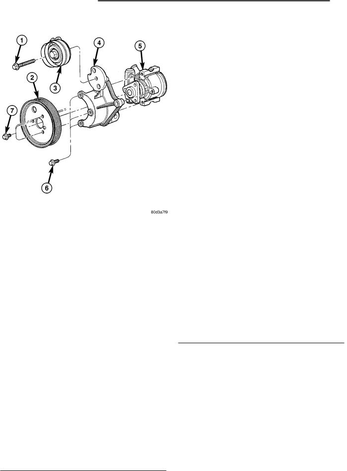
Fig. 3 BELT TENSIONER ASSEMBLY
1 - ACCESSORY BELT TENSIONER RETAINING BOLT
2 - POWER STEERING PUMP PULLEY
3 - BELT TENSIONER
4 - BRACKET
5 - POWER STEERING PUMP
6 - POWER STEERING PUMP RETAINING BOLTS
7 - POWER STEERING PUMP PULLEY RETAINING BOLTS
INSTALLATION
(1)Install belt tensioner on bracket (Fig. 3). Torque retaining bolt to 47.1N´m.
(2)Install accessory drive belt (Fig. 2)(Refer to 7 - COOLING/ACCESSORY DRIVE/DRIVE BELTS - INSTALLATION).
(3)Connect negative battery cable.

KJ
DRIVE BELT
DESCRIPTION
The accessory drive belt is a serpentine type belt (Fig. 4). Satisfactory performance of these belts depends on belt condition and proper belt tension.
Fig. 4 ACCESSORY BELT ROUTING
1 - IDLER PULLEY
2 - GENERATOR
3 - IDLER PULLEY
4 - A/C COMPRESSOR
5 - COOLING FAN SUPPORT
6 - VIBRATION DAMPER
7 - BELT TENSIONER
8 - POWER STEERING PUMP
9 - ACCESSORY DRIVE BELT
10 - VISCOUS HEATER
OPERATION-ACCESSORY DRIVE BELT
ACCESSORY DRIVE 7 - 11
DIAGNOSIS AND TESTING - ACCESSORY DRIVE BELT
VISUAL DIAGNOSIS
When diagnosing serpentine accessory drive belts, small cracks that run across the ribbed surface of the belt from rib to rib (Fig. 5), are considered normal. These are not a reason to replace the belt. However, cracks running along a rib (not across) are not normal. Any belt with cracks running along a rib must be replaced (Fig. 5). Also replace the belt if it has excessive wear, frayed cords or severe glazing.
Refer to ACCESSORY DRIVE BELT DIAGNOSIS CHART for further belt diagnosis.
Fig. 5 BELT WEAR PATTERN
1 - NORMAL CRACKS BELT OK
2 - NOT NORMAL CRACKS REPLACE BELT
NOISE DIAGNOSIS
Noises generated by the accessory drive belt are most noticeable at idle. Before replacing a belt to resolve a noise condition, inspect all of the accessory drive pulleys for alignment, glazing, or excessive end play.
The accessory drive belts form the link between the engine crankshaft and the engine driven accessories.

7 - 12 ACCESSORY DRIVE KJ
DRIVE BELT (Continued)
ACCESSORY DRIVE BELT DIAGNOSIS CHART
CONDITION |
|
POSSIBLE CAUSES |
|
CORRECTION |
|
|
|
|
|
RIB CHUNKING (One or more ribs |
1. Foreign objects imbedded in |
1. |
Remove foreign objects from |
|
has separated from belt body) |
pulley grooves. |
pulley grooves. Replace belt. |
||
|
2. |
Installation damage |
2. |
Replace belt |
|
|
|
|
|
RIB OR BELT WEAR |
1. Pulley misaligned |
1. |
Align pulley(s) |
|
|
2. Abrasive environment |
2. |
Clean pulley(s). Replace belt if |
|
|
|
|
necessary |
|
|
3. |
Rusted pulley(s) |
3. |
Clean rust from pulley(s) |
|
4. |
Sharp or jagged pulley groove |
4. |
Replace pulley. Inspect belt. |
|
tips |
|
|
|
|
5. |
Belt rubber deteriorated |
5. |
Replace belt |
|
|
|
|
|
BELT SLIPS |
1. Belt slipping because of |
1. |
Inspect/Replace tensioner if |
|
|
insufficient tension |
necessary |
||
|
2. |
Belt or pulley exposed to |
2. |
Replace belt and clean pulleys |
|
substance that has reduced friction |
|
|
|
|
(belt dressing, oil, ethylene glycol) |
|
|
|
|
3. |
Driven component bearing failure |
3. |
Replace faulty component or |
|
(seizure) |
bearing |
||
|
4. |
Belt glazed or hardened from |
4. |
Replace belt. |
|
heat and excessive slippage |
|
|
|
|
|
|
|
|
LONGITUDAL BELT CRACKING |
1. Belt has mistracked from pulley |
1. |
Replace belt |
|
|
groove |
|
|
|
|
2. |
Pulley groove tip has worn away |
2. |
Replace belt |
|
rubber to tensile member |
|
|
|
|
|
|
|
|
9GROOVE JUMPING9 |
1. Incorrect belt tension |
1. |
Inspect/Replace tensioner if |
|
(Belt does not maintain correct |
|
|
necessary |
|
position on pulley) |
2. |
Pulley(s) not within design |
2. |
Replace pulley(s) |
|
||||
|
tolerance |
|
|
|
|
3. |
Foreign object(s) in grooves |
3. |
Remove foreign objects from |
|
|
|
grooves |
|
|
4. |
Pulley misalignment |
4. |
Align component |
|
5. |
Belt cordline is broken |
5. |
Replace belt |
|
|
|
|
|
BELT BROKEN |
1. Incorrect belt tension |
1. |
Replace Inspect/Replace |
|
(Note: Identify and correct problem |
|
|
tensioner if necessary |
|
before new belt is installed) |
2. Tensile member damaged during |
2. |
Replace belt |
|
|
||||
|
belt installation |
|
|
|
|
3. |
Severe misalignment |
3. |
Align pulley(s) |
|
4. |
Bracket, pulley, or bearing failure |
4. |
Replace defective component |
|
|
|
and belt |
|
|
|
|
|
|
KJ |
|
|
|
|
|
ACCESSORY DRIVE 7 - 13 |
|
|
|
|
|
|
|||
DRIVE BELT (Continued) |
|
|
|
|
|
||
|
|
|
|
|
|
|
|
|
CONDITION |
|
POSSIBLE CAUSES |
|
|
CORRECTION |
|
|
|
|
|
|
|
|
|
NOISE |
1. |
Incorrect belt tension |
1. |
Inspect/Replace tensioner if |
|||
(Objectionable squeal, squeak, or |
|
|
necessary |
||||
rumble is heard or felt while drive |
2. |
Bearing noise |
2. |
Locate and repair |
|||
belt is in operation) |
|||||||
|
|
|
|
|
|||
|
|
3. |
Belt misalignment |
3. Align belt/pulley(s) |
|||
|
|
4. |
Belt to pulley mismatch |
4. |
Install correct belt |
||
|
|
5. |
Driven component induced |
5. |
Locate defective driven |
||
|
|
vibration |
component and repair |
||||
|
|
|
|
|
|
||
TENSION SHEETING FABRIC |
1. Tension sheeting contacting |
1. |
Correct rubbing condition |
||||
FAILURE |
stationary object |
|
|
|
|||
(Woven fabric on outside, |
2. |
Excessive heat causing woven |
2. |
Replace belt |
|||
circumference of belt has cracked or |
|||||||
fabric to age |
|
|
|
||||
separated from body of belt) |
|
|
|
||||
|
|
|
|
|
|||
|
|
3. Tension sheeting splice has |
3. |
Replace belt |
|||
|
|
fractured |
|
|
|
||
|
|
|
|
|
|
|
|
CORD EDGE FAILURE |
1. |
Incorrect belt tension |
1. |
Inspect/Replace tensioner if |
|||
(Tensile member exposed at edges |
|
|
necessary |
||||
of belt or separated from belt body) |
2. |
Belt contacting stationary object |
2. |
Replace belt |
|||
|
|
||||||
|
|
3. |
Pulley(s) out of tolerance |
3. |
Replace pulley |
||
|
|
4. |
Insufficient adhesion between |
4. |
Replace belt |
||
|
|
tensile member and rubber matrix |
|
|
|
||
|
|
|
|
|
|
|
|
REMOVAL
NOTE: The belt routing schematics are published from the latest information available at the time of publication. If anything differs between these schematics and the Belt Routing Label, use the schematics on Belt Routing Label. This label is located in the engine compartment.
CAUTION: DO NOT LET TENSIONER ARM SNAP BACK TO THE FREEARM POSITION, SEVERE DAMAGE MAY OCCUR TO THE TENSIONER.
Belt tension is not adjustable. Belt adjustment is maintained by an automatic (spring loaded) belt tensioner.
(1)Disconnect negative battery cable.
(2)Rotate belt tensioner until it contacts its stop. Remove belt, then slowly rotate the tensioner into the freearm position.
INSTALLATION
NOTE: The belt routing schematics are published from the latest information available at the time of publication. If anything differs between these schematics and the Belt Routing Label, use the schematics on Belt Routing Label. This label is located in the engine compartment.
Belt tension is not adjustable. Belt adjustment is maintained by an automatic ( spring load ) belt tensioner.
(1) Check condition of all pulleys.
CAUTION: When installing the serpentine accessory drive belt, the belt MUST be routed correctly. If not, the engine may overheat due to the water pump rotating in the wrong direction.
7 - 14 ACCESSORY DRIVE
DRIVE BELT (Continued)
(2) Install new belt. Route the belt around all pulleys except the idler pulley (Fig. 6). Rotate the tensioner arm until it contacts its stop position. Route the belt around the idler and slowly let the tensioner rotate into the belt. Make sure the belt is seated onto all pulleys (Fig. 6).
Fig. 6 ACCESSORY BELT ROUTING
1 - IDLER PULLEY
2 - GENERATOR
3 - IDLER PULLEY
4 - A/C COMPRESSOR
5 - COOLING FAN SUPPORT
6 - VIBRATION DAMPER
7 - BELT TENSIONER
8 - POWER STEERING PUMP
9 - ACCESSORY DRIVE BELT
10 - VISCOUS HEATER
KJ
IDLER PULLEYS
REMOVAL
CAUTION: The retaining bolts on the idler pulleys are left hand thread.
(1)Disconnect negative battery cable.
(2)Remove accessory drive belt (Refer to 7 - COOLING/ACCESSORY DRIVE/DRIVE BELTS - REMOVAL).
(3)Remove idler pulley retaining bolts and pulleys (Fig. 7) (Fig. 8).
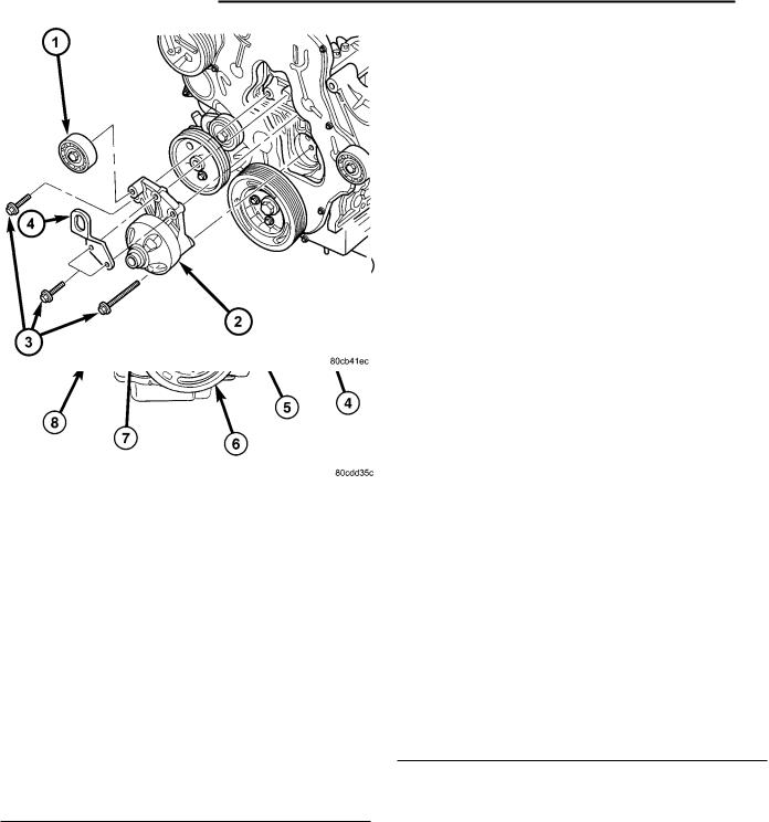
Fig. 7 COOLING FAN SUPPORT
1 - IDLER PULLEY
2 - COOLING FAN SUPPORT
3 - RETAINING BOLTS
4 - ENGINE LIFT HOOK
KJ |
|
ACCESSORY DRIVE 7 - 15 |
|
IDLER PULLEYS (Continued)
INSTALLATION
(1) Install idler pulleys and retaining bolts (Fig. 7) (Fig. 8). Torque bolts to 53N´m.
(2) Install accessory drive belt (Refer to 7 - COOLING/ACCESSORY DRIVE/DRIVE BELTS - INSTALLATION).
(3) Connect negative battery cable.
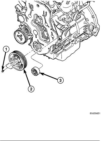
Fig. 8 VIBRATION DAMPER AND IDLER PULLEY
1 - VIBRATION DAMPER/CRANKSHAFT PULLEY RETAINING BOLTS
2 - VIBRATION DAMPER/CRANKSHAFT PULLEY
3 - IDLER PULLEY
7 - 16 ENGINE |
|
KJ |
|
ENGINE
TABLE OF CONTENTS
|
|
page |
COOLANT |
|
|
STANDARD PROCEDURE |
|
|
STANDARD PROCEDUREÐDRAINING |
|
|
COOLING SYSTEM . . . . . . . . . . . . . . . |
. . |
. . . 16 |
STANDARD PROCEDURE - COOLING |
|
|
SYSTEM FILLING . . . . . . . . . . . . . . . . |
. . . |
. . 17 |
STANDARD PROCEDURE - REFILLING |
|
|
COOLING SYSTEM . . . . . . . . . . . . . . . |
. . . |
. . 17 |
COOLANT RECOVERY PRESS CONTAINER |
|
|
DESCRIPTION . . . . . . . . . . . . . . . . . . . . |
. . . |
. . 17 |
OPERATION . . . . . . . . . . . . . . . . . . . . . . |
. . . |
. . 17 |
COOLING FAN |
|
|
REMOVAL |
|
|
REMOVAL - COOLING FAN . . . . . . . . . |
. . . |
. . 17 |
REMOVAL - COOLING FAN SUPPORT |
. . . . . 17 |
|
CLEANING . . . . . . . . . . . . . . . . . . . . . . . |
. . . |
. . 17 |
INSPECTION . . . . . . . . . . . . . . . . . . . . . |
. . . |
. . 17 |
INSTALLATION |
|
|
INSTALLATION - COOLING FAN . . . . . |
. . . |
. . 18 |
INSTALLATION - COOLING FAN SUPPORT |
. . 18 |
|
COOLANT SYSTEM HOSES |
|
|
REMOVAL |
|
|
REMOVAL - UPPER RADIATOR HOSE |
. . . . . 18 |
|
REMOVAL - HEATER CORE HOSES . . |
. . . |
. . 18 |
INSTALLATION |
|
|
INSTALLATION - UPPER RADIATOR HOSE |
. . 19 |
|
INSTALLATION ± HEATER CORE HOSES |
. . . 19 |
|
ENGINE COOLANT TEMP SENSOR |
|
|
DESCRIPTION . . . . . . . . . . . . . . . . . . . . |
. . . |
. . 19 |
OPERATION . . . . . . . . . . . . . . . . . . . . . . |
. . . |
. . 19 |
REMOVAL . . . . . . . . . . . . . . . . . . . . . . . . |
. . . |
. . 20 |
INSTALLATION . . . . . . . . . . . . . . . . . . . . |
. . . |
. . 20 |
ENGINE COOLANT THERMOSTAT |
|
|
DESCRIPTION . . . . . . . . . . . . . . . . . . . . |
. . . |
. . 20 |
COOLANT
STANDARD PROCEDURE
STANDARD PROCEDUREÐDRAINING COOLING SYSTEM
WARNING: DO NOT REMOVE THE CYLINDER BLOCK DRAIN PLUGS OR LOOSEN THE RADIATOR DRAINCOCK WITH SYSTEM HOT AND UNDER PRESSURE. SERIOUS BURNS FROM COOLANT CAN OCCUR.
|
page |
OPERATION . . . . . . . . . . . . . . . . . . . . . . . . . |
. . 20 |
REMOVAL . . . . . . . . . . . . . . . . . . . . . . . . . . . . |
. 20 |
INSTALLATION . . . . . . . . . . . . . . . . . . . . . . . . |
. 21 |
FAN DRIVE VISCOUS CLUTCH |
|
DESCRIPTION . . . . . . . . . . . . . . . . . . . . . . . . |
. 21 |
OPERATION . . . . . . . . . . . . . . . . . . . . . . . . . . |
. 22 |
DIAGNOSIS AND TESTING - FAN DRIVE |
|
VISCOUS CLUTCH . . . . . . . . . . . . . . . . . . . |
. 22 |
REMOVAL . . . . . . . . . . . . . . . . . . . . . . . . . . . . |
. 22 |
INSTALLATION . . . . . . . . . . . . . . . . . . . . . . . . |
. 23 |
RADIATOR |
|
REMOVAL . . . . . . . . . . . . . . . . . . . . . . . . . . . . |
. 23 |
INSTALLATION . . . . . . . . . . . . . . . . . . . . . . . . |
. 24 |
WATER PUMP |
|
DESCRIPTION . . . . . . . . . . . . . . . . . . . . . . . . |
. 24 |
OPERATION . . . . . . . . . . . . . . . . . . . . . . . . . . |
. 24 |
REMOVAL - WATER PUMP . . . . . . . . . . . . . . . |
. 24 |
CLEANING . . . . . . . . . . . . . . . . . . . . . . . . . . . |
. 24 |
INSTALLATION . . . . . . . . . . . . . . . . . . . . . . . . |
. 25 |
RADIATOR PRESSURE CAP |
|
DESCRIPTION . . . . . . . . . . . . . . . . . . . . . . . . |
. 25 |
OPERATION . . . . . . . . . . . . . . . . . . . . . . . . . . |
. 25 |
DIAGNOSIS AND TESTING |
|
DIAGNOSIS AND TESTING - COOLING |
|
SYSTEM PRESSURE CAP. . . . . . . . . . . . . . |
. 25 |
DIAGNOSIS AND TESTING - PRESSURE |
|
RELIEF TEST . . . . . . . . . . . . . . . . . . . . . . . |
. 25 |
CLEANING . . . . . . . . . . . . . . . . . . . . . . . . . . . |
. 26 |
INSPECTION . . . . . . . . . . . . . . . . . . . . . . . . . |
. 26 |
HOSE CLAMPS |
|
DESCRIPTION - HOSE CLAMPS . . . . . . . . . . |
. 26 |
OPERATION - HOSE CLAMPS . . . . . . . . . . . . |
. 27 |
(1) DO NOT remove radiator cap first. With engine cold, raise vehicle on a hoist and locate radiator draincock.
NOTE: Radiator draincock is located on the Right/ lower side of radiator facing to rear of vehicle.
(2) Attach one end of a hose to the draincock. Put the other end into a clean container. Open draincock and drain coolant from radiator. This will empty the coolant reserve/overflow tank. The coolant does not have to be removed from the tank unless the system is being refilled with a fresh mixture. Remove radiator cap and continue draining cooling system.

KJ
COOLANT (Continued)
STANDARD PROCEDURE - COOLING SYSTEM FILLING
Remove pressure/vent cap and fill system, using a 50/50 mix of Mopart Antifreeze/Coolant, 5 Year/100,000 Mile Formula and distilled water.
Continue filling system until full. Be careful not to spill coolant on drive belts or the generator.
Fill coolant recovery pressure container to at least the MAX mark with 50/50 solution. It may be necessary to add coolant to the coolant recovery pressure container after three or four warm up/cool down cycles to maintain coolant level between the MAX and MIN mark. This will allow trapped air to be removed from the system.
STANDARD PROCEDURE - REFILLING COOLING SYSTEM
(1) Tighten the radiator draincock and the cylinder block drain plug(s) (if removed).
CAUTION: Failure to purge air from the cooling system can result in an overheating condition and severe engine damage.
(2)Fill system using a 50/50 mixture of ethyleneglycol antifreeze and low mineral content water, until coolant remains in the bottom of the coolant reserve/ overflow. Install radiator cap.
(3)With heater control unit in the HEAT position, operate engine with radiator cap in place.
(4)After engine has reached normal operating temperature, shut engine off and allow it to cool. When engine is cooling down, coolant will be drawn into the radiator from the reserve/overflow tank.
(5)Add coolant to reserve/overflow tank as necessary. Only add coolant to the reserve/overflow tank when the engine is cold. Coolant level in a warm engine will be higher due to thermal expansion.
COOLANT RECOVERY PRESS CONTAINER
DESCRIPTION
This system works along with the radiator pressure cap. This is done by using thermal expansion and contraction of the coolant to keep the coolant free of trapped air. It provides:
²A volume for coolant expansion and contraction.
²A convenient and safe method for checking/adjusting coolant level at atmospheric pressure. This is done without removing the radiator pressure cap.
²Some reserve coolant to the radiator to cover minor leaks and evaporation or boiling losses.
ENGINE 7 - 17
As the engine cools, a vacuum is formed in the cooling system of both the radiator and engine. Coolant will then be drawn from the coolant tank and returned to a proper level in the radiator.
The coolant reservoir/overflow system has a radiator mounted pressurized cap, an overflow tube, and a plastic coolant reservoir/overflow tank, mounted to the right side of the cowl. It is mounted to the cowl with two nuts on top, and a slide bracket on the bottom.
OPERATION
The pressure chamber keeps the coolant free of trapped air, provides a volume for expansion and contraction, and provides a convenient and safe method for checking and adjusting coolant level at atmospheric pressure. It also provides some reserve coolant to cover minor leaks, evaporation or boiling losses. The overflow chamber allows coolant recovery in case of an overheat.
COOLING FAN
REMOVAL
REMOVAL - COOLING FAN
(1) (Refer to 7 - COOLING/ENGINE/FAN DRIVE VISCOUS CLUTCH - REMOVAL)
REMOVAL - COOLING FAN SUPPORT
(1)Disconnect negative battery cable.
(2)Remove fan drive viscous clutch and fan assembly (Refer to 7 - COOLING/ENGINE/FAN DRIVE VISCOUS CLUTCH - REMOVAL).
(3)Remove cooling fan support from engine block (Fig. 1).
CLEANING
Clean the fan blades using a mild soap and water. Do not use an abrasive to clean the blades.
INSPECTION
WARNING: DO NOT ATTEMPT TO BEND OR STRAIGHTEN FAN BLADES IF FAN IS NOT WITHIN SPECIFICATIONS.
CAUTION: If fan blade assembly is replaced because of mechanical damage, water pump and fan drive viscous clutch should also be inspected. These components could have been damaged due to excessive vibration.
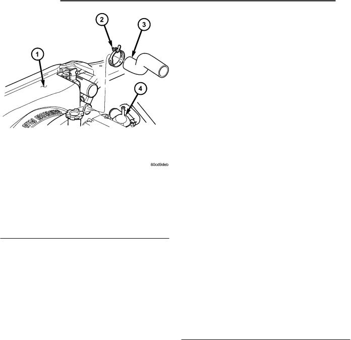
7 - 18 ENGINE
COOLING FAN (Continued)
Fig. 1 COOLING FAN SUPPORT
1 - IDLER PULLEY
2 - COOLING FAN SUPPORT
3 - RETAINING BOLTS
4 - ENGINE LIFT HOOK
(1)Remove fan blade assembly from fan drive viscous clutch (four bolts).
(2)Lay fan on a flat surface with leading edge facing down. With tip of blade touching flat surface, replace fan if clearance between opposite blade and surface is greater than 2.0 mm (.090 inch). Rocking motion of opposite blades should not exceed 2.0 mm (.090 inch). Test all blades in this manner.
(3)Inspect fan assembly for cracks, bends, loose rivets or broken welds. Replace fan if any damage is found.
KJ
COOLANT SYSTEM HOSES
REMOVAL
REMOVAL - UPPER RADIATOR HOSE
(1)Drain cooling system (Refer to 7 - COOLING/ ENGINE/COOLANT - STANDARD PROCEDURE).
(2)Disconnect upper radiator hose from thermostat housing (Fig. 2).
(3)Disconnect upper radiator hose from radiator and remove from vehicle (Fig. 2).
Fig. 2 UPPER RADIATOR HOSE
1 - FAN SHROUD
2 - HOSE CLAMP
3 - UPPER RADIATOR HOSE
4 - THERMOSTAT HOUSING
INSTALLATION
INSTALLATION - COOLING FAN
(1) (Refer to 7 - COOLING/ENGINE/FAN DRIVE VISCOUS CLUTCH - INSTALLATION)
INSTALLATION - COOLING FAN SUPPORT
(1)Install cooling fan support to engine block (Fig. 1). Torque bolts to 47.1N´m.
(2)Install fan drive viscous clutch and fan assembly (Refer to 7 - COOLING/ENGINE/FAN DRIVE VISCOUS CLUTCH - INSTALLATION).
(3)Connect negative battery cable.
REMOVAL - HEATER CORE HOSES
(1)Drain cooling system (Refer to 7 - COOLING/ ENGINE/COOLANT - STANDARD PROCEDURE).
(2)Remove engine cover from engine (Refer to 9 - ENGINE COVER - REMOVAL).
(3)Disconnect heater core supply line at heater core and viscous heater (Fig. 3). Remove hose from vehicle.
(4)Disconnect heater core return line from heater core and EGR cooler (Fig. 3). Remove hose from vehicle.

KJ
COOLANT SYSTEM HOSES (Continued)
Fig. 3 HEATER CORE COOLANT HOSES
1 - HEATER CORE TO VISCOUS HEATER HOSE
2 - MOUNTING STUD
3 - HOSE CLAMP
4 - HOSE CLAMP
5 - HEATER CORE TO EGR COOLER HOSE
INSTALLATION
INSTALLATION - UPPER RADIATOR HOSE
(1)Install upper radiator hose on radiator and thermostat housing (Fig. 2).
(2)Reposition hose clamps in proper position.
(3)Refill cooling system to proper level (Refer to 7
-COOLING/ENGINE/COOLANT - STANDARD PROCEDURE).
INSTALLATION ± HEATER CORE HOSES
(1)Connect heater core supply hose to heater core and viscous heater. Position hose clamps into proper position.
(2)Connect heater core return hose to heater core and EGR cooler. Position hose clamps into proper position.
(3)Install engine cover to engine (Refer to 9 - ENGINE COVER - INSTALLATION).
(4)Refill cooling system to proper level (Refer to 7
-COOLING/ENGINE/COOLANT - STANDARD PROCEDURE).
ENGINE 7 - 19
ENGINE COOLANT TEMP SENSOR
DESCRIPTION
The engine coolant temperature sensor threads into a coolant passage in the cylinder head (Fig. 4). New sensors have sealant applied to the threads.
Fig. 4 CYLINDER HEAD ASSEMBLY
1 - CYLINDER HEAD BOLT
2 - GLOW PLUG
3 - COOLANT TEMPERATURE SENSOR
4 - CYLINDER HEAD ALIGNMENT DOWEL
5 - GLOW PLUG HARNESS
6 - CYLINDER LINER
7 - CYLINDER BLOCK
8 - CYLINDER HEAD GASKET
9 - CYLINDER HEAD
10 - ROCKER ARM ASSEMBLIES
OPERATION
The coolant temperature (ECT) sensor is a negative temperature coefficient (NTC) thermistor (resistance varies inversley with temperature). This means at cold tempertures its resistance is high so the voltage signal will be high. As coolant temperture increases, resistance decreases and the signal voltage will be low. This allows the sensor to provide an analog voltage signal to the ECM.
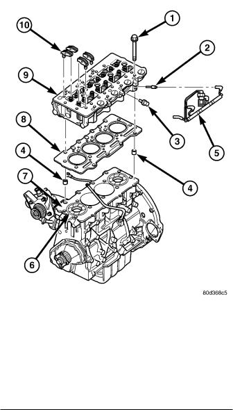
7 - 20 ENGINE |
|
KJ |
|
ENGINE COOLANT TEMP SENSOR (Continued)
REMOVAL
WARNING: DO NOT REMOVE OR LOOSEN THE COOLANT PRESSURE/VENT CAP, CYLINDER BLOCK DRAIN PLUGS, OR THE DRAINCOCK WHEN THE SYSTEM IS HOT AND UNDER PRESSURE BECAUSE SERIOUS BURNS FROM THE COOLANT CAN OCCUR.
(1)Disconnect negative battery cable.
(2)Drain the cooling system. (Refer to 7 - COOLING/ENGINE/COOLANT - STANDARD PROCEDURE)
(3)Disconnect coolant temperature sensor electrical connector (Fig. 5).
(4)Remove coolant temperature sensor from cylinder head (Fig. 5).
Fig. 5 CYLINDER HEAD ASSEMBLY
1 - CYLINDER HEAD BOLT
2 - GLOW PLUG
3 - COOLANT TEMPERATURE SENSOR
4 - CYLINDER HEAD ALIGNMENT DOWEL
5 - GLOW PLUG HARNESS
6 - CYLINDER LINER
7 - CYLINDER BLOCK
8 - CYLINDER HEAD GASKET
9 - CYLINDER HEAD
10 - ROCKER ARM ASSEMBLIES
INSTALLATION
(1)Install coolant temperature sensor in cylinder head (Fig. 5).
(2)Connect coolant temperature sensor electrical connector (Fig. 5).
(3)Refill cooling system. (Refer to 7 - COOLING/ ENGINE/COOLANT - STANDARD PROCEDURE)
(4)Connect negative battery cable.
ENGINE COOLANT
THERMOSTAT
DESCRIPTION
A pellet-type thermostat controls the operating temperature of the engine by controlling the amount of coolant flow to the radiator (Fig. 6).
OPERATION
The thermostat starts to open at 80°C (176°F). Above this temperature, coolant is allowed to flow to the radiator. This provides quicker engine warmup and overall temperature control.
The same thermostat is used for winter and summer seasons. An engine should not be operated without a thermostat, except for servicing or testing. Operating without a thermostat causes other problems. These are: longer engine warmup time, unreliable warmup performance, increased exhaust emissions and crankcase condensation. This condensation can result in sludge formation.
REMOVAL
NOTE: The thermostat is not serviced separately. The thermostat and housing must be replaced as an assembly.
(1)Disconnect negative battery cable.
(2)Remove engine cover (Refer to 9 - ENGINE COVER - REMOVAL).
(3)Partially drain cooling system (Refer to 7 - COOLING/ENGINE/COOLANT - STANDARD PROCEDURE).
(4)Disconnect upper radiator hose and bypass hoses at thermostat housing.
(5)Remove thermostat housing retaining bolts, support bracket (2.8L) and housing from cylinder head, discard gasket (Fig. 7).
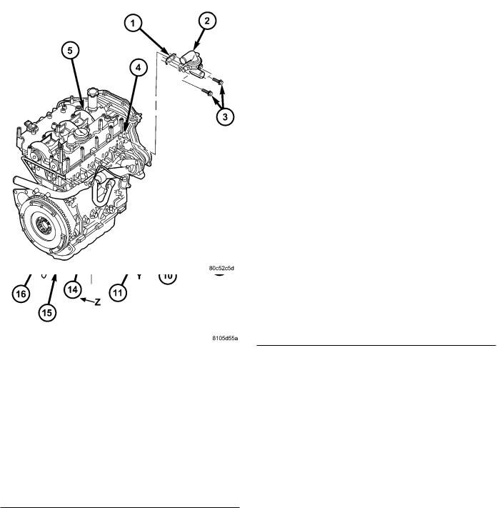
KJ |
|
ENGINE 7 - 21 |
|
ENGINE COOLANT THERMOSTAT (Continued)
Fig. 6 THERMOSTAT HOUSING
1 - THERMOSTAT HOUSING GASKET
2 - THERMOSTAT HOUSING
3 - TURBOCHARGER OIL SUPPLY LINE BANJO BOLT
4 - THERMOSTAT HOUSING RETAINING BOLTS
5 - BRASS WASHER
6 - EXHAUST MANIFOLD GASKET
7 - EXHAUST MANIFOLD
8 - EXHAUST MANIFOLD HEATSHIELD
9 - EXHAUST MANIFOLD HEATSHIELD RETAINING BOLTS
10 - OIL RETURN HOSE
11 - HOSE CLAMPS
12 - EXHAUST MANIFOLD RETAINING NUTS
13 - TURBOCHARGER DOWNPIPE STUDS
14 - TURBOCHARGER DOWN PIPE GASKET
15 - TURBOCHARGER DOWNPIPE
16 - TURBOCHARGER DOWNPIPE RETAINING NUT
INSTALLATION
(1)Clean old gasket material from cylinder head and thermostat housing.
(2)Install thermostat housing with gasket and support bracket (2.8L) to cylinder head (Fig. 7). Torque bolts to 27.5N´m.
(3)Connect coolant bypass hose and upper radiator hose to thermostat housing.
(4)Refill cooling system (Refer to 7 - COOLING/ ENGINE/COOLANT - STANDARD PROCEDURE).
Fig. 7 THERMOSTAT HOUSING ASSEMBLY
1 - THERMOSTAT HOUSING GASKET
2 - THERMOSTAT HOUSING
3 - RETAINING BOLTS
4 - CYLINDER HEAD
5 - CYLINDER HEAD COVER/INTAKE MANIFOLD
(5)Install engine cover (Refer to 9 - ENGINE COVER - INSTALLATION).
(6)Connect negative battery cable.
FAN DRIVE VISCOUS CLUTCH
DESCRIPTION
CAUTION: If the viscous fan drive is replaced because of mechanical damage, the cooling fan blades should also be inspected. Inspect for fatigue cracks, loose blades, or loose rivets that could have resulted from excessive vibration. Replace fan blade assembly if any of these conditions are found. Also inspect water pump bearing and shaft assembly for any related damage due to a viscous fan drive malfunction.
The thermal viscous fan drive (Fig. 8) is a silicone- fluid-filled coupling used to connect the fan blades to the fan support bracket assembly. The coupling allows the fan to be driven in a normal manner. This is done at low engine speeds while limiting the top speed of the fan to a predetermined maximum level at higher engine speeds.
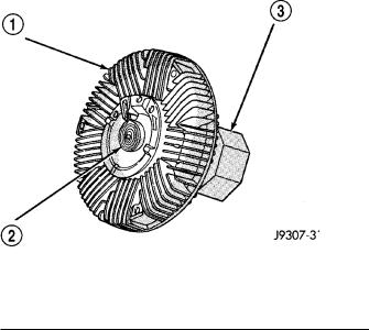
7 - 22 ENGINE |
|
KJ |
|
FAN DRIVE VISCOUS CLUTCH (Continued)
On the 2.5L Diesel engine, a viscous fan is standard.
Fig. 8 Viscous Fan Drive - Typical
1 - VISCOUS FAN DRIVE
2 - THERMOSTATIC SPRING
3 - MOUNTING NUT TO WATER PUMP HUB
OPERATION
A thermostatic bimetallic spring coil is located on the front face of the viscous fan drive unit. This spring coil reacts to the temperature of the radiator discharge air. It engages the viscous fan drive for higher fan speed if the air temperature from the radiator rises above a certain point. Until additional engine cooling is necessary, the fan will remain at a reduced rpm regardless of engine speed. Normally less than three hundred (300) rpm.
Only when sufficient heat is present, will the viscous fan drive engage. This is when the air flowing through the radiator core causes a reaction to the bimetallic coil. It then increases fan speed to provide the necessary additional engine cooling.
Once the engine has cooled, the radiator discharge temperature will drop. The bimetallic coil again reacts and the fan speed is reduced to the previous disengaged speed.
DIAGNOSIS AND TESTING - FAN DRIVE VISCOUS CLUTCH
If the fan assembly free-wheels without drag (the fan blades will revolve more than five turns when spun by hand), replace the fan drive. This spin test must be performed when the engine is cool.
For the following test, the cooling system must be in good condition. It also will ensure against excessively high coolant temperature.
WARNING: BE SURE THAT THERE IS ADEQUATE FAN BLADE CLEARANCE BEFORE DRILLING.
(1)Drill a 3.18-mm (1/8-in) diameter hole in the top center of the fan shroud.
(2)Obtain a dial thermometer with an 8 inch stem (or equivalent). It should have a range of -18° to 105°C (0° to 220° F). Insert thermometer through the hole in the shroud. Be sure that there is adequate clearance from the fan blades.
(3)Connect a tachometer and an engine ignition timing light (timing light is to be used as a strobe light).
(4)Block the air flow through the radiator. Secure a sheet of plastic in front of the radiator (or air conditioner condenser). Use tape at the top to secure the plastic and be sure that the air flow is blocked.
(5)Be sure that the air conditioner (if equipped) is turned off.
WARNING: USE EXTREME CAUTION WHEN THE ENGINE IS OPERATING. DO NOT STAND IN A DIRECT LINE WITH THE FAN. DO NOT PUT YOUR HANDS NEAR THE PULLEYS, BELTS OR FAN. DO NOT WEAR LOOSE CLOTHING.
(6)Start the engine and operate at 2400 rpm. Within ten minutes the air temperature (indicated on the dial thermometer) should be up to 93° C (200° F). Fan drive engagement should have started to occur at between 91° to 96° C (195° to 205° F). Engagement is distinguishable by a definite increase in fan flow noise (roaring). The timing light also will indicate an increase in the speed of the fan.
(7)When the air temperature reaches 93° C (200° F), remove the plastic sheet. Fan drive disengagement should have started to occur at between 62° to 85° C (145° to 185° F). A definite decrease of fan flow noise (roaring) should be noticed. If not, replace the defective viscous fan drive unit.
REMOVAL
(1) Disconnect negative battery cable.
NOTE: The thermal viscous fan drive/fan blade assembly is attached (threaded) to fan support.
(2)Remove fan blade/viscous fan drive assembly from water pump using special tool 6958 spanner wrench, by turning mounting nut counterclockwise as viewed from front (Fig. 9) (Fig. 10). Threads on viscous fan drive are RIGHT HAND.
(3)Do not attempt to remove fan/fan drive viscous clutch assembly from vehicle at this time.
(4)Do not unbolt fan blade assembly from fan drive viscous clutch at this time.
(5)Remove fan shroud to radiator bolts.
(6)Remove fan shroud and fan blade/fan drive viscous clutch assembly as a complete unit from vehicle.
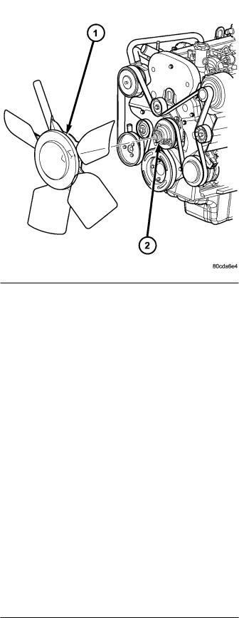
KJ |
|
ENGINE 7 - 23 |
|
FAN DRIVE VISCOUS CLUTCH (Continued)
Fig. 9 FAN DRIVE VISCOUS CLUTCH - TYPICAL
1 - SPECIAL TOOL 6958 SPANNER WRENCH
2 - FAN
Fig. 10 COOLING FAN AND VISCOUS CLUTCH
1 - COOLING FAN AND FAN DRIVE VISCOUS CLUTCH ASSEMBLY
2 - FAN SUPPORT
(7)After removing fan blade/fan drive viscous clutch assembly, do not place viscous clutch in horizontal position. If stored horizontally, silicone fluid in the fan drive viscous clutch could drain into its bearing assembly and contaminate lubricant.
(8)Remove four bolts securing fan blade assembly to fan drive viscous clutch.
INSTALLATION
(1) Assemble fan blade to viscous fan drive. Tighten mounting bolts to 27 N´m (20 ft. lbs.) torque.
NOTE: The viscous fan and fan shroud must be installed as an assembly.
(2)Gently lay fan and viscous drive into fan shroud.
(3)Install the fan shroud to radiator mounting bolt. Torque bolts to 5.5N´m.
(4)Thread the fan and viscous drive onto the fan support and tighten nut using special tool 6958 spanner wrench.
(5)Connect negative battery cable.
RADIATOR
REMOVAL
(1)Disconnect negative battery cable.
(2)Drain cooling system (Refer to 7 - COOLING/ ENGINE - STANDARD PROCEDURE).
(3)Remove engine oil fill cap.
(4)Remove engine cover (Refer to 9 - ENGINE COVER - REMOVAL).
(5)Remove air filter assembly from the engine bay.
(6)Recover and evacuate the refrigerant system (Refer to 24 - HEATING & AIR CONDITIONING/ PLUMBING - STANDARD PROCEDURE) and (Refer to 24 - HEATING & AIR CONDITIONING/PLUMBING - STANDARD PROCEDURE).
(7)Disconnect high side refrigerant line from the upper radiator support bracket.
(8)Remove upper radiator support bracket retaining bolts and remove the support bracket.
(9)Remove high side refrigerant line retaining nut and remove the line from the condenser assembly. Position the line out of the way.
(10)Unbolt cooling fan from cooling fan support.
(11)Remove fan shroud retaining bolts and remove the fan and shroud as an assembly.
(12)Disconnect charge air cooler hoses from the charge air cooler.
(13)Disconnect engine coolant hoses from the radi-
ator.
(14)Disconnect coolant reservoir hose from the radiator.
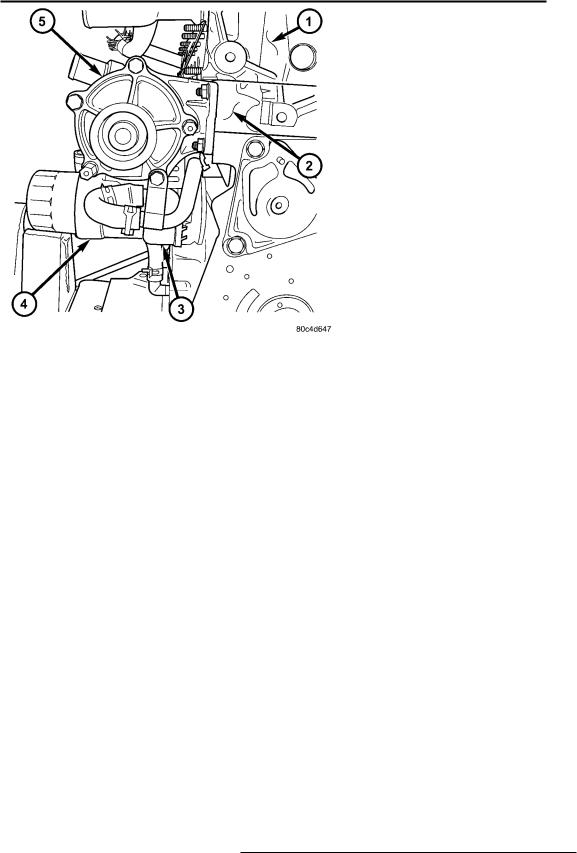
7 - 24 ENGINE
RADIATOR (Continued)
(15)Remove low side refrigerant line retaining nut and remove the line from the condenser assembly. Position the line out of the way.
(16)Remove condenser assembly retaining bolts and remove the condenser from the vehicle.
(17)Remove power steering cooler retaining bolts and unclip the air deflectors from both sides of the radiator (cooling module) assembly.
(18)Lift cooling module assembly out of the engine
bay.
(19)Remove radiator retaining bolts and remove the cooling system module from vehicle.
(20)Separate charge air cooler from radiator.
INSTALLATION
(1)Install radiator on the charge air cooler and install retaining bolts.
(2)Install radiator (cooling module) assembly in the engine bay.
(3)Install power steering cooler retaining bolts and clip the air deflectors on both sides of the radiator (cooling module) assembly.
(4)Install condenser assembly and retaining bolts.
(5)Install low side refrigerant line and retaining
nut.
(6)Connect coolant reservoir hose on the radiator.
(7)Connect engine coolant hoses on the radiator.
(8)Connect charge air cooler hoses on the charge air cooler.
(9)Install fan and fan shroud assembly and retaining bolts.
(10)Install cooling fan assembly to cooling fan support.
(11)Install high side refrigerant line and retaining
nut.
(12)Install upper radiator support bracket and retaining bolts.
(13)Connect high side refrigerant line on the upper radiator support bracket.
(14)Evacuate and re-charge the refrigerant system (Refer to 24 - HEATING & AIR CONDITIONING/PLUMBING - STANDARD PROCEDURE).
(15)Install air filter assembly in the engine bay.
(16)Install engine cover (Refer to 9 - ENGINE COVER - INSTALLATION).
(17)refill cooling system (Refer to 7 - COOLING/ ENGINE - STANDARD PROCEDURE).
(18)Connect negative battery cable.
KJ
WATER PUMP
DESCRIPTION
The water pump on the 2.5L/2.8L CRD diesel has a die cast aluminum housing. It bolts to a aluminum housing which attaches to the engine block.
OPERATION
The water pump is used to circulate coolant through the cooling system. The coolant is pumped through the engine block, cylinder head, heater core, EGR cooler, viscous heater, and radiator.
REMOVAL - WATER PUMP
(1)Disconnect negative battery cable.
(2)Drain cooling system (Refer to 7 - COOLING/ ENGINE/COOLANT - STANDARD PROCEDURE).
(3)Remove timing belt inner and outer covers (Refer to 9 - ENGINE/VALVE TIMING/TIMING BELT / CHAIN COVER(S) - REMOVAL).
(4)Remove water pump retaining bolts and pump (Fig. 11).
Fig. 11 WATER PUMP LOCATION
1 - CYLINDER HEAD
2 - ENGINE BLOCK
3 - OIL COOLER
4 - OIL FILTER HOUSING
5 - WATER PUMP
CLEANING
Clean gasket mating surfaces as necessary.
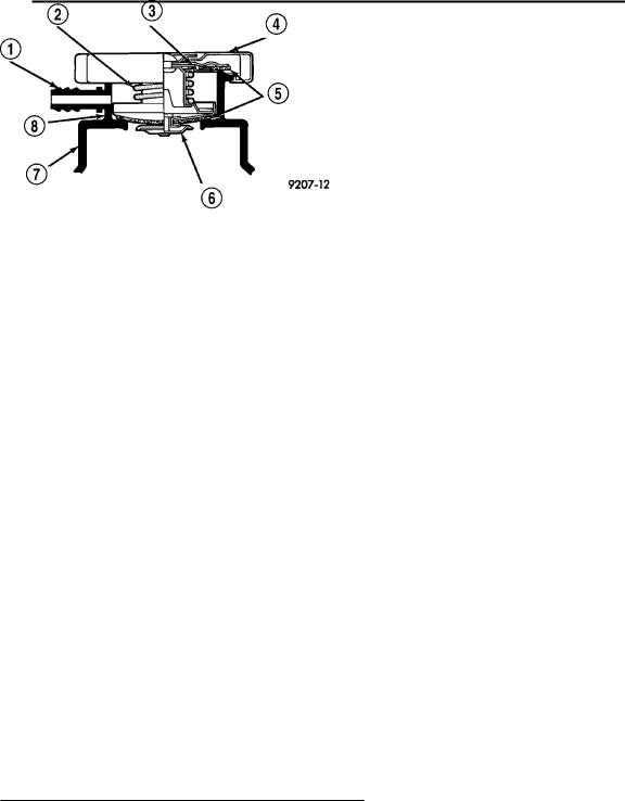
KJ
WATER PUMP (Continued)
INSTALLATION
(1)Clean mating surfaces of water pump housing and engine block as necessary.
(2)Place new o-ring in groove in water pump housing. Install water pump and retaining bolts. Torque bolts to 24.4N´m.
(3)Install both inner and outer timing belt covers (Refer to 9 - ENGINE/VALVE TIMING/TIMING BELT / CHAIN COVER(S) - INSTALLATION).
(4)Refill cooling system (Refer to 7 - COOLING/ ENGINE/COOLANT - STANDARD PROCEDURE).
(5)Connect negative battery cable.
ENGINE 7 - 25
through a connecting hose. If valve is stuck shut, or the coolant recovery hose is pinched, the radiator hoses will be collapsed on cool down. Clean the vent valve (Fig. 12) and inspect coolant recovery hose routing, to ensure proper sealing when boiling point is reached.
The gasket in the cap seals the filler neck, so that vacuum can be maintained, allowing coolant to be drawn back into the radiator from the reserve tank.
If the gasket is dirty or damaged, a vacuum may not be achieved, resulting is loss of coolant and eventual overheating due to low coolant level in radiator and engine.
RADIATOR PRESSURE CAP
DESCRIPTION
The cooling system pressure cap is located on the coolant recovery pressure container. The cap construction includes; stainless steel swivel top, rubber seals, and retainer, main spring, and a spring loaded valve (Fig. 12).
Fig. 12 Cooling System Pressure Cap Filler Neck
1 - OVERFLOW NIPPLE
2 - MAIN SPRING
3 - GASKET RETAINER
4 - STAINLESS-STEEL SWIVEL TOP
5 - RUBBER SEALS
6 - VENT VALVE
7 - PRESSURE BOTTLE
8 - FILLER NECK
OPERATION
The cooling system is equipped with a pressure cap that releases excessive pressure; maintaining a range of 97-124 kPa (14-18 psi).
The cooling system will operate at higher than atmospheric pressure. The higher pressure raises the coolant boiling point thus, allowing increased radiator cooling capacity.
There is also a vent valve in the center of the cap. This valve also opens when coolant is cooling and contracting, allowing the coolant to return to cooling system from coolant reserve system tank by vacuum
DIAGNOSIS AND TESTING
DIAGNOSIS AND TESTING - COOLING SYSTEM PRESSURE CAP
Dip the pressure cap in water. Clean any deposits off the vent valve or its seat and apply cap to end of the Pressure Cap Test Adaptor that is included with the Cooling System Tester 7700. Working the plunger, bring the pressure to 104 kPa (15 psi) on the gauge. If the pressure cap fails to hold pressure of at least 97 kPa (14 psi), replace the pressure cap.
CAUTION: The Cooling System Tester Tool is very sensitive to small air leaks that will not cause cooling system problems. A pressure cap that does not have a history of coolant loss should not be replaced just because it leaks slowly when tested with this tool. Add water to the tool. Turn tool upside down and recheck pressure cap to confirm that cap is bad.
If the pressure cap tests properly while positioned on Cooling System Tester (Fig. 13), but will not hold pressure or vacuum when positioned on the filler neck. Inspect the filler neck and cap top gasket for irregularities that may prevent the cap from sealing properly.
DIAGNOSIS AND TESTING - PRESSURE RELIEF TEST
The pressure cap upper gasket (seal) pressure relief can be checked by removing the overflow hose at the radiator filler neck nipple (Fig. 14). Attach the Radiator Pressure Tool to the filler neck nipple and pump air into the radiator. Pressure cap upper gasket should relieve at 69-124 kPa (10-18 psi) and hold pressure at 55 kPa (8 psi) minimum.
Loading...